DI-BOX FLOWBOX User manual

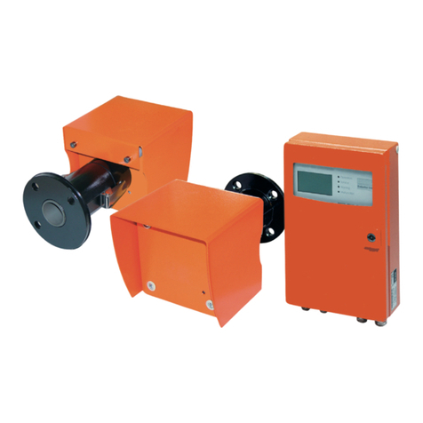
Flow meter:
ULTRASONICFLOW METER
FLOWBOX
Rising element:
PALMER-BOWLUSFLUME
ZPB160
User’smanual
Wroc aw2020
FLOWBOX
TRANSMITTER

www.di-box.com.pl – User’s manual
------------------------------------------------------------------------------------------------------------------------------------------------------------------------
Copyright © DI-BOX2020, www.di-box.com.pl,info@di-box.com.pl
1
Thankyoufor choosing productofourfirm.
TheDI-BOXcompanyguarantees thebig quality
ofthepurchased deviceand its proper operation.
The guarantee period for thepurchased apparatus covers: 18months.
Thepresent deviceismanufacturedinconformitywiththestandards
requiredfordigitaltools Bclass.
Thismanual wasissuedonlyinorderforinformation purposes.All information
includedcanbechanged.The DI-BOX doesnot bearthe responsibility forany direct
and indirectdefects arisen as aresult of using this manual.
HEALTHANDSAFETY.The assembly, starting,service, maintenanceand
repairs canbemadeexclusively bythe qualifiedpersonnel inaccordancewith the
obligatorysafetyprinciples.
Thedeviceissafeand works properly,ifitisproperlytransported, stored,
installed, startedup, servicedand maintained. Theproductshouldbeused
inaccordancewiththemanual.
HEALTHANDSAFETY. CAUTION:Theimproperservicemaycause
gettinghurtorseriousdevicedamage.
Zak adAparaturyKontrolno-Pomiaroweji Automatyki Przemys owej
ul.Szczeci ska11a 54-517 Wrocław
tel.071 353 86 55, 602 4844 77 fax. 071 353 86 54
info@di-box.com.pl www.di-box.com.pl

www.di-box.com.pl - Instrukcjaobs ugi
------------------------------------------------------------------------------------------------------------------------------------------------------------------------
Copyright © DI-BOX2020, www.di-box.com.pl,info@di-box.com.pl
2
TABLEOFCONTENTS
1.INITIAL INFORMATION..............................................................................
3
2.TECHNICAL DATA...................................................................................... 3
2.1.Flowmeasuring transmitter M1600.................................................. 3
2.2.Ultrasound level sensor SPA380-4.................................................... 4
2.3.Palmer Bowlus ZPBflume ................................................................
5
3.INSTALLATIONOFMEASURINGSET ........................................................... 7
3.1.Assembly recommendations ............................................................. 7
3.2.Connecting the wires to the transmitter M1600 ................................. 9
3.3.Scheme of electric connections of the transmitter M1600................... 10
4.DEVICESERVICE......................................................................................11
4.1.Displayof device.............................................................................11
4.2.Devicecalibration ............................................................................12
4.3.Measuring scopeand input electric current set ...................................
14
5.MODBUSINTERFACE................................................................................15
5.1.Technicaldata................................................................................15
5.2.Installation and launchoftheMODBUSinterface...............................
16
5.3.Description of registers of thetransmitter M1600..............................17
6.MAINTENANCERECOMMENDATIONS.........................................................18
6.1.Palmer-Bowlus ZPBflume ultrasonic sensor SPA380-4........................18

www.di-box.com.pl – User’s manual
------------------------------------------------------------------------------------------------------------------------------------------------------------------------
Copyright © DI-BOX2020, www.di-box.com.pl,info@di-box.com.pl
3
1. INITIALINFORMATION
The measuringset servesasnot foamedliquidintensitymeasureflowin the
gravitationconditionsandtotalamount ofsewageflowingthroughthemeasuring
channel.
Inthe scopeofthisapplication,the FLOWBOXflowmeterdeterminesthe temporary
flowon the basisof liquidaccumulationinthePalmer-Bowlusflume ZPB160,in
accordancewith theguidelinesandrecommendationsofthe ISO4359:1983
standard.
Thebasic conditiontoapplythemethodistoprovidefree,
undisturbedinflow and outflow of liquidfromthemeasuringflume.
Measuring set consists of:
→Flowmeasuring transmitter M1600,
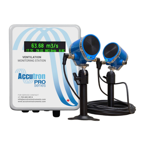
→Ultrasonic level sensor SPA380-4,
→Palmer-Bowlus ZPB160 flume.
2. TECHNICALDATA
2.1.Flowmeasuring transmitter M1600
→MEASURINGSCOPES:
Intensity flowmeasurement: for ZPB160
-in the entities m3/h: 40 m3/h

www.di-box.com.pl - Instrukcjaobs ugi
------------------------------------------------------------------------------------------------------------------------------------------------------------------------
Copyright © DI-BOX2020, www.di-box.com.pl,info@di-box.com.pl
4
-in the entities m3(summary): 0...1.000000
→PROGRAMMING: local, for Palmer-Bowlus ZPB160
→OUTPUTSSIGNALS: (electroplating separation in/out)
Current output: 0/4...20mA, load 500 Ωmax.
Impulseoutput: every0,1m3,type:opencolector
Digitaloutput: RS485/MODBUSRTU
→OTHERDATA:
Power supply: ~230V,50Hz
Power consumption: ≤10 VA
Mass: ~1,5kg
Material: ABS
Protection class: IP65
Worktemperaturescope(without
protective case): -10 do55
o
C
2.2.Ultrasoniclevel sensor SPA 380-4
SPA380 isthe ultrasonicinlet ofdistanceforstandard current signalintendedfor
measuring the liquid level changes.
The basicusageissituatedatmeasuringlevelinindustrialandmunicipalsewage
treatment plants,batchandreserve tanks,wells,sewagewet wells,measuring
instruments in open channels,etc.

www.di-box.com.pl – User’s manual
------------------------------------------------------------------------------------------------------------------------------------------------------------------------
Copyright © DI-BOX2020, www.di-box.com.pl,info@di-box.com.pl
5
The deviceismadein the formof measuringprobehavingthe microprocessor
measuring instrument and ultrasound sensor.
The casingof the probeismadeof PVCwhatassuresthe widescopeof usagesin
different environmentconditions.
The membrane of ultrasoundsensorissituatedinsidethe casingandcommunicates
with frontalsurfaceof the probebythe acousticcouplerwhatprotectsit againstthe
influenceof environment conditions (humidity, caustic fumes,etc.)
The probehasthe function of automaticcleaningoffrontalsurfaceof radiatorwith
gathering sediments bythe instantincreaseof the ultrasound wave emitted power.
SPECIFICATION
Technicalparameters:
→Accuracy: 0.10%of the scopein the laboratoryconditions
0.25%of the scopein the field conditions
→Resolution: 0,7mm
→Measuring scope: 0,25…4,0m.
→Signalbeam curve: 5-7°with decreaseof the power of 3d
→Temperaturecompensation:automatic
Output:
→Analogue output:: 4…20mA or20…4mA
→Max.load:R=(Uzas.-6)24mA
Feeding: 18to 30VDC max.0.07A
Protectionclass: IP68
Threaddiameter: 2.0" NPT
2.3. Palmer-BowlusZPBflume
Palmer-Bowlusmeasuringflumeisone of the prefabricatedmeasuringflumes
intendedformeasuringthe flowin gravitation wires.Itisrecommendedto gravitation
channels with circular section andpipelines working without pressure.
The channel assuresexactrelation between the level of itsfillingandliquidflow
intensity in the channelor pipeline.

www.di-box.com.pl - Instrukcjaobs ugi
------------------------------------------------------------------------------------------------------------------------------------------------------------------------
Copyright © DI-BOX2020, www.di-box.com.pl,info@di-box.com.pl
6
Thebasic conditiontoapplythemethodistoprovidefree,
undisturbedinflow and outflow of liquidfromthemeasuringflume.
Typ
koryta
DN Q
m/h
B
L
Typ
koryta DN
Q
m/h
B
L
ZPB100
Ø110
12
155
800
ZPB400 Ø400
450
450
1500
ZPB160
Ø160
40
210
800
ZPB500 Ø500
730
550
1700
ZPB200
Ø200
70
250
1190
ZPB600 Ø630
980
685
2000
ZPB250
Ø250
130
305
1190
ZPB800 Ø800
1700
860
2600
ZPB300
Ø315
220
368
1400
ZPB1000
Ø1000
4380
1050
3500
Inordertoobtaintheproperflowintensity,theflume mustbe
installedhorizontallywithoutfall.

www.di-box.com.pl – User’s manual
------------------------------------------------------------------------------------------------------------------------------------------------------------------------
Copyright © DI-BOX2020, www.di-box.com.pl,info@di-box.com.pl
7
3. INSTALLATION OFMEASURING SET
3.1. Assemblyrecommendations
PALMER-BOWLUSFLUMEZPB
→Install the flume on thepipelinebymeansof insertingchannelin pipeline
goblet ortypicalhydraulicmuff inthe wayof assuringthe durability and
tightness of the connection,rememberingabout the properflume
orientation (the indicatorin the channel shows the flowdirection).
→Install theflumeinthehorizontalpositionwithout drops.
→Performsupportof the flumeassuring its immobilization
→Handle mustscrewedto the channel in the given placesbymeansof eight
M5 screws
INLETANDOUTLETCHANNELS
→Providefree, undisturbed inflowand outflowof liquid from the measuring
flume bymeans of ensuring long enoughstraight inlet and outlet channel
parts.
ULTRASONICLEVEL SENSOR SPA 380-4
→SPA380-4sensorshouldbeinstalledinthedurable andsafe wayin the
given measuringhandle. The handle screwedto the reducerbymeansof
2x4M5 shouldguaranteedsolidandsafe placement of the sensorduring
work.
→Put the measuring sensorin thehandle in accordancewith thedrawing.Use
the washers.Screwthe nuts 2,0".
→The wayof ultrasonic signalshould befree of any disturbances.
→The surfaceof the assembly should befree of vibrations.
→The surrounding temperatureshould bebetween -20˚C....+70˚C
→Thereshouldnot betheelectricpowercablesorelectricpowerconverters
nearby.

www.di-box.com.pl - Instrukcjaobs ugi
------------------------------------------------------------------------------------------------------------------------------------------------------------------------
Copyright © DI-BOX2020, www.di-box.com.pl,info@di-box.com.pl
8
Incaseof sensorinstallationoutsideyou shouldcoverit againstthe
sunbeams and environment conditions.
Thedeliveredsensor380-4SPA iscalibratedforthedetermined
typeofflumeand doesnotrequireanysettingsbytheuser.Thechangeof
factorysettings will causeerrorofmeasuringtransmitterM1600.
MEASURINGTRANSMITTERM1600
→Itis recommendedtousethe roofing ofthetransmitter protectingitagainst
directinfluenceof the atmosphericfactors (forinstance:rain, snow) or
installation in safetycase.
→HEALTHANDSAFETY.Inorderto assurethe safety of service(for
instance:duringthe startingup,maintenanceandcleaning)the transmitter
should bemounted in the easyavailable place.
→All connectionsofelectricwiresshouldbeplacedastopreventfrom their
mechanicaldamage.
→The installation of the devicemustmeetswith electromagnetic
compatibility rules.
→The influenceof the disturbancesof the otherdeviceson the flowmeter
work mustbestrictlyeliminated!

www.di-box.com.pl – User’s manual
------------------------------------------------------------------------------------------------------------------------------------------------------------------------
Copyright © DI-BOX2020, www.di-box.com.pl,info@di-box.com.pl
9
Rys.Dimensions of M1600transmitter and spanof holes for mounting bolts
NOTESREFERRINGTO SETFUNCTIONING:
Inorderto assurethe properfunctioningofthe measuringset, pleaseto workin
accordancewith the manual.
3.2.Connecting thewires to thetransmitter M1600
Inorderto connectthe signal, output andpowersupply wiresto the transmitterstrip
terminal in accordanceelectric scheme (chapter 3.3),you should:
→Unscrewtwoscrewsvisible on thefrontalboard,
→Insertsignal, power supply and output wires into the proper throttles,
→Connectthewiresto theterminalstripandimmobilizethem screwingthe
throttles to the end.
HEALTHAND SAFETY:All
electric connectionsshouldbemade
during switchedoff powersupplyof
themeasuring transmitterM1600.
Do not touchthe stripjointswhile making
the connectionof the wiresto theterminal
strips (usethe screwdriverswith the
isolations,hang the wires on isolation).
Unscrewand take off acover

www.di-box.com.pl - Instrukcjaobs ugi
------------------------------------------------------------------------------------------------------------------------------------------------------------------------
Copyright © DI-BOX2020, www.di-box.com.pl,info@di-box.com.pl
10
3.3.Scheme ofelectricconnections ofthetransmitterM1600
PLC connection to impulseoutput.
Resistor should limit acurrent to max 150mA.
For PLC R=~2-3kΩ.
Installation ofthe devicemustmeets the electromagnetic compatibility rules.
Theinfluenceofthedisturbancesoftheotherdevicesonthe
flowmeterworkmustbestrictly eliminated!
POWER
SUPPLY
-
+
230VAC
N L
Power supply
: 230VA
C,50Hz
CURRENT
OUTPUT
DIGITAL
OUTPUT
Rs485
A
B
COM
SPA-380 SENSOR
SIGNAL INPUT IMPULSE
OUTPUT
SPA-380
We
-
+
Ch V
Count V
I
-
I+
Kabelczujnika SPA
-
380 : LiYCY 2x0,35mm ekr.
BRĄZOWYBIAŁYCZARNY
Ch V
ImA
PLC TransmitterM1600
Impulse output
I+
I
-
24V
DI
0V
R

www.di-box.com.pl – User’s manual
------------------------------------------------------------------------------------------------------------------------------------------------------------------------
Copyright © DI-BOX2020, www.di-box.com.pl,info@di-box.com.pl
11
4. DEVICE SERVICE
The measuringsetwasconfiguredto measurementtheintensityandamount
of sewagesbyusingthe measuringchannel Plamer-BowlusZPB160andlevel sensor
SPA380-4.The characteristics of measuringchannel andpropermeasuringformula
wasimplementedtothe M1600transmittermemory.Theusershouldonly setthe
parameter h0in accordancewith the point. 4.2.
Inthe event of changethe sensorormeasuringflume the M1600transmitter should
beprogrammedinthecompanyDI-BOX.
4.1.Displayofdevice
The four-buttons keyboard and liquid-crystalunit areto communicatewith the user.
Afterconnectingthe measuringset in accordancewith the electricscheme (point.
3.2.),to the factorof the transmittertherewill beprojectedthefollowingissues:
indicationsof liquidflowintensityin m
3
/h, summaryamount flowingthroughthe
measuring flume and actualvalueof the liquid level in the flume.
By pressingthe button ∧or ∨you may switchamain displayforaninformation of
unit time duration and power stoppage.
Flow intensity
Summary liquidamount
Valueof theliquid levelin
theflume[cm]
V =21.4m3/h9.0
Q =20m3
V =21.4m3/h9.0
Q=20 m3

www.di-box.com.pl - Instrukcjaobs ugi
------------------------------------------------------------------------------------------------------------------------------------------------------------------------
Copyright © DI-BOX2020, www.di-box.com.pl,info@di-box.com.pl
12
Projecting the announcement:
→means incorrectconnection ofultrasonic sensor with aM1600transmitter.
Projecting the announcement:
→means exceeding aflume’s flowrange.
When the #or*characters appearin the display,it indicatesaconnection tothe
Modbus network:
#The M1600transmitter is connected to the Modbus network.
*The M1600 transmitterisconnectedto the Modbusnetwork,the M1600andMaster
areproperly configured.
** The M1600transmitterisconnectedto the Modbusnetwork, the M1600andthe
Masterarecorrectly configured.InquirywasreceivedfromMasterandresponse
was obtained from M1600 transmitter.
4.2.Devicecalibration
Afterproperinstallation of measuringset you shouldmake the measurement ofthe
settingof ultrasoundsensorSPA380-4with relation to the measuringfeet of ZPB160
flume and enter into the memoryof the M1600transmitter.
Timeduration
Number ofpower stoppage
V =! !! 20.0
Q =20m3
duration stopp
1:2511
SENSOR?h0.0
Q =20m3
V =21.4m3/h9.0
Q =20 m3**

www.di-box.com.pl – User’s manual
------------------------------------------------------------------------------------------------------------------------------------------------------------------------
Copyright © DI-BOX2020, www.di-box.com.pl,info@di-box.com.pl
13
Itis the mosteffectivewayto dothis:
→Plug the input partof measuring channel,
→Fill the inputpartwith waterasto overflowthe waterthroughthe
measuring feet and water level levels to the measuring feet,
→Checkthe value of the fillingindicatedbythetransmitterM1600on
the displayatfactorysettings:
Ifthe fillingvalue hon the displayis anotherthan"0" (on the drawing h=-0.1) in
theseconditions (the lackof flow) you should:
→Press the button CAL throughabout 20-30seconds until the announcement
displays:
Itmeansthatthe ultrasoundsensorSPA380-4front -inaccordancewith factorysettings
-is 52.4cmfrom the surfaceof ZPBflume’s measuring feet.
→Buttons ∨(or^dependson situation)decrease(orincrease)the value H0
with sizehdisplayedbythe transmitterM1600 (in the describedexample
the value hwas -0.1cmsoyou need to increasethis valueh0,sotheproper
value h0is 52.4+0.1=52.5cm)
→press button SAVE
Aftermakingtheseactivitiesthereshouldbedisplayedthe actualvalue, filling(level)
of the liquid.
Ifthereisnot possible to performthe above-mentionedprocedureforsome reasons,
applyingthe solution with lowerexactness -physically measurethe distancefront
sensorfrom measuringfeet. Inorderto changethesettingthe followingshouldbe
performed:
V =0.0m3/h-0.1
Q =20 m3
h0 =52.4cm?
ZERO LEVEL
V =0.0m3/h0.0
Q =20 m3

www.di-box.com.pl - Instrukcjaobs ugi
------------------------------------------------------------------------------------------------------------------------------------------------------------------------
Copyright © DI-BOX2020, www.di-box.com.pl,info@di-box.com.pl
14
→Press the button CAL throughabout 20-30seconds until the announcement
displays:
→Buttons ∨or^set the new,with referenceto factorysettings,proper
distance-forthe channel ZPB, inaccordancewith the belowmentioned
drawing:
h0
→After measuring and setting theproper distance h0 you should press button
SAVE,whatwill beconfirmed by OK.
4.3.Measuring scopeand inputelectriccurrentset
Wanting to read outor set the measuring scopeor outflowcurrent, one should:
→Press the button SAVE throughabout 5seconds until the announcement
displays:
h0 =56.3cm?
ZERO LEVEL
0.0-40.04mA
measuringscope

www.di-box.com.pl – User’s manual
------------------------------------------------------------------------------------------------------------------------------------------------------------------------
Copyright © DI-BOX2020, www.di-box.com.pl,info@di-box.com.pl
15
Itmeansthatthe flowintensity measuringscopewithin the scope 0-40m3/h for
the current scope 4-20mA wasmanufacturedset. Ifthereisanecessity to change
it, you should press button CAL and then choseone of the scopebybuttons ∨or ^.
0
-
1
0
m
3
/h
0
-
20mA
0
-
2
0
m
3
/h
0
-
20mA
0
-
3
0
m
3
/h
0
-
20mA
0
-
4
0
m
3
/h
0
-
20mA
0
-
1
0
m
3
/h
4
-
20mA
0
-
2
0
m
3
/h
4
-
20mA
0
-
3
0
m
3
/h
4
-
20mA
0
-
4
0
m
3
/h
4
-
20mA
You should press SAVE whatwill beconfirmed by OK.
5. MODBUS INTERFACE
MODBUSinterfaceallowsforthe connection of oneormoremeasuringtransmitters
to acommon transmissionline ofthe RS-485 standard with the useof Modicon-
MODBUSprotocol. MODBUSinterfaceis characterized bythe following capabilities:
→reading the current measurementresults,
→reading the previously entered parameters,
→writing newparameters,
→examining the devicestatus.
5.1.Technical data
1.Transmission line:in accordancewith specification of the (EIA)RS-485standard.
2.Communication protocol:in accordancewith specificationof the Modicon-MODBUS
standard.
3.Maximum line length:1200m.
4.Galvanic barrier:for eachtransmitter.
5.Maximum number of logicalunits:247.
6.Maximum number of physicalunits connected to the line withoutarepeater:32.
7.Maximum access time to asingle station:below300ms.
8.Format of transmission for asingle character (asynchronous transmission):
→rate:9600bauds,
→number of bits:8(RTU),
→number of stop bits:1,

www.di-box.com.pl - Instrukcjaobs ugi
------------------------------------------------------------------------------------------------------------------------------------------------------------------------
Copyright © DI-BOX2020, www.di-box.com.pl,info@di-box.com.pl
16
→error control:no parity control (NONE PARITY).
9.Resistanceto interference:in accordancewith specification of the (EIA)RS-485
standard.
5.2.Installationand launchoftheMODBUSinterface
Connectionoftransmitters:
Transmitters mustbeconnectedto the existingline in accordancewith the figure
presented below:
PLC Data+(A)
R
R
A
B
Data-(B)
Mxxxx
Rs485
COM
A
B
COM
Rs485
ConnectionofM1600 transmittertotheMODBUSnetwork
R=100 –150
1W, depending onthe wave impedanceof the used cable.
Resistors can’tbeused in the caseof shortconnections.
ConfigurationoftheM1600transmitter:
Eachtransmitteroperatingin the networkmustbeproperly configuredwith the use
of keyboard throughassignmentofaunique identification number.
Determinationof thenumberidentifyingtransmitterinthenetwork:
→press andholdSAVEkey forapprox.15s-afterthistime, the message
MODBUSNUMBER will appearinthe bottom partof thedisplayandthe
current devicenumber will bedisplayed in the upper part,
→exit from the procedureoccurs after pressing SAVE key again,
→in orderto changethe current devicenumber,press CAL key andthen use
arrowkeys to set the desired devicenumber,and press SAVE key,
→pressing CAL key again beforepressing SAVE key will result in cancelling
the carriedout settings andreturnto the displayof thecurrentdevice
number.
R

www.di-box.com.pl – User’s manual
------------------------------------------------------------------------------------------------------------------------------------------------------------------------
Copyright © DI-BOX2020, www.di-box.com.pl,info@di-box.com.pl
17
5.3.Descriptionofregistersofthetransmitter M1600
Readingof the measurement resultsandsettingoftransmitterparameters occurs
through16-bit registers available viastandard functions of the MODBUSprotocol.
The followingreadingandwritingregisters aredistinguished FOR MEASURING
TRANSMITTERS:
→read with the useof function3(Read Holding Registers),
→written with the useof function 6(Write single register)
→address range0-65535
Types of variables:
UNSIGNED -16-bit unsigned integer,represented byone register.
FLOAT -32-bit floatingpoint value accordingto the IEEEstandard,representedby
tworegisters (32bits).
LONGINTEGER –32-bit totalvalue accordingto the IEEE standard,representedby
tworegisters (32bits).
ReadHolding Registers
1.Address:0,Format:FLOAT
LEVELin [m]-for the flowtransmitter,
2.Address:0,Format:FLOAT
FLOW in [m³/h]-for the flowtransmitter,
3.Address:0,Format:FLOAT
SUMMARYin [m³]-for the flowtransmitter,
4.Address:0,Format:FLOAT
ZEROLEVEL[m]-for the flowtransmitter,
Handling oferrors
Inthe Exception Response, the devicereturns error codes:
1–illegalfunction,
2–illegaladdress of registers,
3–illegalvalue of registers.
Handling oferrorsintheM1600transmitter
The following messages areshownon the transmitter display:
#-transmitters is connected to theModbus network,

www.di-box.com.pl - Instrukcjaobs ugi
------------------------------------------------------------------------------------------------------------------------------------------------------------------------
Copyright © DI-BOX2020, www.di-box.com.pl,info@di-box.com.pl
18
*-transmitterisconnectedto the Modbusnetwork, transmitterandMasterare
correctly configured,
*1 -illegalfunction,
*2 -illegaladdress of registers,
*3 -illegalvalue of registers,
*4 -CRCchecksum error.
6. MAINTENANCE RECOMMENDATIONS
5.1. Palmer BowlusZPB flume and ultrasonicsensor SPA 380-4
Checkthe permeability andclearness of the liquidpilingupelements(measuring
flume)dependingon needs.The maintenanceof the sensorSPA380-4refers to the
occasionalcheckof sensorsurfaceclearness andpossible wipingthe sensorfrontal
surfacewith the soft cloth.
This manual suits for next models
1
Table of contents
