KMB SMY 133 User manual

Contents
1 General Description 1
1.1 Version 2.0 improvements . . . . . . . . . . . . . . . . . . . . . . . . . . . . . . . . . . . . . . . . 1
1.2 Characteristic features . . . . . . . . . . . . . . . . . . . . . . . . . . . . . . . . . . . . . . . . . . 1
1.3 Typesandaccessories .......................................... 3
2 Operating the Meter 5
2.1 Safety requirements when using SMY 133 . . . . . . . . . . . . . . . . . . . . . . . . . . . . . . . 5
2.2 Installation of the instrument . . . . . . . . . . . . . . . . . . . . . . . . . . . . . . . . . . . . . . 5
2.2.1 Supplyvoltage .......................................... 6
2.2.2 Measuredvoltage......................................... 6
2.2.3 Measured currents . . . . . . . . . . . . . . . . . . . . . . . . . . . . . . . . . . . . . . . . 6
2.2.4 Communication peripherals . . . . . . . . . . . . . . . . . . . . . . . . . . . . . . . . . . . 7
2.2.5 Outputs and inputs . . . . . . . . . . . . . . . . . . . . . . . . . . . . . . . . . . . . . . . 10
2.3 Lock/unlock the instrument . . . . . . . . . . . . . . . . . . . . . . . . . . . . . . . . . . . . . . . 11
2.3.1 Locking the instrument . . . . . . . . . . . . . . . . . . . . . . . . . . . . . . . . . . . . . 11
2.3.2 Unlocking the instrument . . . . . . . . . . . . . . . . . . . . . . . . . . . . . . . . . . . . 11
2.4 Basic instrument setup (on screen) . . . . . . . . . . . . . . . . . . . . . . . . . . . . . . . . . . . 12
2.4.1 Installation type and options . . . . . . . . . . . . . . . . . . . . . . . . . . . . . . . . . . 12
2.4.2 Communication options . . . . . . . . . . . . . . . . . . . . . . . . . . . . . . . . . . . . . 13
2.4.3 Time and date options . . . . . . . . . . . . . . . . . . . . . . . . . . . . . . . . . . . . . . 13
2.5 Detailed configuration of SMY 133 on a PC . . . . . . . . . . . . . . . . . . . . . . . . . . . . . . 14
2.5.1 Installation (fig.16) . . . . . . . . . . . . . . . . . . . . . . . . . . . . . . . . . . . . . . . . 16
2.5.2 Date and time (fig. 17) . . . . . . . . . . . . . . . . . . . . . . . . . . . . . . . . . . . . . 18
2.5.3 Aggregation (averaging, fig. 18) . . . . . . . . . . . . . . . . . . . . . . . . . . . . . . . . . 19
2.5.4 Communication (fig. 19) . . . . . . . . . . . . . . . . . . . . . . . . . . . . . . . . . . . . . 19
2.5.5 Inputs & Outputs (fig. 20) . . . . . . . . . . . . . . . . . . . . . . . . . . . . . . . . . . . . 20
2.5.6 Memory Assignments (fig. 21) . . . . . . . . . . . . . . . . . . . . . . . . . . . . . . . . . 20
2.5.7 Main archive configuration (Archiv 1, fig. 22) . . . . . . . . . . . . . . . . . . . . . . . . . 22
2.5.8 Electricity meter (fig. 23) . . . . . . . . . . . . . . . . . . . . . . . . . . . . . . . . . . . . 23
2.6 Measurement ID configuration . . . . . . . . . . . . . . . . . . . . . . . . . . . . . . . . . . . . . 23
2.7 DownloadingdatatoPC......................................... 24
2.8 Energymeterreadings.......................................... 25
2.9 EmbeddedWebserver .......................................... 25
3 The Method of Measurement and Evaluation of Individual Variables 27
3.1 Basic quantities (RMS) . . . . . . . . . . . . . . . . . . . . . . . . . . . . . . . . . . . . . . . . . 27
3.2 Powers and power factor (PF) . . . . . . . . . . . . . . . . . . . . . . . . . . . . . . . . . . . . . . 27
3.3 Harmonic distortion of voltages and currents . . . . . . . . . . . . . . . . . . . . . . . . . . . . . 28
3.4 Symmetrical components . . . . . . . . . . . . . . . . . . . . . . . . . . . . . . . . . . . . . . . . 29
3.5 Aggregation and recording . . . . . . . . . . . . . . . . . . . . . . . . . . . . . . . . . . . . . . . . 29

4 Technical Specifications 30
4.1 BasicParameters............................................. 30
4.2 MeasuredQuantities........................................... 32
4.3 InputsandOutputs ........................................... 35
4.4 Power Quality and Energy Management . . . . . . . . . . . . . . . . . . . . . . . . . . . . . . . . 35
4.4.1 IEC 61000-4-30, 61000-4-15, 61000-4-7: . . . . . . . . . . . . . . . . . . . . . . . . . . . . 35
4.4.2 EN50160 ............................................. 36
4.4.3 IEC 61557-12: Classification of the power monitoring instrument . . . . . . . . . . . . . . 36
5 Maintenance, Service, Warranty 38

1 General Description
The SMY 133 is specially designed for monitoring of energy and power quality in advanced power systems and
smart grids. The instrument is designed for installation to the panel. Its graphical display presents advanced
information locally without the necessity to use PC. It is suitable for a wide spectrum of automation tasks in
modern buildings and industrial plants as well as for power generation and transmission systems. For advanced
protection, the configuration of SMY 133 can be locked by a pin.
It is equipped with three voltage inputs and three current inputs. The default option X/5A uses common
X/5A or X/1A current transformers.
Warning ! The X/100mA, X/333 mV options is specially designed to be used only in combination with
provided external through-hole or clamp-on current sensors.
1.1 Version 2.0 improvements
advanced calibration and higher precision
optional six-quadrant meter - differentiates reactive energy through the direction of active power flow.
improved, more precise and continuous measurement of harmonic phasors (amplitude, phase)
advanced time synchronization options: NMEA, PPS, PPM, power frequency lock
special rugged current inputs X/100 mA
new option for current transformers and flex probes with 333 mV output
modular firmware - Power Quality, ModBus Master, Ethernet-Serial (only for instruments, which have
booth interfaces) and General Oscillogram modules
PQ module: power quality analysis according to EN 50160 ed. 3.
–voltage and current measurement class S according to IEC 61000-4-30 ed. 3
–inter-harmonics (IEC 61000-4-30 ed. 3, 61000-4-7 ed. 2)
–flicker severity indices (Pinst,Pst aPlt class F3 as defined in IEC 61000-4-15 ed. 2)
–voltage interruptions, dips and swells
RCS module: measurement, analysis and recording of the mains signaling voltage signals
1.2 Characteristic features
Connection and Measurement
three measuring voltage inputs (L1, L2, L3) towards input N
three inputs current sensors (I1, I2, I3)
current input options
–X/5A and X/1A: standard CT with secondary nominal 5 A resp. 1A.
–
1

–option X/100mA for indirect measurement with special curerent transformers (nominal secondary
current up to 100 mA)
–optional X/333mV current inputs for split core CTs or flex-probes (RCTs) with nominal output
0.333 V. Aux. supply 5 V for RCT also available.
–option NOCT measures only voltages, does not have any current inputs. It is possible to use it as a
smart transducer and relay, with memory, to analyse frequency, voltage, harmonics, unbalance and
voltage quality (with PQ module).
one digital input 24V
2x relay or impulse output (option RR, RI or II)
features can be upgraded via external I/O modules (with ModBus Master module)
power supply:
–option U: 75 ÷275 VAC or 85 ÷350 VDC
–option L: 24 ÷48 VAC or 20 ÷75 VDC
–option S: 12 ÷24 VAC or 9 ÷36 VDC
128 samples per period, voltage and current inputs are read continuously without any gaps
50 voltage and current harmonics
evaluation of all usual three-phase and single-phase quantities such as powers (active, reactive, apparent,
distortion, fundamental), power factors, harmonics and THD of voltages and currents etc.
Registration of Measured Data
built-in real-time clock with battery backup
flash memory to record the measured data with a capacity of 512 MB
aggregation interval from 200 milliseconds to 24 hours
records voltage outages
Transfer and Evaluation of Recorded Data
ENVIS software suite available free of charge for configuration and data analysis
system service ENVIS.Online for live data recording.
USB interface for data transmission, device configuration and firmware upgrade
can be equipped with Ethernet (option E), RS-485 serial line (option 4), USB.
2

Supported Firmware Modules
Power Quality (PQ) — extends the measured quantities for inter-harmonics, flicker and selective voltmeter,
archive options for PQ main and PQ events archive, so as that the instrument can serve as a fully compatible
PQI-S - class S power quality analyzer.
General Oscillogram (GO) — Adds a feature that allows recording of raw signal samples.
Ripple Control Signal (RCS) — Allows archiving of ripple control signals (RCS, HDO) data-grams and
theirs voltage levels.
1.3 Types and accessories
The SMY 133 is available in several configurations according to the customer requirements1. See the ordering
scheme on figure 1.
Digital I/O
Communication Interface
N = USB, no remote comm. link
4 = USB, RS-485
E = USB, Ethernet 1OBaseT
Current Inputs
X/5A = 5A AC (standard indirect measurement)
X/1A = 1A AC (standard indirect measurement)
X/1OOmA = 1OOmA AC (indirect measurement)
X/333mV = input for sensors with 333mV output
SMY 133 U 23O X/5A RR E
Instrument Model
Auxiliary Power Supply
SMY 133 = Power analyser, datalogger, 3U, 3I
U = 85 V ÷ 275 VAC, 8O V ÷ 35O VDC
S = 1O V ÷ 26 VAC, 1O V ÷ 36 VDC
L = 2O V ÷ 5O VAC, 2O V ÷ 75 VDC
Nominal Measuring Voltage
23O = 23OV/4OOV
1OO = 57,7V/1OOV
4OO = 4OOV/69OV
N = without I/O
RR = 2× relay output + 1× logical input 24V
RI = 1× relay output + 1× pulse output + 1× logical input 24V
II = 2× pulse output + 1× logical input 24V
Figure 1: Schematics of the SMY 133 ordering options and variants. It includes special codes for proper current
and voltage rating options.
1Complete and most up to date list of optional and other accessories are available on request from the device vendor.
3

Table 1: Selected parameters for option X/100mA for indirect measurement with special types of supplied
100mA CTs. See chapter 2.2.3.
Split-Core Model Inom [A] d [mm] Connection Dimmension [mm] Overvoltage
Category
JS17F Inom/100mA 050, 100
125, 150 17 Terminal 64×33×34 600V CAT III
JS17S Inom/100mA 200 17 Terminal 64×33×34 600V CAT III
JS24F Inom/100mA 200 24 Terminal 75×45×34 600V CAT III
JS24S Inom/100mA 250, 300 24 Terminal 75×45×34 600V CAT III
JS36S Inom/100mA 300, 400
500, 600 36 Terminal 91×57×40 600V CAT III
JSC-01 Inom/100mA 250, 400 38×32 Wire 93×92×39 600V CAT III
JSC-02 Inom/100mA 400, 600, 800
1000, 1200 73×62 Wire 128×124×39 600V CAT III
JSC-03 Inom/100mA 800, 1000, 1200
1600, 2000, 2400 141×62 Wire 196×124×39 600V CAT III
Table 2: Selected parameters for option X/333 mV for indirect measurement with special types of supplied
CTs with nominal output voltage 0.333 V. See chapter 2.2.3.
Split-Core Model Inom [A] d [mm] Connection Dimmension [mm] Overvoltage
Category
JS17F Inom/333mV 050, 100
125, 150 17 Terminal 64×33×34 600V CAT III
JS17S Inom/333mV 200 17 Terminal 64×33×34 600V CAT III
JS24F Inom/333mV 200 24 Terminal 75×45×34 600V CAT III
JS24S Inom/333mV 250, 300 24 Terminal 75×45×34 600V CAT III
JS36S Inom/333mV 300, 400
500, 600 36 Terminal 91×57×40 600V CAT III
JSC-01 Inom/333mV 250, 400 38×32 Wire 93×92×39 600V CAT III
JSC-02 Inom/333mV 400, 600, 800
1000, 1200 73×62 Wire 128×124×39 600V CAT III
JSC-03 Inom/333mV 800, 1000, 1200
1600, 2000, 2400 141×62 Wire 196×124×39 600V CAT III
Table 3: Parameters for option X/333 mV for indirect measurement with special types of supplied flexible
probes (RCT) with nominal output voltage 0.333 V. See chapter 2.2.3.
Rogowski Coil Model Inom [A] d [mm] Connection Aux. Supply Overvoltage
Category
RF MOI 333M-40 Inom 100, 150, 200, 250
300, 400, 500, 600
800, 1000, 1200
1500, 2000, 2400
40 Wire
5VDC
15mA max
600V CAT IV
RF MOI 333M-80 Inom 80 Wire 600V CAT IV
RF MOI 333M-115 Inom 115 Wire 600V CAT IV
4

2 Operating the Meter
2.1 Safety requirements when using SMY 133
Warning ! When working with the instrument it is necessary to perform all necessary measures for the
protection of persons and property against injury and electric shock.
The device must be operated by a person with all required qualifications for such work and this person
must know in detail the operation principles of the equipment listed in this description!
When the device is being connected to the parts which are under dangerous voltage it is necessary to comply
with all the necessary measures to protect users and equipment against injury with electrical shock.
Person, performing the installation or maintenance of the instrument must be equipped with and must use
personal protective clothing and tools.
If the analyzer is used in a manner not specified by the manufacturer, the protection provided by the
analyzer may be impaired.
If the analyzer or its accessories appear to be impaired or not functioning properly, do not use it and send
it in for repair.
2.2 Installation of the instrument
The SMY 133 instrument is built in a plastic box to be installed in a distribution board panel. It’s position
must be fixed with the provided locks. Natural air circulation should be provided inside the distribution board
cabinet, and in the instrument’s neighborhood, especially underneath the instrument. No other instrumentation
that is source of heat should be installed or the temperature value measured may be false.
96
96
92
59
multifunctional panel meter
SMY 133 multifunctional panel meter
Figure 2: Dimensions of the SMY 133 .
5

SMY 133 U 400 X/5A RI 4
000
8 2014
(a) terminals for RS485 serial line communication (option 4)
and a digital input with two relay or solid state outputs (op-
tions RR, RI or II).
Manufacturer:
Dr. M. Horákové 559, 460 06 Liberec 7, CZECHIA
URL : http://www.kmbsystems.eu
KMB systems, s. r. o.
13 14
11 129 10
U2 U3
N U1
AUX. V. VOLTAGE
AV1 AV2
O1B O2A O2B I1A I1B
O1A
DIGITAL I/O
15 16 17 18 19 20
333 mV CURRENT SIGNAL INPUTS
SI1SP SG
61 62 63
SI2SP SG
64 65 66
SI3SP SG
67 68 69
ETH
SMY 133 U 230 333mV N E
000
8 2014
(b) option for current CTs or flexible probes with X/333 mV
output, RJ-45 connector for Ethernet (option E), without in-
puts and outputs (option N in I/O).
Obr´azek 3: Back side of the SMY 133 with terminals for serial line, I/O and Ethernet options.
2.2.1 Supply voltage
The supply voltage (according to the technical specifications and the instrument type) connects to terminals
AV1 (no. 9) and AV2 (no. 10) via a disconnecting device (switch – see the wiring diagram fig. 16b, fig. 16c). It
must be located at the instrument’s proximity and easily accessible by the operator. The disconnecting device
must be marked as such. A circuit breaker for nominal current of 1 Amp of the required rating makes a suitable
disconnecting device. Its function and working positions must be clearly marked (symbols ’O’ and ’I’ according
to IEC EN 61010-1).
2.2.2 Measured voltage
The measured phase voltages are connected to terminals U1 (no. 12), U2 (no. 13), U3 (no. 14). The common
terminal to connect the neutral wire is identified as N (no. 11; it remains unused with delta and Aron connections).
It is suitable to protect the voltage lines measured for example with 1A fuses of the required rating. Measured
voltages can also be connected via instrument voltage transformers. A connection cable maximum cross section
area is 2.5mm2.
2.2.3 Measured currents
The instruments are designed for indirect current measurement via external CT only. Proper current signal
polarity (k, l terminals) must be observed. You can check the polarity by the sign of phase active powers on the
instrument display (in case of energy transfer direction is known, of course). Terminals I2k, I2l are not used in
case of the Aron connection.
6

X/5A current input option The current signals from 5A or 1A instrument current transformers must be
connected to the terminal pairs I1k, I1l, I2k, I2l, I3k, I3l (No. 1
ö
6). A connection cable maximum cross section
area is 2.5mm2.
X/100mA current input option The supplied current transformers (which are standard accessory) must
be clamped on measured wires and interconnected with corresponding terminal pairs I1k, I1l, I2k, I2l, I3k, I3l
(no. 41
ö
46) using a twisted-pair cable of maximum length of 3 m.
Warning !: Connection of other current to an instrument is strictly forbidden !!! The instru-
ment can be seriously damaged by using unsupported 3rd party CTs!
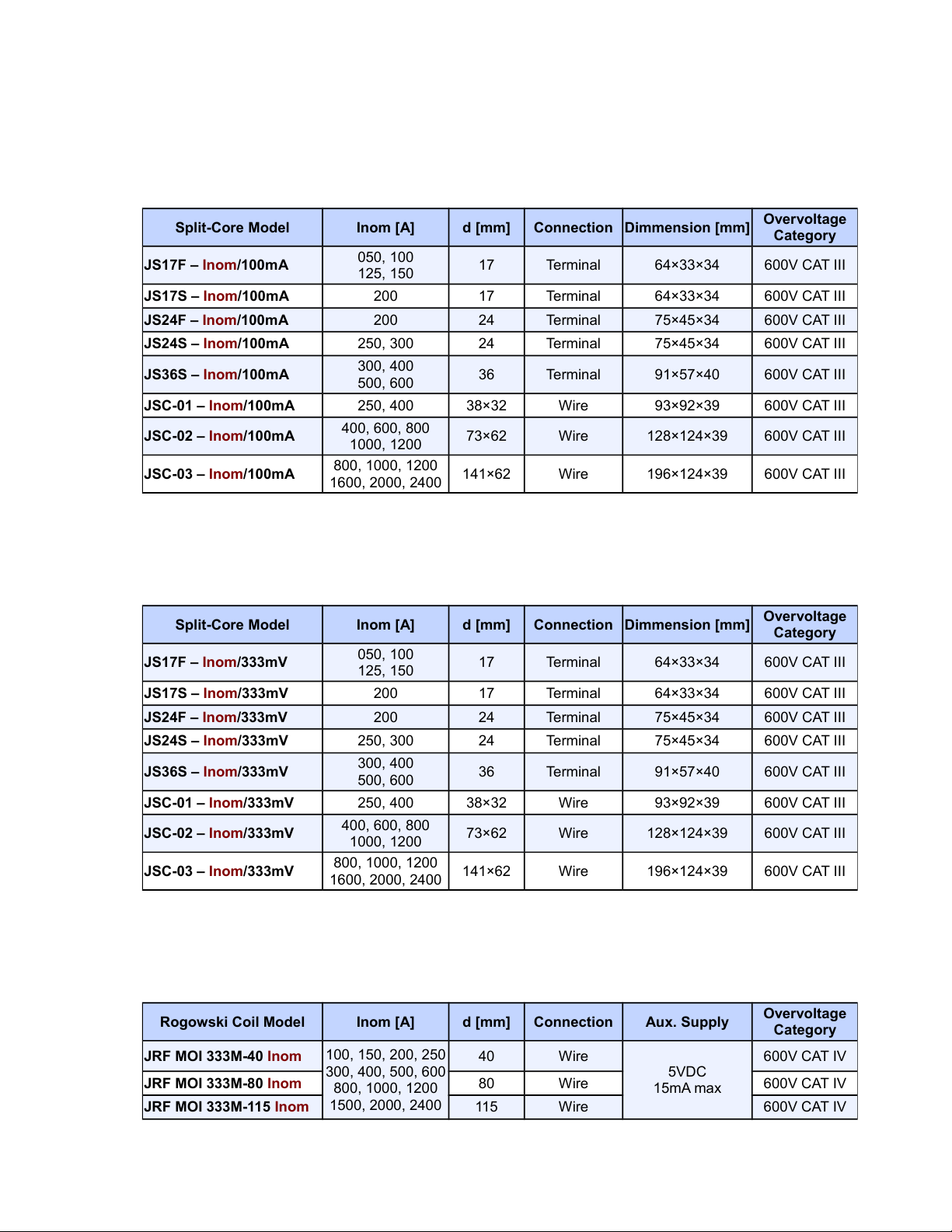
The secondary winding of the split-core transformers is led to the screw terminals. The ”K“/”L“ and ”k“/”l“
orientation is marked on the CT guide groove. A connection cable maximum cross section area is 1.5mm2.
X/333 mV current input option (333mV CT or RCT only) these instruments are supplied with separate
terminal connector for each current input. The current transformers with nominal output voltage 333 mV must
be clamped on measured wires and interconnected with corresponding terminal pairs using a twisted-pair cable
of maximum length of 3 m. Again, proper current signal polarity (k and l terminals) must be observed.
Connection of the current inputs with X/333mV option is shown in fig. 5: terminals SI1, SI2 and SI3 (nr. 62,
65 and 68) are input signals corresponding to currents I1, I2 and I3 (terminal “k” of the measuring CT or white
wire of the RCT). SG terminals (nr. 63, 66 and 69) are a common pole for signals I1, I2 and I3 (terminal “l”
of the measuring CT or black wire of the RCT) and also a negative pole of the internal 5V auxiliary voltage
supply. These terminals are internally interconnected. SP terminals (nr. 61, 64 and 67) are the positive pole of
the internal 5V auxiliary voltage supply for the connected RCT sensors.
Warning !: Connection of unsupported type of current transformer such as the common type
with 5A or 1A secondary to an 333mV option instrument is strictly forbidden! The instrument
can be seriously damaged!
Warning !: Do not connect the current input signals of the 333mV option with neither ground
nor other potential ! Otherwise, measurement accuracy can be affected or the instrument can be
damaged!
The flexible current sensors with embedded integrator usually require a power supply. For such purpose the
instruments are equipped with auxiliary power supply 5V. Maximum load of each sensor connected is 20 mA.
2.2.4 Communication peripherals
USB communication port for USB slave is located on the front panel in its bottom-right corner. This
communication port is intended for easy local configuration and fast download of archived data to the local
PC. Use the supplied USB cable only. SMY 133 is a USB slave device. For correct operation it needs a driver
installed in your operating system (see the ENVIS user guide for more info).
Ethernet interface (optional) 10Base-T Ethernet interface with RJ-45 connector described ETH is situated
on a back side (terminal panel) of the device. Ethernet interface can be used as substitution for the primary
RS-485 for connection of the device to LAN and for easy connection of remote control PC.
RS-485 Serial Line serves usually as a remote communication for reading of actual data, archive downloading
and device configuration. Serial RS-485 line uses terminals A, B and GND (no. 28, 29 and 30 on fig. 3a and 8).
The final points of the communication line must be properly terminated with resistance.
7

SMY 133 U 400 X/5A N 4
L1
L2
L3
N
PE
kl
kl
kl
SMY 133 U 230 X/5A N 4
SMY 133 U 400 X/5A N 4
L1
L2
L3
kl
kl
kl
Option S:
10 ÷ 26VAC
10 ÷ 36VDC
Option U:
85÷275VAC
80÷350VDC
Option L:
20 ÷ 50VAC
20 ÷ 75VDC
SMY 133 S230 X/5A N 4
Figure 4: An example of typical installation of SMY 133 instrument in a low voltage network — option U (left)
with power supplied from the measured channel in a star connection and option S (right) with low voltage DC
power supply, measurement connected as delta connection — based on the power supply option various AC and
DC power supplies can be used including battery backed UPC etc.
SMY 133 U 400 X/5A N 4
L1
L2
L3
N
PE
333 mV CURRENT SIGNAL INPUTS
SI1SP SG SI2SP SG SI3SP SG
SMY 133 U 400 X/5A N 4
L1
L2
L3
N
PE
333 mV CURRENT SIGNAL INPUTS
SI1SP SG SI2SP SG SI3SP SG
Figure 5: Typical installation of a X/333mV option of SMY 133 instrument in a low voltage network with power
supplied independently. Three RCTs (flexible rogowski probes) powered from the instruments internal power
supply (left) or split core current transformers with secondary output 333mV (right).
8

SMY 133 U 400 X/5A N 4
L
N
PE
kl
kl
kl
SMY 133 U 400 X/5A N 4
L1
L2
L3
kl
kl
MV/LV
Transformer L1
L2
L3
N
PE
SMY 133 U 100 X/5A N 4
Figure 6: Special cases of connection for SMY 133 instrument: single phase three wire connection in LV network
and Aron connection commonly used in MV and HV network. .
SMY 133 U 400 X/5A N 4
L1
L2
L3
kl
kl
kl
MV/LV
Transformer L1
L2
L3
N
PE
20V ÷ 75 V DC
24V ÷ 48 V AC
SMY 133 L 100 X/5A N 4
SMY 133 U 400 X/5A N 4
L1
L2
L3
kl
kl
kl
MV/LV
Transformer L1
L2
L3
N
PE
SMY 133 U 100 X/5A N 4
Figure 7: Example of typical connection of SMY 133 in MV or HV network with indirect measurement via
voltage transformers. Option L on left side is supplied from a backup power supply. Option U on the right side
is supplied from L1 of the LV network.
9

28 29 30
A/+
B/-
28 29 30
PE
120 Ω
max. 1200m
Figure 8: Typical wiring of the RS-485 communication line terminals in SMY 133 .
12÷24
VDC
Other Instrument
max.
5mA
L
N
250VAC/5A
max
Relay
Output
Pulse
Output Input
12÷48
VDC
Other Instrument
Pulse
Input
max.
60VDC
100mA
Figure 9: An example of wiring connection for inputs and outputs in SMY 133 .
2.2.5 Outputs and inputs
Instruments can be equipped with optional outputs and inputs. Two digital outputs DO1, DO2 (electromechan-
ical relay or solid-state according to the option), one digital input DI1 and two virtual programmable alarms A1
and A2 are available in the instrument. Outputs are connected to the terminal no. 15 to 18 on the rear panel of
an instrument. Input signal can be connected to terminal nr. 19 and 20. A cable maximum cross section area
is 2.5mm2. Both inputs and outputs are isolated from the instrument internal circuits as well as between each
other.
Digital outputs DO1 and DO2 (optional with RR, RI and II) can be configured to generate pulses
from an electricity meter or other quantity, as a simple programmable two-position controller or as a remote
application controlled output.
Relay output (R) (SPST-NO: single-pole, single-throw, normally open relay) is used. Maximum allowable
voltage and load current according to the technical specifications must be fulfilled.
Impulse output (I) is accomplished by a semiconductor switching device. It is assumed that the input opto-
couplers of the external recording or control system will be connected to these outputs via proper current–limiting
resistors. The signal polarity is not significant to the device.
10

Digital Input DI1 (optional with RR, RI and II) state is indicated on display and in remote software.
Connect a voltage signal of appropriate magnitude to the the DI1 terminals. The signal polarity is not significant
to the device. If the voltage exceeds declared level, the input is activated and the symbol is displayed. Usual
12 or 24 V DC/AC signals can be connected directly. If you need to connect a voltage signal of magnitude
exceeding maximum digital input voltage, an external limiting resistor of appropriate rating must be used.
2.3 Lock/unlock the instrument
From the manufacturer the instrument is shipped in an unlocked state. It is however possible to lock the
instrument so as to prevent any unwanted modifications of its configuration by aliens.
2.3.1 Locking the instrument
1. press the button Âin the default start screen
2. choose lock/unlock symbol with buttons Ãand Ä. Unlocked instrument presents open lock symbol.
3. press button Âand enter the locking/unlocking sub-menu of the instrument. It displays Unlocked:
$
4. press Âand choose lock option. Symbols
"
and
$
will be displayed
5. chose requested new state (
"
...locked) by pressing Ãand Ä
6. confirm your selection with pressing button Â
7. leave the locking screen by pressing button À
8. press button Áand confirm locking of the instrument. Your SMY 133 is now locked and all local modifi-
cations of configuration are not allowed.
2.3.2 Unlocking the instrument
1. press button Âin the default start screen
2. choose lock/unlock symbol with buttons Ãand Ä. Locked instrument presents closed lock symbol
3. press button Âand enter the locking/unlocking sub-menu of the instrument. It displays Locked:
"
4. press Âand choose lock option. PIN code entry field will be displayed on locked instruments
5. enter the PIN code (instrument serial number) by pressing buttons Á,Ãand Ä
6. press button Âto confirm the choice
7. leave the locking menu with button À
8. press button Áand confirm locking of the instrument. Your SMY 133 is now unlocked and all local
modifications are allowed.
11

Figure 10: Screen of the SMY 133 : button À- without function, Á- without function, Â- menu, Ã- up arrow
rotates displayed screens, Ä- down arrow rotates displayed screen. Default start-up screen is on the left.
(a) Main menu of the instrument. (b) Special user defined split screen dis-
plays data compacted.
(c) Graphical display of the measured
harmonics (here phase voltage).
Figure 11: Examples of different actual data displayed on screen of the SMY 133 instrument.
2.4 Basic instrument setup (on screen)
To navigate the screen and to configure the SMY 133 instrument locally there is 5 multifunction buttons located
under the display area. its actual function is dynamic and is symbolized by a pictogram on the lower edge of
the screen above each button (fig. 10). For intention of use in this manual we are referring to these buttons as
button Àto Äfrom left to right.
In general buttons Ãand Äare navigational buttons. Button Âis alternating Confirm function and Return
to main menu function. Buttons Àand Áare either without function or they provide navigation and other
functions in the context of each screen.
2.4.1 Installation type and options
1. turn on the instrument and wait until it boots up. Start-up screen will be displayed (fig. 10).
2. press button Â- main menu is displayed (fig. 11a). Buttons Á,ÃaÄnavigate selection cursor in this
screen. Button Âpicks the highlighted menu item. Button Àreturns back in the menu level.
3. press multiple times button Äand choose settings symbol - green french key.
4. press button Â. Configuration screen will be displayed (fig. 12a)
5. press multiple times button Äand select Install Config item.
6. press button Â.Install Config screen is displayed.
12

(a) Configuration menu of the SMY 133
analyzer.
(b) Setting up the display options. (c) Setting up the basic installation pa-
rameters of an instrument.
(d) Setting up the RS485 serial commu-
nication option.
(e) Setting up the Ethernet communi-
cation option.
(f) Setting up the time, date and time
synchronization options.
Figure 12: Set up screens of the SMY 133 analyzer.
7. select Connection Type according to the physical connection of the instrument.
8. insert correct value of voltage and current transformer ratio according to the used VT and CT.
9. press button Àand accept the settings modifications on a displayed screen.
10. press button Áto confirm the change or button Ãto cancel the previous modifications.
2.4.2 Communication options
1. select the Communication item in menu
2. confirm ETH or RS-485 configuration according to the instrument option
(a) ETH: enter IP address, network mask and gateway. Leave values of protocol port assignments in its
default.
(b) RS-485: enter communication line parameters according to your setup
2.4.3 Time and date options
1. select the Time and Date item in menu
2. enter time and date value, valid at the time of end of editing.
3. select if instrument uses Summer Time option.
4. choose the valid Time Zone
13

Figure 13: Main window of the ENVIS.Daq application - enter communication type, choose its parameters and
click Connect to continue.
Figure 14: Window of Locator tool - provides automatic discovery of the supported instruments in a local
network.
5. Time Synchronization is usually not required.
Now the instrument is configured and is ready to be used in typical application. Advanced configuration options
are described in detail in chapter 2.5.
2.5 Detailed configuration of SMY 133 on a PC
To begin a measurement it is recommended to configure the SMY 133 instrument appropriately. This setting is
done by PC with an ENVIS.Daq2application.
Warning! This setting will erase all previously archived data in memory of the instrument.
Before writing new configuration to the device make sure to backup the last measured archive.
1. Turn on the instrument. Under normal conditions the unit will boot up and display its predefined initial
screen.
2. Connect the SMY 133 to a computer via USB3, RS-485 or Ethernet interface. Now the unit is ready to
2The ENVIS.Daq application is used for configuration of the instrument. This software is available for download form
WWW.KMB.CZ as a part of ENVIS installation package or as a standalone application. Detailed description can be found in
The ENVIS User Guide.
3If a USB instrument is connected to the PC for the first time it is necessary to install its driver in Windows. You can find
the actual driver for our instruments online on the the WWW.KMB.CZ website. It is also located in the driver folder of ENVIS
software installation folder, for example in: ’C:\Program Files (x86)\KMB systems\ENVIS 1.2\driver’
14

Figure 15: ENVIS.Daq application connected to the instrument.
be configured.
3. Run ENVIS.Daq application and pick the appropriate tab for the given communication line.
4. Fill in communication line parameters. A connection form with typical parameters is shown in figure 13.
(a) USB: choose the correct virtual communication port from the list
(b) RS485: Select the correct serial port from a list and set up communication line baud rate.
(c) Ethernet: enter correct IP address and port (default: 2101). If you do not know the right values you
can use Locator4(fig. 14).
(d) Edit an address of the instrument (Default: 1)
(e) Enter the device type: KMB
5. Press the Connect button or the ENTER key. application will attempt to connect to the instrument. In
case of successful connection it reads the configuration from the instrument and displays new window with
summary information (figure 15).
6. Press the Settings button in left column. New window with actual instrument settings will be opened.
Category Instrument Settings includes sub-categories, sorted and grouped in various tabs. Changes in configura-
tion are only performed in the windows application. To the instrument they are sent with a Send button.With
4Locator is a tool for automatic look-up of the instruments in a local network or on a serial line. Caution: it contains special
functions such as an embedded DHCP server, which can severely interfere with the normal operation of Ethernet network. It also
might need a customization of your PC firewall to work correctly.
15

button Receive user can re-read the stored configuration from a device. This will effectively cancel all the local
modification in the application. Unwritten changes in configuration on each tab is signalized by an exclamation
sign. Buttons Save and Load provide a possibility to archive the actual settings to a file.
For correct operation an appropriate configuration of at least Installation and Time and Date tab is crucial.
2.5.1 Installation (fig.16)
Nominal Frequency - defines the nominal network frequency measured at 50 or 60 Hz. It also influences,
how power quality indice are evaluated.
Connection Mode - the way of connection of the instrument to the measured voltage — either direct voltage
measurement or via voltage transformers (usually in a HV network).
Connection Type - type of measured network according to the actual connection - three-phase star, three-
phase delta or Aron connection. Supported connections schema are in fig. 16b and 16c for illustration.
UNOM ,PN OM (rated voltage and power) — correct configuration of these values influences relative values
used on display and in condition evaluation (alarms, PQ evaluation, IO, ENVIS data processing).
–UNOM is a nominal (primary) voltage of the measured network
–PNOM is a nominal power given by the system transformer or used protection device.
VT Ratio, VTN Ratio - sets the conversion ratio of voltage inputs for Connection Mode: via VT measure-
ment. Must be set accordingly to the primary and secondary rating of the measuring voltage transformer
(transfer ratio). ’VTN’ designates the optional fourth voltage input, available with some Connection Types.
–nominal primary voltage: default value for ’via VT’ option is 22 000 V.
–nominal secondary voltage: default value is 100 V (other common values are 110, 120, 230V)
CT Ratio, CTN Ratio - sets the conversion ratio of current input. ’CTN’ designates the fourth input,
usually a neutral wire.
–For standard instruments with X/5A and X/1A is specified as a ratio between primary and secondary
current. Default value is 100 A/5A resp. 1 A.
–For SMY 133 options X/100mA and X/20mA a nominal primary and nominal secondary current of
the supplied transformer is used. Default value is 100 A/100 mA resp. 20 mA.
–
Multiplier U : this parameter is usually not necessary. Default value is 1. In special cases it can be used to
correct the ratio of measured voltage.
Multiplier I - this parameter is usually not nescessry. Default value is 1.
–in case of direct current measurement (fig. 4) leave the Multiplier I in its default value:1.
–in case of indirect current measurements with nonstandard conversion ratio (multiple loops of mea-
sured wire through the measuring transformer etc) specify the new ratio as a fraction5to which you
need to multiply the original conversion ratio to get the real measured value of current.
5If, for example, primary CT with ratio 100/5 is used, set multiplier to 100
5= 20. Another example, when Multiplier I can
be used, is winding more than one loop of measured conductor through current transformer for sensitivity extension (and range
reduction). For example for 4 loops Multiplier I should be set to 1
4= 0.25.
16

(a) Configuration of basic installation parameters in ENVIS.Daq.
(b) Instrument connection types for direct measurement (in LV networks).
(c) Instrument connection types for indirect measurement — to be connected via VT (in HV networks).
Figure 16: ENVIS.Daq - configuration of the device installation.
17
Other manuals for SMY 133
2
Table of contents
Other KMB Measuring Instrument manuals