Contents
1 Features ..........................................................................................................................................................................3
2 Overview ........................................................................................................................................................................4
2.1 System Components .......................................................................................................................................................................5
2.2 Models ..............................................................................................................................................................................................5
2.3 Status Indicators ............................................................................................................................................................................. 5
2.3.1 Zone Indicators (Beams Blocked Segment) ............................................................................................................................ 6
2.3.2 Three-Digit Display .................................................................................................................................................................. 6
2.3.3 Blanking Indicator .................................................................................................................................................................... 6
2.3.4 Electronic Configuration Indicator ............................................................................................................................................6
3 Configuration via DIP Switch or IO-Link v1.1 Interface ..............................................................................................8
3.1 Receiver Gray (Remote Teach) Wire ..............................................................................................................................................8
3.2 Gain Configuration ........................................................................................................................................................................... 9
3.3 Blanking ........................................................................................................................................................................................ 10
3.4 Measurement Mode Selection ...................................................................................................................................................... 10
3.5 Outputs ...........................................................................................................................................................................................13
3.5.1 Analog Output Configuration ................................................................................................................................................. 13
3.5.2 Discrete Output Configuration ............................................................................................................................................... 13
3.6 Scanning Method .......................................................................................................................................................................... 13
3.6.1 Straight Scan ......................................................................................................................................................................... 14
3.6.2 Single-Edge Scan ..................................................................................................................................................................14
3.6.3 Double-Edge Scan ................................................................................................................................................................ 14
3.6.4 Maximum Scan Times in SIO Mode ....................................................................................................................................... 15
4 Installation Instructions ............................................................................................................................................. 16
4.1 Mounting the Emitter and Receiver ...............................................................................................................................................16
4.2 Mechanical Alignment ...................................................................................................................................................................16
4.3 Wiring Diagrams .............................................................................................................................................................................18
4.4 Optical Alignment ..........................................................................................................................................................................19
5 Receiver User Interface ..............................................................................................................................................21
5.1 Configuration DIP Switches .......................................................................................................................................................... 21
5.1.1 Scanning Modes (S1 and S2) ................................................................................................................................................22
5.1.2 Measurement Modes (S3 and S4) .........................................................................................................................................22
5.1.3 Analog Slope (S5) .................................................................................................................................................................. 22
5.1.4 Complementary/Alarm (S6) ................................................................................................................................................... 22
5.2 Alignment/Blanking Button (Electronic Alignment) ........................................................................................................................22
5.2.1 Electronic Alignment and Blanking - Receiver Interface ........................................................................................................23
5.2.2 Flashing "000" on the 3-Digit Display .................................................................................................................................... 23
5.3 Gain (Sensitivity Adjust) Button .....................................................................................................................................................23
5.4 Inverting the 3-Digit Display ........................................................................................................................................................... 23
6 Additional Information ............................................................................................................................................... 24
6.1 IO-Link Overview ...........................................................................................................................................................................24
6.2 IO-Link v1.1 Profile and Models .....................................................................................................................................................24
6.3 Hardware Interface ........................................................................................................................................................................24
6.3.1 Electrical Interface ................................................................................................................................................................. 24
6.3.2 IO-Link Master ....................................................................................................................................................................... 25
6.4 IODD (IO-Link Device Description) and Parameters ......................................................................................................................25
7 Troubleshooting ......................................................................................................................................................... 26
7.1 Error Codes ....................................................................................................................................................................................26
7.2 "Dirty" Channel Indicator ...............................................................................................................................................................26
8 Specifications .............................................................................................................................................................. 27
8.1 Emitter and Receiver Dimensions ..................................................................................................................................................28
8.2 Standard Bracket Dimensions .......................................................................................................................................................29
9 Accessories ..................................................................................................................................................................30
9.1 Cordsets and Connections ............................................................................................................................................................30
9.2 Alignment Aids ............................................................................................................................................................................... 31
9.3 Accessory Mounting Brackets and Stands ....................................................................................................................................32
10 Product Support and Maintenance ......................................................................................................................... 33
10.1 Replacement Parts ......................................................................................................................................................................33
10.2 Contact Us ................................................................................................................................................................................... 33
10.3 Banner Engineering Corp. Limited Warranty .............................................................................................................................. 33
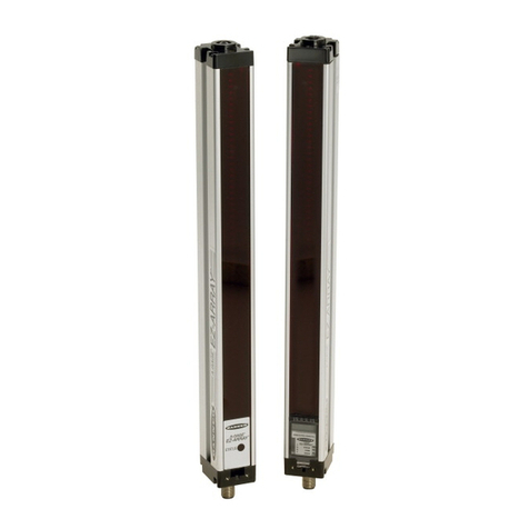
A-GAGE® EZ-ARRAY™ with IO-Link v1.1
