Diamond Tools ICS 701-A Series User manual

Model # 701-A
OPERATOR’S MANUAL

© 2021 ICS, Oregon Tool International Inc. Specications are subject to change without notice. REV10152021 F/N 573498
701-A SERIES OPERATOR’S MANUAL
2
INTRODUCTION
This manual outlines the maintenance and operation of ICS®manufactured
products.
This is a professional tool and is solely intended for use by trained and
experienced operators.
The 701-A Series power cutter is designed to cut concrete, stone, and
masonry when used with the appropriate genuine ICS Diamond Chain. Other
materials including ductile iron, cast iron or PVC pipe require the use of ICS
PowerGrit®Utility Chain.
To get the maximum benefit from your power cutter, and ensure maximum
safety, be sure to read this manual thoroughly, and periodically review safety
instructions.
INTRODUCTION

701-A SERIES OPERATOR’S MANUAL
© 2021 ICS, Oregon Tool International Inc. Specications are subject to change without notice. REV10152021 F/N 573498
3
TABLE OF CONTENTS
SYMBOLS & LABELS 4 - 5
NAMES & TERMS 6 - 7
SAFETY 8 - 10
TECHNICAL SPECIFICATIONS 11
SET-UP 12 - 17
OPERATION 18 - 23
TROUBLESHOOTING 24
MAINTENANCE 25-26
REFERENCE 27
DECLARATION OF CONFORMITY 28
TABLE OF CONTENTS

© 2021 ICS, Oregon Tool International Inc. Specications are subject to change without notice. REV10152021 F/N 573498
701-A SERIES OPERATOR’S MANUAL
4
SYMBOLS & LABELS
SAFETY RULES
To get the maximum benet from your power cutter, and ensure maximum
safety, be sure to read this manual thoroughly and follow the safety instructions
provided.
EXPLANATION OF WARNING LEVELS
IMPORTANT
Indicates a hazard with a medium level of risk which, if not avoided, could result
in death or serious injury.
Indicates a hazard with a low level of risk which, if not avoided, could result in
minor or moderate injury.
Indicates a potential situation exists which, if not avoided, may result in damage
to your power cutter or property.
Indicates a hazard with a high level of risk which, if not avoided, will result in
death or serious injury.
WARNING
CAUTION
DANGER
Model 701-A
Serial # XXYYZZZZ
Blount, Inc.
4909 SE International Way
Portland, OR 97222 USA
ZZZZ = Power cutter number within
production batch in sequential order
beginning with 0001
YY = Month of Manufacture (ie. 07)
XX = Year of Manufacture (ie. 15)
113
MAX
124 cfm /3.5 m /min
90 psi / 6 bar
3

701-A SERIES OPERATOR’S MANUAL
© 2021 ICS, Oregon Tool International Inc. Specications are subject to change without notice. REV10152021 F/N 573498
5
SYMBOLS & LABELS
SYMBOLS AND LABELS
THE FOLLOWING SYMBOLS ARE FOUND THROUGHOUT THIS MANUAL
AND/OR ON THE POWER CUTTER AND ARE DESIGNED TO MAKE
YOU AWARE OF POTENTIAL HAZARDS OR UNSAFE PRACTICES.
SAFETY ALERT
Indicates that the
text that
follows explains a
danger,
warning or caution.
READ
INSTRUCTIONS
The original
instruction manual
contains important
safety and operating
information. Read
and follow the
instructions carefully.
WEAR
PROTECTION
Wear eye , hearing
and respiratory
protection and a
protective helmet
when operating the
power cutter.
BEWARE OF
KICKBACK
Kickback can cause
severe injuries.
TWO-HANDED
HOLD
Operate the power
cutter with two
hands, securely
gripping both
handles
WEAR LONG
PANTS
Wear long pants
when operating the
power cutter.
WEAR FOOT
PROTECTION
Wear appropriate
closed-toe boots
when operating the
power cutter.
WEAR HAND
PROTECTION
Wear hand
protection when
operating the power
cutter.
ONE-HANDED
HOLD
Do not operate the
power cutter with
only one hand.
DO NOT USE A
LADDER
Never stand on a
ladder when using
the power cutter.
113
KERF WIDTH
Do not insert tool
into slot
narrower than chain.
PNEUMATIC
POWER
SOUND POWER
Sound power level
is 113 dB(A).
FIRE DANGER
Risk of re if
warnings not
followed.
SLIPPERY
SURFACE
Unsure footing can
lead to
accidents.

© 2021 ICS, Oregon Tool International Inc. Specications are subject to change without notice. REV10152021 F/N 573498
701-A SERIES OPERATOR’S MANUAL
6
NAMES & TERMS
.444 ÷2
=
determine chain pitch
701-A NAMES AND TERMS
Bae Drain
A device for controlling slurry and cutting debris in the side cover to
reduce chain stretch and protect the operator from other projectiles.
Bar retaining plate
The plate between the guidebar and side cover that clamps the guidebar
to prevent movement during operation.
Bar pad
The mounting pad on the powerhead that helps assure proper alignment
of the guidebar.
Bar slot
The slot feature on the guidebar that ts over the alignment block and bar
stud.
Bystander safety zone
A 6 m (20 ft) circle around the operator that must remain free from
bystanders, children and pets.
CFM
CFM stands for cubic feet per minute. This is the air ow or air volume that
a compressor can supply – or its output.
Chain catcher
A device for retaining the chain if it breaks or derails.
Chain pitch
The distance between any three consecutive rivets on
the chain divided by two.
Chain tensioning screw
An adjustment screw used to set proper tension on the
chain and compensate for chain stretch from normal use.
Front handle
The support handle located at or toward the front of the power cutter
intended to be gripped by the left hand.
Guidebar
A railed structure that supports and guides the chain. Sometimes simply
called the “bar”.
GPM
GPM means Gallons Per Minute. Also known as “ow rate”, GPM is a
measure of how many gallons of water ow out of your water hose
each minute.
Kickback
The rapid backward and/or upward motion of the guidebar, occurring when
the chain near the top area of the nose of the guidebar contacts a foreign
object or snags in the workpiece.
LPM
LPM means Liters Per Minute. Also known as “ow rate”, LPM is a measure
of how many liters of water ow out of your water hose each minute.

701-A SERIES OPERATOR’S MANUAL
© 2021 ICS, Oregon Tool International Inc. Specications are subject to change without notice. REV10152021 F/N 573498
7
SYMBOLS & LABELS
Mud ap
A barrier to protect the operator from cutting debris and other projectiles.
Powerhead
A power cutter without the chain or guidebar.
PSI
PSI means pounds per square inch. It measures how much force is in a
certain area – one pound-force applied to one square inch.
Pushback
The rapid backward motion of the guidebar, occurring when the chain on
the top straight portion of the guidebar contacts a foreign object or
snags in the workpiece.
Rear handle
The support handle located at or toward the rear of the power cutter
intended to be gripped by the right hand.
Rear hand guard:
A structural barrier at the bottom right side of the rear handle to protect the
operator in case the chain breaks or derails.
Side cover:
The component on the powerhead that covers the drive sprocket and
directs debris away from the operator during use.
Side cover nut:
The component on the side cover that secures the side cover and guide-
bar.
Throttle trigger lock-out
A device that prevents the unintentional operation of the throttle trigger
until manually released.
Throttle trigger
A mechanism that controls engine RPM.
WallWalker®
A device used as a fulcrum to provide mechanical advantage during cut-
ting.
Water shut-o valve
A mechanism that controls water delivery and ow to the guidebar and
chain.

© 2021 ICS, Oregon Tool International Inc. Specications are subject to change without notice. REV10152021 F/N 573498
701-A SERIES OPERATOR’S MANUAL
8
THE FOLLOWING WARNING SYMBOL APPLIES TO ALL THE ITEMS LISTED
ON THIS PAGE
Note: Chain breakage can result in high-speed ejection of parts, which
can result in death or serious personal injury to operators or bystanders.
The items listed immediately below are critical to minimizing the risk of
chain breakage and injury.
• DO NOT operate the power cutter with damaged, modied or missing
components shown below.
• Side cover
• Mud ap
• Rear hand guard
• Mud ap bracket (chain catcher)
• Trigger interlock
• DO NOT exceed 90 psi (6 bar) operating pressure.
• DO NOT insert the diamond chain power cutter into a slot narrower
than the chain segments.
Rapid pushback might occur.
NOTE: Most ICS diamond chain segments are .225 inches (5.72 mm) wide.
• NEVER run a diamond chain power cutter upside-down.
Concrete debris can y back into the operator’s face.
• NEVER cut ductile iron pipe with concrete chain.
Segment loss or chain breakage may occur.
• NEVER operate the ICS power cutter with a saw chain or saw bar
designed to cut wood.
Using wood cutting saw chain on the ICS power cutter could result in
severe injuries to operator and bystanders! Use ONLY the cutting
attachments specied in this manual on this power cutter.
SAFETY
WARNING Indicates a hazard with a medium level of risk
which, if not avoided, could result in death or
serious injury.

701-A SERIES OPERATOR’S MANUAL
© 2021 ICS, Oregon Tool International Inc. Specications are subject to change without notice. REV10152021 F/N 573498
9
SAFETY
THE FOLLOWING WARNING SYMBOL APPLIES TO ALL THE ITEMS LISTED
ON THIS PAGE
This power cutter can generate hazardous dust and vapors.
Determine the nature of the material you are going to cut before
proceeding with the job. Be especially aware of cutting materials containing
silica and asbestos as inhaling dust can result in respiratory disease. Be sure
to use appropriate respiratory protection designed to lter out microscopic
particles. Be sure to use adequate water pressure.
Over-exposure to vibration can lead to circulatory and/or nerve damage to
the extremities, especially in cold temperatures (Reynaud’s Disease).
If you experience tingling, numbness, pain or changes in skin color, particularly
in your ngers, hands or wrists, stop using the power cutter immediately. If the
problem persists, seek medical attention.
WARNING Indicates a hazard with a medium level of risk
which, if not avoided, could result in death or
serious injury.

© 2021 ICS, Oregon Tool International Inc. Specications are subject to change without notice. REV10152021 F/N 573498
701-A SERIES OPERATOR’S MANUAL
10
• Always disconnect the air supply and relieve pressure from supply lines
before performing maintenance on the power cutter.
• Diamond chains and guidebar require a minimum water pressure of 20 psi
(1.4 bar). Insucient water supply may result in excessive wear to the
guidebar or diamond chain, which can lead to loss of strength and diamond
chain breakage and damage the bar.
• When operating a compressor with greater than 90 psi (6 bar) it is
recommended to use a “service unit with pressure regulator” in line to
prevent over speeding the power cutter.
GENERAL SAFETY PRECAUTIONS
• Always wear protective clothing, including a hard hat, eye protection, hearing
protection and gloves.
• Avoid loose clothing.
• Perform safety checks before starting each day.
• Always operate tool with solid footing and handgrip.
• Remove or control slurry to prevent yourself or others from slipping while
cutting.
• Always work in a cleared area.
• Be sure there are no obstructions (plumbing, electrical conduit, air ducts).
• Set up a well-marked safety zone with a roped boundary and clear signs to
keep bystanders at least 20 ft (5m) away.
• Breathing exhaust fumes is dangerous. Provide ventilation in closed areas.
• To avoid electrocution, check for live electrical wiring near cutting area.
THE FOLLOWING WARNING SYMBOL APPLIES TO ALL THE ITEMS LISTED
ON THIS PAGE
SAFETY
CAUTION Indicates a hazard with a low level of risk which,
if not avoided, could result in minor or moderate
injury.

701-A SERIES OPERATOR’S MANUAL
© 2021 ICS, Oregon Tool International Inc. Specications are subject to change without notice. REV10152021 F/N 573498
11
TECHNICAL SPECIFICATIONS
Weight without bar and chain 29 lbs (13 kg)
Length 20 in (58.5 cm)
Height 10.5 in (26.5 cm)
Width 12 in (30.5cm)
Air Motor Power 6.5 Hp (5 Kw)
Allowable Air Pressure 90psi (6 bar) maximum
Air Supply Requirement
@ 90psi (6 bar) 124 cfm (3.5 m3/min) minimum
Motor lubrication requirements Resin and acid-free
SAE 5 W to SAE 10 W oil
Water Pressure Requirements Minimum: 20 psi (1.4 bar)
Water Flow Requirements 1 gpm (4 lpm) minimum
Operating Speed 5,700 rpm (average free running)
4,900 sfm (average free running chain)
Vibration ahv, eq Concrete Cutting (2) Front handle: 5.09 m/s2(K=0.2 m/s2)
Rear handle: 5.07 m/s2(K=0.2 m/s2)
Vibration ahv, eq PowerGrit Cutting (2) Front handle: 4.58 m/s2(K=0.2 m/s2)
Rear handle: 4.43 m/s2(K=0.2 m/s2)
Guaranteed Sound Power Level Lwa (1) 113 dB(A); (Kwa=0.5 dB(A))
• When operating a compressor with pressure greater than 90 psi (6 bar) it is
recommended to use a “service unit with pressure regulator” in the line to prevent over
speeding the power cutter.
• Always use an in-line oiler (ICS p/n 575130) or air pac (ICS p/n 597279) to provide continuous
lubrication to the air motor. This will increase the life of the power cutter and reduce down time.
(1) Measured in accordance with ANSI S12.51-2012/ISO3741:2010
(2) Measured in accordance with ISO5349-1:2001 and ISO22867:2011
© 2021 ICS, Oregon Tool International Inc. Specications are subject to change without notice. REV10152021 F/N 573498
701-A SERIES OPERATOR’S MANUAL
12
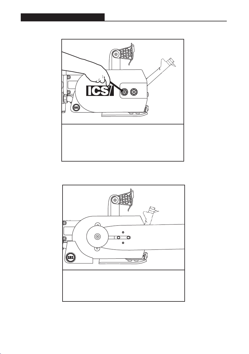
STEP 1
Loosen the side cover nuts and remove
the side cover and bar clamp plate.
STEP 2
Place the bar onto the studs and the chain
adjustment pin.
SET-UP
701-A SERIES OPERATOR’S MANUAL
© 2021 ICS, Oregon Tool International Inc. Specications are subject to change without notice. REV10152021 F/N 573498
13
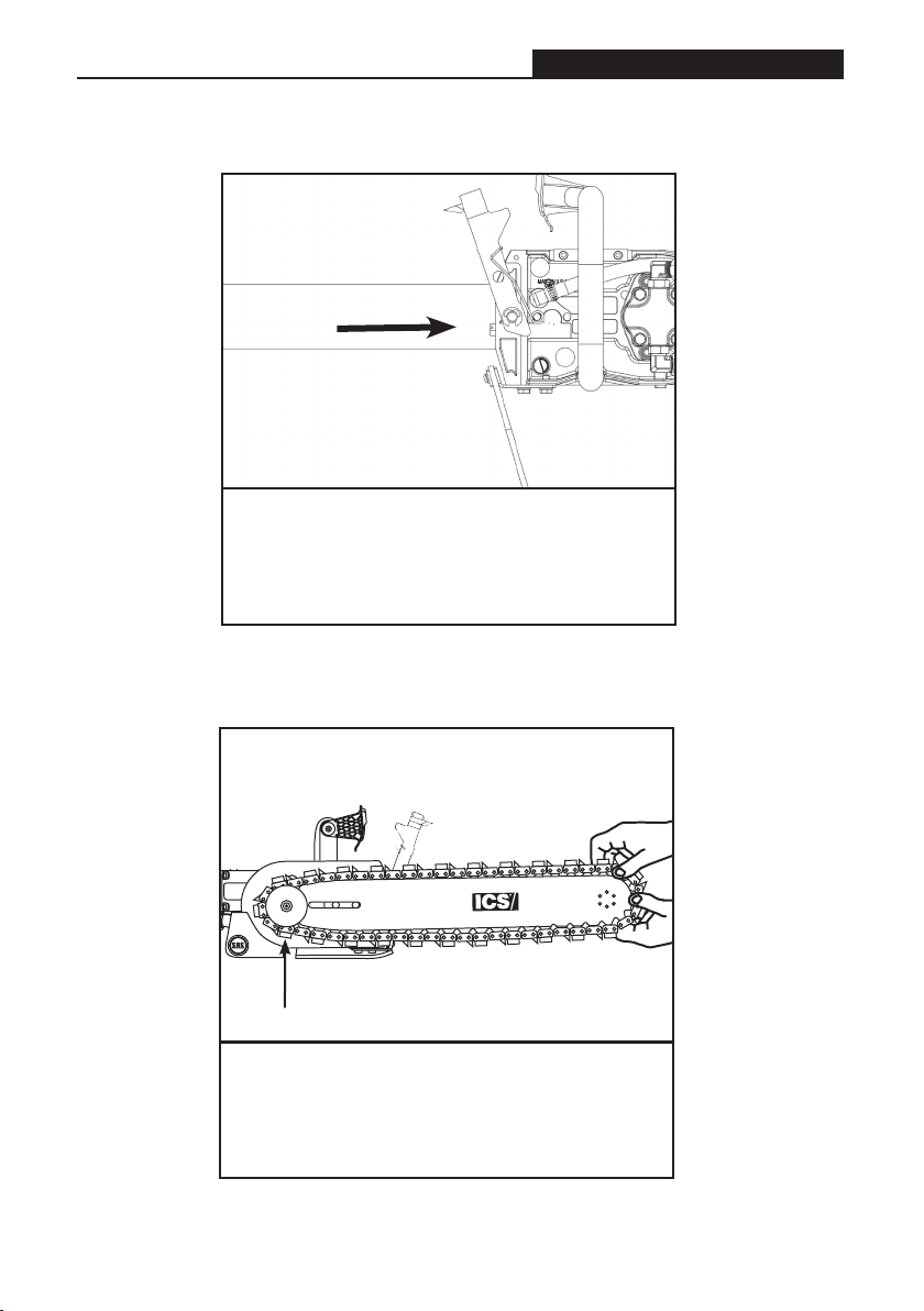
STEP 3
Turn the chain-tensioning screw
counterclockwise until the bar comes into
contact with the drive sprocket.
STEP 4
Mount the chain on the bar starting at
the drive sprocket & continue over the
bar nose.
SET-UP
start here
© 2021 ICS, Oregon Tool International Inc. Specications are subject to change without notice. REV10152021 F/N 573498
701-A SERIES OPERATOR’S MANUAL
14
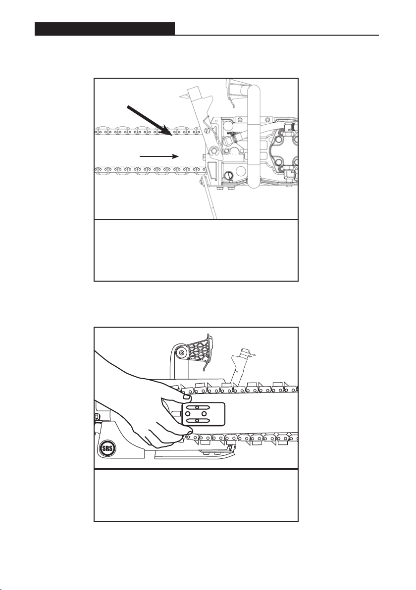
STEP 5
Make sure all of the drive links are inside
the bar groove, then pre-tension the chain
by turning the tensioning screw clockwise.
SET-UP
STEP 6
Install the bar clamp plate over the
bar studs in proper orientation. "Front" is
marked on the plate.

701-A SERIES OPERATOR’S MANUAL
© 2021 ICS, Oregon Tool International Inc. Specications are subject to change without notice. REV10152021 F/N 573498
15
STEP 7
Install the side cover over the bar studs
and install side cover nuts. Finger
tighten only.
STEP 8
Tension the chain properly. Do not over
tension the diamond chain. Loss of power
will result.
SET-UP

© 2021 ICS, Oregon Tool International Inc. Specications are subject to change without notice. REV10152021 F/N 573498
701-A SERIES OPERATOR’S MANUAL
16
CORRECT CHAIN TENSION
All chains have a tendency to stretch
when used. Diamond chains stretch
more than wood cutting chains
because of the abrasive materials
they are cutting.
If the chain is too tight, more power
goes into turning the chain rather
than into the cut. In extreme
over-tightened cases, the power
cutter may not be able to turn the
chain at all. In addition, damage can
occur to the bar nose and premature
stretch may occur.
CHAIN TOO LOOSE
If the chain is too loose, it could come
off the bar, or it will allow the drive
sprocket to spin without turning the
chain, which can damage drive links.
When a chain stretches to a point
where the drive links are hanging
approximately 1/2 in (12 mm) to 3/4
in (18 mm) below the bar, it is time to
tension the chain.
CORRECT CHAIN TENSION
CHAIN TOO TIGHT CHAIN TOO LOOSE
CHAIN TOO TIGHT CHAIN TOO LOOSE
SET-UP
IMPORTANT
CAUTION
CAUTION

701-A SERIES OPERATOR’S MANUAL
© 2021 ICS, Oregon Tool International Inc. Specications are subject to change without notice. REV10152021 F/N 573498
17
STEP 9
Lift up on the nose of the bar and firmly
tighten the side cover nuts. Be sure
the side cover nuts are tightened to
approximately 20 ft-lbs (27 Nm).
SET-UP

© 2021 ICS, Oregon Tool International Inc. Specications are subject to change without notice. REV10152021 F/N 573498
701-A SERIES OPERATOR’S MANUAL
18
OPERATION
PRE-CUT CHECKLIST
ADDITIONAL TENSIONING TIPS:
1. To reduce chain stretch and tensioning downtime, use 20 psi (1.5 bar) or
greater water pressure.
2. Oil the chain at the end of the day to prevent rust but be careful not to over
tension in this condition.
3. When pulling the chain around the bar by hand, be sure to wear gloves. The
bar rails can be very sharp. Grab only the diamond segments to pull the
chain.
4. Always pull the chain away from the WallWalker®. The point of the
WallWalker can also be very sharp.
PROPER CHAIN TENSION
Concrete cutting power cutters operate with looser chain tension than wood
chainsaws. It is common, especially on gas powered, concrete cutting
power cutters to have the drive links hang completely out of the bar. Concrete
cutting power cutters require water for cooling and flushing the cut. Rotating
the chain completely around the bar freely by hand will let you know you have
the chain properly tensioned.
Before tensioning chain, always turn the compressor off and relieve system
pressure before disconnecting from the compressor.
To maximize the life of the cutting system, ensure that proper chain
tension is maintained.
If tension is too tight, it will lead to excessive chain stretch, and a lot of the
power cutters power will be used to overcome friction. In severe cases the
chain may not turn at all and can lead to chain breakage. If the tension is set
too loose, the chain could be thrown off of the bar, or allow the sprocket to
turn with out turning the chain, which will damage the drive links.
WARNING
CAUTION

701-A SERIES OPERATOR’S MANUAL
© 2021 ICS, Oregon Tool International Inc. Specications are subject to change without notice. REV10152021 F/N 573498
19
PRE-CUT CHECKLIST, CONT.
• Adequate Water Supply and Pressure:
Minimum Flow: 1 gpm (4 lpm)
Minimum Water Pressure: 20 psi (1.4 bar)
Checking for water pressure without a pressure gauge: With the compressor
o, attach water hose to the power cutter water connection. Pull the chain
o to one side of the bar and turn on the water valve. If there is a minimum of
20 psi, water should spray 1 - 3 ft (.3 to 1 m) from the bar.
• Proper Air Supply to the Power Cutter:
Allowable Air Pressure: 90 (6 bar) maximum
Air Supply Requirement @ 90psi (6 bar): 124 cfm (3.5 M3/min) minimum
Insure the air supply line is clear before connecting it to the power cutter.
Dirt and water separators are recommended to prevent rust and
condensation from forming in the air lines.
• Motor Lubricator: (Not Included)
Always use an in-line oiler to provide continuous lubrication to the air
motor. The air lubricator or combination lubricator/air drier must be placed 6
to 12 feet (2 - 4 meters) from the tool. This will increase the life of the power
cutter and reduce down time.
Check oil level, when necessary; ll with resin and acid-free SAE 5 W to
SAE 10 W oil.
In winter or when using very moist air, use antifreeze lubricant, such as “ICS
Prolube ATL/AF”, “Killfrost” “BP Energol AX10” or “Kompranol”
OPERATION

© 2021 ICS, Oregon Tool International Inc. Specications are subject to change without notice. REV10152021 F/N 573498
701-A SERIES OPERATOR’S MANUAL
20
PLANNING THE CUT
• Select the proper chain for the material being cut.
• Outline the cut with a permanent marker for a visual cutting guide.
• Avoid pinching the bar and chain. Always cut the bottom of an opening rst,
then top, and then the sides. Save the easiest cut for last.
OPERATION
If cutting pipe with PowerGrit® be sure the cut line stays open by providing
proper pipe support. Also check for neighboring utilities or obstructions.
Concrete is very heavy, 1 cubic foot (30 cubic cm) weighs 150 lbs (68 kg). Be
sure to cut so that concrete cannot fall and injure operator or bystanders.
Check for live electrical wiring near the cutting area or in the concrete to
avoid electrocution which can result in death or serious personal injury.
WARNING
• When cutting reinforced concrete, be sure you are always cutting
concrete as well as rebar. This will prevent the segments from glazing
over and keep the diamonds exposed. Also, expect less chain life when
cutting concrete with heavy rebar.
• When replacing a chain, ip the guidebar over and dress your
guidebar rails to maintain straight cuts. Guidebar rails can be dressed
with a at le or belt sander.
• Note: The normal life of a guidebar is 2 to 3 chains. However, heavy
rebar can shorten guidebar life too.
• When using a new chain, cutting speed can be increased by
“opening up the diamonds”. Make a few plunge cuts in an abrasive
material such as a cinder block.
Wear gloves when handling the bar and chain. Over time, these components
can develop sharp edges and cause cuts.
CAUTION
Table of contents


