Raytools BM109 SERIES User manual

BM109 SERIES
Hotline: 400-670-1510
Email: sales@empower.cn
Add: No.72, Lane 1500, Xinfei Road, Songjiang District, Shanghai
1500W Auto-Focusing Laser Cutting Heads User Manual

V1.0 Shanghai Empower Technologies Co., Ltd. © Copy Right 1 | 24
www.empower.cn
BM109 SERIES 1.5KW Auto-Focusing Laser Cutting Heads
User Manual
Version:
V1.0
Date:
2018/03/26
Historical Version:
Historical
Version
Release
date
Change the profile
Editors
Editing date
Reviewers
Review
date
V1.0
2018/03/26
Establish BM109 User Manual
Yuan
Jiaxin
2018/03/26
Alex Li
2018/03/2
6
Thank you for your choosing our product!
This manual makes a detail introduction about the use of BM109 laser cutting head, including
installation, setup, operation and service etc. Please directly contact us if you have other things to
know.
Please read these instructions carefully before use the series cutting head and relative equips.
This will help you to use it better.
Because the product keeps renewing, please note the product you receive may differ slightly
from the illustrations in this manual in some aspects. We apologize for your inconvenience here.

V1.0 Shanghai Empower Technologies Co., Ltd. © Copy Right 2 | 24
www.empower.cn
BM109 SERIES 1.5KW Auto-Focusing Laser Cutting Heads
User Manual
Contents
1 Summary.......................................................................................................................................... 4
1.1 Product Advantages ..............................................................................................................4
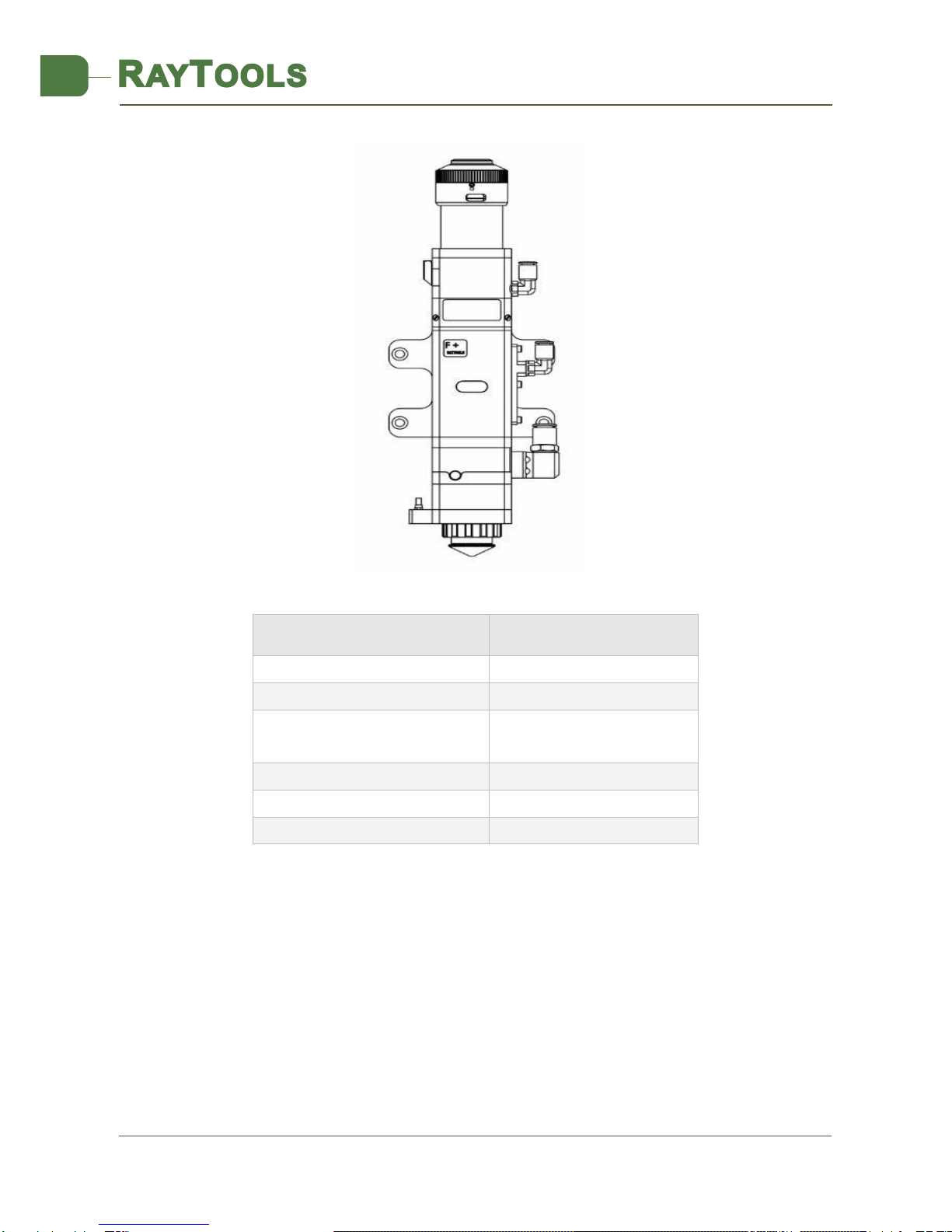
1.2 Structure & Function ............................................................................................................5
2 Machinery Installation ..................................................................................................................... 6
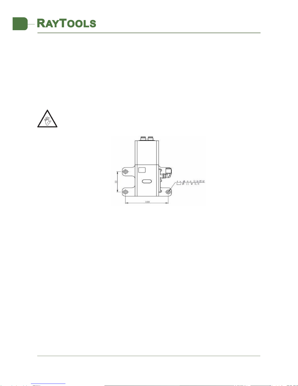
2.1 Hole Site installation .............................................................................................................6
2.2 Connection of Water Pipe and Gas Pipe...............................................................................6
2.2.1 Water-cooled Interface .................................................................................................6
2.2.2 Assist Gas Interface....................................................................................................7
2.3 Connection of Cutting Head Cable........................................................................................8
2.3.1 Connection of Cutting Head and Cable.........................................................................8
2.3.2 Connection Cable and Driver Connection..................................................................9
2.4 Fiber Input Interface .............................................................................................................9
2.5 Fiber Insertion and Interface Direction Adjustment.............................................................9
3 System Installation Commissioning ............................................................................................... 11
3.1 Non-bus Position Loop-BC ..................................................................................................11
3.1.1 Distribution .................................................................................................................11
3.1.2 Software Settings ........................................................................................................12
3.1.3 Interface Operation.....................................................................................................12
4 Beam Adjustments and Focusing...................................................................................................14
4.1 Beam Adjustments (QBH Interface)....................................................................................14
4.2 The Focus Position Adjustment ..........................................................................................15
5 Maintenance .....................................................................................................................................16
5.1 Cleaning Lens ......................................................................................................................16
5.2 Removal and Installation of Lenses ....................................................................................17
5.2.1 Removal and Installation of Protective Lenses ...........................................................17
5.2.2 Removal and Installation of Collimating Protective Glasses....................................17
5.2.3 Removal and Installation of Collimating Lenses .........................................................18
5.3 Replace Nozzle Connector ..................................................................................................21

V1.0 Shanghai Empower Technologies Co., Ltd. © Copy Right 3 | 24
www.empower.cn
BM109 SERIES 1.5KW Auto-Focusing Laser Cutting Heads
User Manual
5.3.1 Replace Ceramic Body.................................................................................................21
5.3.2 Replace Nozzle ............................................................................................................21
5.4 Common Fault and Diagnosis of Driver ..............................................................................21
5.4.1 Fault Analysis of Driver ...............................................................................................21
6Mechanical and Optical Configurations Diagram .......................................................................23
6.1 Cutting Head Shape ...............................................................................................................23
6.2 Cutting Head Configuration Diagram................................................................................24
6.2.1 Interface Type .....................................................................................................................24
6.2.2 Focus Length ...............................................................................................................24

V1.0 Shanghai Empower Technologies Co., Ltd. © Copy Right 4 | 24
www.empower.cn
BM109 SERIES 1.5KW Auto-Focusing Laser Cutting Heads
User Manual
1 Summary
This manual covers the general description of BM109 series products, including the basic
installation, factory settings, operation, use and maintenance services and other aspects. The
specific optical mechanical customization configurations are too much, so only the main unit
parts will be introduced in this manual.
The BM109 series is an automatic focusing fiber cutting head released by Swiss RAYTOOLS
AG in 2017. The product is equipped with external servo motor and internal driver units, which
can drive the focus lamp to change position automatically in the range of about 17mm by linear
mechanism. Users can continuously focus through setting program to finish the rapid perforation
of thick plates and the automatic cutting of plates of various thickness and materials. The
product can be equipped with D28 composite lens group to integrate the beam, and equipped
with QBH interface with fiber laser; optimized optical and water-cooled design allows the laser
head to work under low and medium power steadily for a long time.
1.1 Product Advantages
Optimized optical configuration and smooth and efficient airflow design;
Automatic focusing range +8~-9mm, adjustment accuracy 0.05mm;
Equipped with D28 composite lens, the maximum fiber input power can carry 1.5KW;
QBH interface
collimation centering module
focusing body module
protective lens module
nozzle module
collimated water-cooled module

V1.0 Shanghai Empower Technologies Co., Ltd. © Copy Right 5 | 24
www.empower.cn
BM109 SERIES 1.5KW Auto-Focusing Laser Cutting Heads
User Manual
Maximum acceleration of focus lens driver 10m / s2, maximum speed 6m / min;
The drawer type lens holder makes the replacement of protective lens more quickly and
easier
The composite lenses were used for collimation and focusing to obtain the best optical
quality and cutting effect;
With QBH interface, can be adapted with various fiber lasers.
1.2 Structure & Function
As shown in Figure 1, the laser head consists of five basic units, such as collimated water-cooled
module, collimation centering module, focus drive module, protective lens module, nozzle module.
Collimated water-cooled module: complete the function of cooled collimating module, water-
cool the collimation centering module;
collimation centering module: complete the function of fiber collimation, collimate incident laser
into parallel beams with centering function;
Focus drive module: focus the collimated beam to a high power density convergent beam and
realize automatic adjustment of the focus position by the driving device;
Protective lens module: protecting lens can protect focusing lens from the damage of return slags
and extend the life of focusing lens;
Nozzle module: guide beams to the processing workpiece and produce high-speed air jet joint-
cutting to achieve high-quality cutting.

V1.0 Shanghai Empower Technologies Co., Ltd. © Copy Right 6 | 24
www.empower.cn
BM109 SERIES 1.5KW Auto-Focusing Laser Cutting Heads
User Manual
2 Machinery Installation
2.1 Hole Site installation
BM109 laser machining head and the fixed mounting hole size and position of the machine
tool are shown in Figure 3.1. Customers are advised to install the laser head perpendicular to
the machined surface as requested and make sure the laser head is locked, which is one of the
premises to ensure the follow up sable cutting effect.
CAUTION: the Z-axis sliding base for fixing laser processing head should be connected with
machine tools and keep a good grounded.
2.2 Connection of Water Pipe and Gas Pipe
2.2.1 Water-cooled Interface
BM109 laser processing head has 2 sets of water-cooled channels which direction of water
entry and exit can be arranged arbitrarily. It is important to note that when the laser power is
greater than 500 watt hours, it is recommended to use water-cooling. As you can see from Figure
3.2, the position and amount of the water-cooled interface, and the right table details the
recommended flow velocity.
Figure 3.1 - Hole site installation

V1.0 Shanghai Empower Technologies Co., Ltd. © Copy Right 7 | 24
www.empower.cn
BM109 SERIES 1.5KW Auto-Focusing Laser Cutting Heads
User Manual
Outer diameter of water pipe
caliber
6mm
Minimum flow speed
1.8L/min(0.48gpm)
Entry pressure
170-520kPa (30-60 psi)
Entry temperature
≥room temperature />dew
point
Hardness (relative to CaCO3)
<250mg/liter
PH range
6 to 8
Particles size available
Diameter less than 200 microns
This water-cooled interface is designed as a closed-loop water-cooled system that can also be
used in conjunction with external free water supply and must meet the requirements in the above
list.
2.2.2 Assist Gas Interface
The impurity in auxiliary gas such as hydrocarbon and steam will damage the lens and cause
cutting power fluctuation as well as inconsistencies between the sections of the work piece. The
form below is the recommended auxiliary gas specification. The higher the purity of the gas, the
Figure 3.2 - Positions of the joints of water pipe and gas pipe

V1.0 Shanghai Empower Technologies Co., Ltd. © Copy Right 8 | 24
www.empower.cn
BM109 SERIES 1.5KW Auto-Focusing Laser Cutting Heads
User Manual
better the quality of the cutting section.
Gas
Purity
Maximum content
of water vapor
(ppm)
Maximum content of
hydrocarbon(ppm)
oxygen
99.95%
<5 ppm
<1 ppm
nitrogen
99.99%
<5 ppm
<1 ppm
argon
99.998%
<5 ppm
<1 ppm
helium
99.998%
<5 ppm
<1 ppm
Diameter of cooled gas
pipe (Outer diameter)
10mm
Impurity can be filtered out in gas supply tube, but oxygen and water vapor can permeate
the light path system through nonmetal materials, which is the source of the appearance of dust
and hydrocarbon. Stainless steel fittings are recommended, at the same time, operators must
use filters which can remove a minimum of 0.01 micron particle to purify.
A pressure gauge with a stainless steel diaphragm is recommended. Industrial pressure
gauges suck in air. Rubber diaphragm produce hydrocarbon by aging or other factors.
CAUTION: gas interface can not be replaced arbitrarily, especially do not use PTFE TAPE,
Otherwise, the gas path will be blocked, the normal cutting will not be possible and the laser
head parts will be damaged at the same time.
2.3 Connection of Cutting Head Cable
This paper mainly introduces the connection between the cable and the cutting head. The
connection of control sections such as the driver refers to the wiring diagram of each series of
system.
2.3.1 Connection of Cutting Head and Cable
Connect the corresponding connector of cutting head with eight-core power limit cable,
twelve-core encoder cable respectively (as shown in Figure 3.3). After the proper length is
reserved, insert and fix the cable into the track groove of the machine tool.

V1.0 Shanghai Empower Technologies Co., Ltd. © Copy Right 9 | 24
www.empower.cn
BM109 SERIES 1.5KW Auto-Focusing Laser Cutting Heads
User Manual
2.3.2 Connection Cable and Driver Connection
Connect the eight-core power limit cable and the twelve-core encoder cable to the
corresponding interfaces on the drive as defined on the cable sleeve. For the wiring of the driver
and limit sensor cables, see the appendix for each series of system components - wiring diagram.
Caution: the limiting sensor is low-level normally closed output mode, and the two are
normally closed output mode (low level signal is output by the sensor when not triggered); if
necessary, the user should install relays for conversion in person.
CAUTION: All wiring is in the state of power failure, and the power can be debugged after
inspection without errors.
2.4 Fiber Input Interface
BM109 is suitable for most industrial laser generators. It is equipped with collimating mirror
assembly.
The connection between the end of the fiber and the cutting head is called fiber interface.
The commonly used fiber connector is QBH, and every fiber interface has its unique fixation
method. Please refer to the corresponding instruction of fibre-optical splice. Figure 3.4 shows
the installation interface of QBH connector.
WARNING: The optical devices must be kept clean and all dust must be removed before use. If
the laser head is vertically inserted in the optical fiber, the laser head must be rotated 90 degrees
to the horizontal level and then inserted into the optical fiber to prevent dust from falling on the
surface of the lens. Fix the laser head after inserting the optical fiber.
2.5 Fiber Insertion and Interface Direction Adjustment
Figure 3.3 - Cable interface of laser cutting head
Eight-core male connector
Twelve-core male connector

V1.0 Shanghai Empower Technologies Co., Ltd. © Copy Right 10 | 24
www.empower.cn
BM109 SERIES 1.5KW Auto-Focusing Laser Cutting Heads
User Manual
In this paper, an optical fiber insertion method is described in conjunction with a QBH joint.
First, align the red point at the end of the QBH interface with the red point of the handwheel;
then remove QBH dust proof cover and align the red mark of fiber output end with QBH red
mark and insert straight lines to bottom; then turn the QBH handwheel clockwise. It is in place
when you hear the "Da" sound, then pull the handwheel up and turn clockwise again. (see Figure
3.4)
When the fiber connector is inserted into the interface, the red dot on fiber is too far away
from the red dot on laser head interface, causing alignment insertion impossible, and at this time,
the user can refer to steps below to adjust the position of fiber interface on laser head for solving
the problem. As shown in Figure 3.4, unscrew the 4 locking screws of the graphical position of
the part with a wrench, rotate the QBH interface and screw the locking screws after the red mark
is in place.
Figure 3.4 - Diagram of inserting fiber into QBH interface

V1.0 Shanghai Empower Technologies Co., Ltd. © Copy Right 11 | 24
www.empower.cn
BM109 SERIES 1.5KW Auto-Focusing Laser Cutting Heads
User Manual
3 System Installation Commissioning
3.1 Non-bus Position Loop-BC
3.1.1 Distribution
Driver + stepping motor:
The motor is mixed stepping motor, which needs to connect 24V, 0V and earth to the Vdc, GND
and PE of the driver respectively. A+, A-, B+, B- are the power lines of the stepping motor. Please
follow the line label connection (24V power supply is customer-owned)
Limit signal:
Black
Red
Pink
Blue
+24V
0V
Upper limit
Lower limit
Note: the limit sensor is active low, and the signal is often closed, and it continuously outputs 0V signal when it is not
triggered. The limit diagram is shown in Figure 4-1.
Driver control line
Driver
Power line
BC board card
Encoder line
Limit line
24V
0V
Upper limit
Lower limit

V1.0 Shanghai Empower Technologies Co., Ltd. © Copy Right 12 | 24
www.empower.cn
BM109 SERIES 1.5KW Auto-Focusing Laser Cutting Heads
User Manual
3.1.2 Software Settings
Open the platform configuration tool, enter the value shown in Figure 4.6
1. Set parameter as the figure.
2. Enter the interface and set parameters
3.1.3 Interface Operation
1. Inch J axis, check up if the action is normal (distance to “pitch” and direction), 0 scale moves up to J+.
2. Slowly moving the J axis so that it meets the positive and negative limit, check whether the direction,
the limit signal is normal or not.
3. Click zero returning icon, the J axis moves in the negative direction and return zero again when touches
negative limit, at the same time, the position of zero point coincides with zero point position and the zero
returning is finished.
Note:
1. Click+, the barrel moves upward. When it touches positive limit, click -, then the barrel moves
downward to the negative limit.
2. The direction of back to the origin is negative, and take lower limit as a sampling signal.
3. Pitch 2mm, 40000 pulses one turn
4. Recommended positioning speed 50-100mm/s.
Figure 4.6 -Platform configuration tools

V1.0 Shanghai Empower Technologies Co., Ltd. © Copy Right 13 | 24
www.empower.cn
BM109 SERIES 1.5KW Auto-Focusing Laser Cutting Heads
User Manual
Figure 4.1 - Limit diagram
Figure 4.7 - operation interface

V1.0 Shanghai Empower Technologies Co., Ltd. © Copy Right 14 | 24
www.empower.cn
BM109 SERIES 1.5KW Auto-Focusing Laser Cutting Heads
User Manual
4 Beam Adjustments and Focusing
4.1 Beam Adjustments (QBH Interface)
Cutting quality in a great extent depend on whether the lens are in the middle. If the lens are not in the
middle, the laser beam may contact with the nozzle or the inner wall to produce high temperature deformation.
Lens centering operation should be considered when nozzle is replaced or the cutting quality is decreased.
Lens centering of BM109 laser cutting head can be finished by adjusting collimating mirror, X-Y direction.
The adjusting screw is located on the top of the cutting head as shown in Figure 5.1. Using inner hexagon
spanner can loosen or screw the adjusting screw until the beam is located in the middle of the nozzle. Make
sure the laser beam output from the center of nozzle. A method commonly used tape dotting method:
Take a piece of transparent tape flattened directly below the end face of the nozzle center hole;
Open the inner guiding red light of the laser, find and observe the position of nozzle center that the red
light in the scotch tape relative to. Adjust the red light spot to the relative center of the nozzle by adjusting the
screw;
Next, open and adjust the laser generator at the range of 80W-100W and dot manually;
Tear off the tape and check whether the hole in the center of the nozzle;
Repeat the above steps to find the optimum relative nozzle center position of the beam;
This centering operation requires a series of adjustments, which is the basic operation of general laser
centering.
Figure 5.1 - beam centering
X-Y regulating screw

V1.0 Shanghai Empower Technologies Co., Ltd. © Copy Right 15 | 24
www.empower.cn
BM109 SERIES 1.5KW Auto-Focusing Laser Cutting Heads
User Manual
4.2 The Focus Position Adjustment
BM109 is equipped with automated focusing system. But it still needs to dot manually to
redecide the focus position when it initially resets or replaces lenses, lasers, etc. For details about
operating system parameters, please refer to the system instructions.
Manual focus can refer to the following steps:
1. The laser head scale is displayed to the maximum, and the laser power range is set to 80-100w;
2. Then, within each moving 0.5mm (as small as possible), open a laser hole on the textured
paper;
3. Punching for several times, finally compare and find out zero focus, namely the scale
corresponding to the hole with the smallest aperture, that is, the focus is just at the end of the nozzle
section.

V1.0 Shanghai Empower Technologies Co., Ltd. © Copy Right 16 | 24
www.empower.cn
BM109 SERIES 1.5KW Auto-Focusing Laser Cutting Heads
User Manual
5 Maintenance
5.1 Cleaning Lens
It’s necessary to maintain lenses regularly because of the characteristic of laser cutting process,
it is recommended to clean the protective lenses once a weak. In order to facilitate the maintenance
of the protective lens, the protective lens holder adopts a drawer type structure. (Figure 6.1)
Lens cleaning
a. Tools: dust-proof gloves or finger stall, long fiber cotton stick, ethanol, rubber gas blowing.
b. Cleaning instruction:
1. The left thumb and index finger wear fingertips;
2. Spray ethanol onto the absorbent cotton stick
3. Hold the slide edge of the lens with left thumb and index finger gently.(note: avoid the fingertip
touching the surface of the lens)
4. Put the lens facing to eyes, and hold the absorbent cotton stick with the right hand. Wipe the lens
gently in single direction, from bottom to top or from left to right, (not wipe back and forth so as to
avoid secondary pollution of the lens) and use rubber blowing to sway the surface of the lens and
both sides should be cleaned. After cleaning, make sure that there is no residual: detergent,
absorbent cotton, foreign matter and impurities.
Figure 6.1 - Take out protective lens
protective lens holder
Locking screw
Protective lens end cover

V1.0 Shanghai Empower Technologies Co., Ltd. © Copy Right 17 | 24
www.empower.cn
BM109 SERIES 1.5KW Auto-Focusing Laser Cutting Heads
User Manual
5.2 Removal and Installation of Lenses
The whole process needs to be completed in a clean place. Wear dust-proof gloves or fingertips when
removing or installing the lenses.
5.2.1 Removal and Installation of Protective Lenses
The protective lens are a fragile part and need to be replaced after damage.
As shown in Figure 6.2, open the buckle, open the cover of protective lens, pinch the two sides
of the drawer-type lens holder and pull out the base of protective lens;
Remove the pressing ring of the protective lens , remove the lens after wearing fingertips;
Clean the lens, lens holder and seal ring. The elastic seal ring should be replaced if damaged;
Install the new cleaned lens (regardless of the positive or negative sides) into the drawer type
lens holder.
Put the pressing ring of the protective lens back.
Insert the protective lens holder back to the laser processing head, cover the lid of the protective
lens and fasten the buckle.
5.2.2 Removal and Installation of Collimating Protective Glasses
The collimating protective lenses are a fragile part and need to be replaced after damage.
Use a 3 mm inner hexagon spanner to unscrew the screw of collimating protective lens (as shown in
Figure 6.3);
Figure 6.2 - structure of protective lens
protective lens holder
pressing ring
protective lens

V1.0 Shanghai Empower Technologies Co., Ltd. © Copy Right 18 | 24
www.empower.cn
BM109 SERIES 1.5KW Auto-Focusing Laser Cutting Heads
User Manual
Remove the gland of collimating protective lens, pinch the two sides of the drawer-type lens holder
and pull out the base of protective lens; seal the part connected with the components of collimating
protective lens with textured paper so as to prevent the entry of dust;
Wear the fingerstall and take out the lens;
Clean the lenses, lens holder and seal rings, and replace a new one for the damaged elastic seal ring;
Install the new lens (regardless of the front and back sides) wiped clean into the drawer-type lens
holder;
Re-install it back to the seal ring;
Re-insert the collimating protective lens holder to the laser processing head, cover the lid of
collimating protective lens and tighten the locking screw.
Note: It is not allowed to directly pull out of the edge of the elastic seal ring, which will damage the elastic
seal ring very easily.
5.2.3 Removal and Installation of Collimating Lenses
Removal and installation of collimating lenses refer to the following steps:
Remove the laser head, move it to a clean place, and clean all dust on the laser head surface;
Use a 3mm internal hexagonal wrench to unscrew the locking screws of the collimating
components (as shown in Figure 6.5), seal the part connected with the components of collimating
components with textured paper so as to prevent the entry of dust;
Screw out the collimating lens holder, and remove the spring compression ring and collimator
lens with the lens-removing tools;
Replace or clean the collimating lenses.
As shown in Figure 6.6, reassemble the components of collimating lens in order, pay attention to
Figure 6.3 - Take out collimation protective lens
Figure 6.4 - collimation structure of protective lens
collimation protective lens holder
protective lens
Elastic seal ring

V1.0 Shanghai Empower Technologies Co., Ltd. © Copy Right 19 | 24
www.empower.cn
BM109 SERIES 1.5KW Auto-Focusing Laser Cutting Heads
User Manual
screw the spring compression ring appropriately with force, and re-screw it into the collimating
components;
Lock the screws of the collimating components;
Check whether the focus position is in the center of the nozzle hole before use, if it is not in the
center, it is necessary to carry out center-regulating operation again.
5.2.4 Removal and Installation of Focus Lenses
Removal and installation of focus lenses refer to the following steps.
Remove the laser head, move it to a clean place, and clean all dust on the laser head surface;
Place the laser head horizontally. As shown in Figure 6.7, remove the locking screws from bottom
Locking
screw
Figure 6.5 - Disassemble collimation
components
Figure 6.6 - Diagram of installing collimation lens
Elastic pressing ring
collimation lens
collimation lens holder
Figure 6.7 - Lens taking
Protective mirror assembly
Nozzle assembly
M4 inner hexagon screw
Focusing components
Collimating water-cooled components
Table of contents
Other Raytools Cutter manuals
Popular Cutter manuals by other brands

Makita
Makita 4100NH3ZX instruction manual

KRUG+PRIESTER
KRUG+PRIESTER EBA Series operating instructions

ERKO
ERKO HG200 Operational manual

ACMER
ACMER P2 Beginner's guide

Matco Tools
Matco Tools MT1875 Operating instructions, warning information, parts breakdown

Summa
Summa S Class 2 OPOS-CAM troubleshooting guide