Dick Smith System 80 User manual
U/ER'Z m flflU flL

PREFACE
This manual is a guide that helps you to get familiar with the System 80 in the
quickest manner. It helps you to set up the system and to operate it efficiently. An overview
of the System 80 is provided so that you will find no difficulty in understanding and
expanding your system. Moreover, higher level computer users will find the technical
information in the APPEND IX very useful. In case you have any problem or any suggestion,
don't hesitate to contact your local dealers. Welcome to the exciting world of personal
computing.
You are welcome!
CONTENTS '** TABLE OF C O flT E n ir
1. Introduction
...................
2. Power On Preparation . .
3. Video Display format . . .
4. Keyboard and Cassette . .
5. Program lo a d in g
..............
6. Program Saving
.................
7. Second Cassette Recorder
8. System R e s e t
...................
9. So ftw are.............................
APPENDIX
A. Technical specifications
B. Memory map and I/O map
C. ASCII table
SOUND OUTPUT
Now, you can enjoy programs with music and star war sound effect. Your GENIE already
has a speaker connected to the cassette interface output.
3
5
6
7
8
10
11
12
12
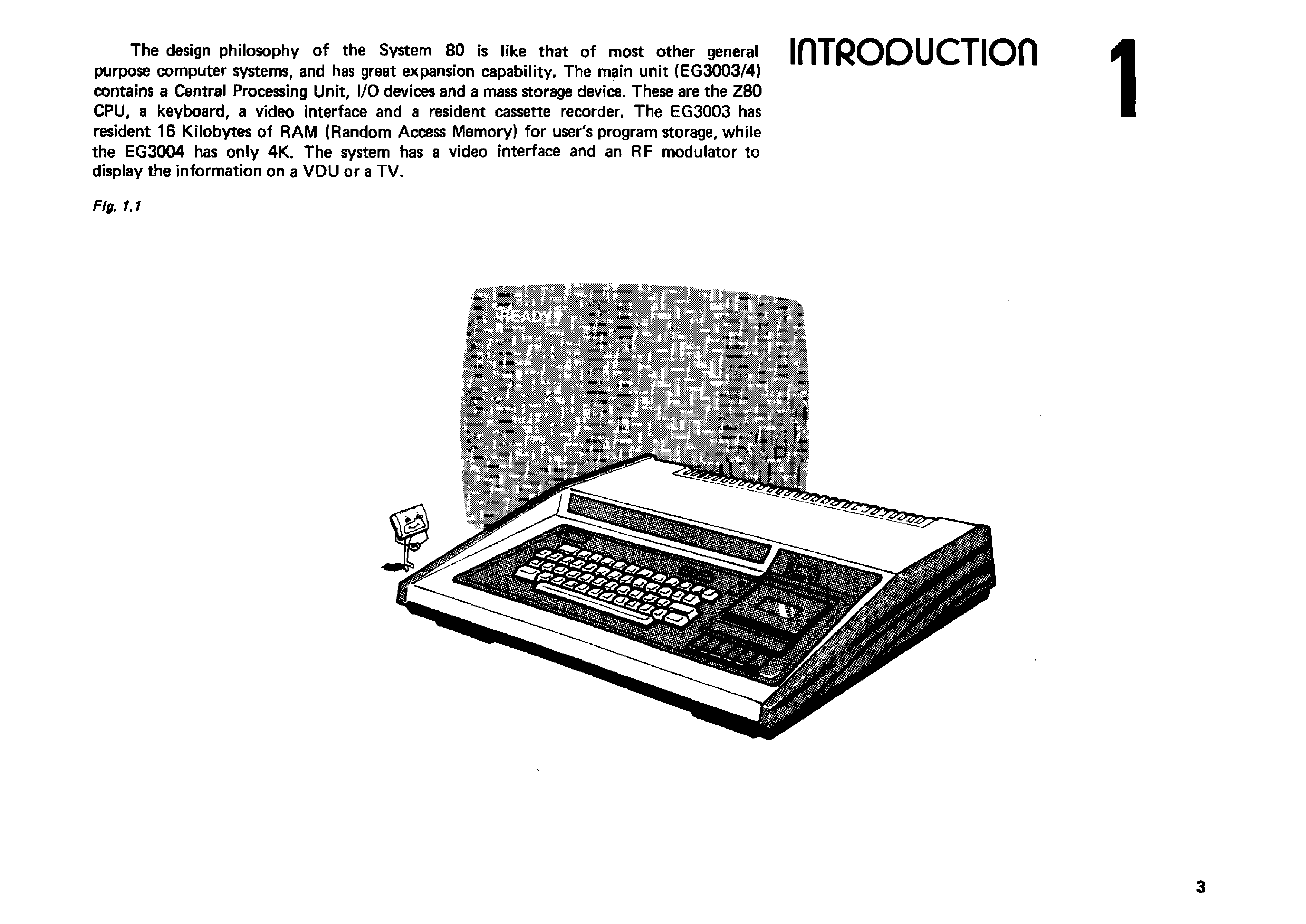
The design philosophy of the System 80 is like that of most other general
purpose computer systems, and has great expansion capability. The main unit (EG 3003/4)
contains a Central Processing Unit, I/O devices and a mass storage device. These are the Z80
CPU, a keyboard, a video interface and a resident cassette recorder. The EG3003 has
resident 16 Kilobytes of RAM (Random Access Memory) for user's program storage, while
the EG3004 has only 4K. The system has a video interface and an RF modulator to
display the information on a V D U or a T V .
IflTRODUCTIOn
Fig. 1.1

Beside the hardware configuration described, the System 80 has a powerful
resident EX TE N D E D BASIC Interpreter which is compatible with that o f TRS-80 Level II
BASIC.
An optional S-100 bus expansion box is designed to be connected to
the main unit. More peripherals can then be linked to the system by plugging their standard
interface cards into the S-100 bus mother-board. S-100 bus is now a standard in the micro
computer industry, especially for computers using 8080 or Z-80 CPUs.
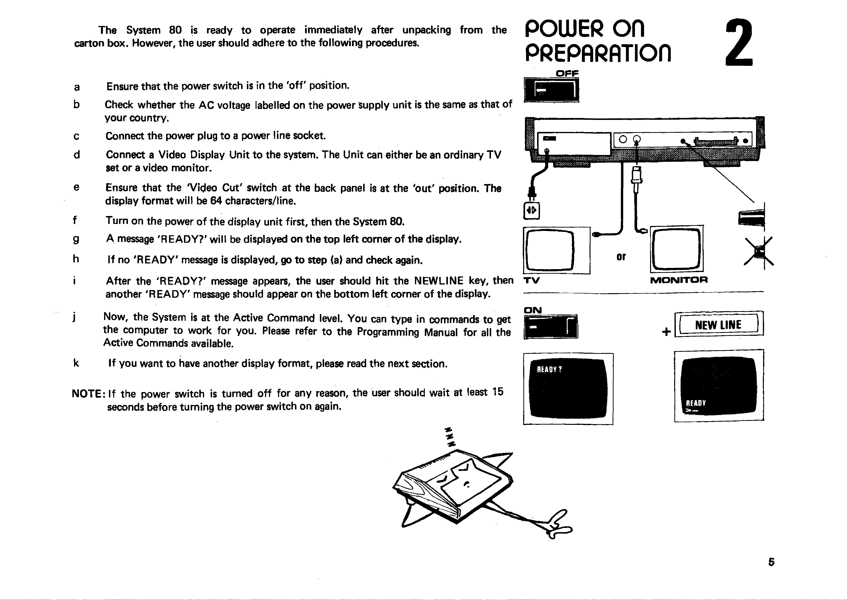
The System 80 is ready to operate immediately after unpacking from the
carton box. However, the user should adhere to the following procedures. POWER o n
PfiEPARflTIOn
a
b
c
d
e
f
g
h
i
Ensure that the power switch is in the 'o ff' position.
Check whether the AC voltage labelled on the power Supply unit is the same as that of
your country.
Connect the power plug to a power line socket.
Connect a Video Display Unit to the system. The Unit can either be an ordinary T V
set or a video monitor.
Ensure that the 'Video Cut' switch at the back panel is at the 'out' position. The
display format will be 64 characters/line.
Turn on the power of the display unit first, then the System 80.
A message 'REA DY?' will be displayed on the top left corner of the display.
If no 'R E A D Y ' message is displayed, go to step (a) and check again.
After the 'R EA D Y?' message appears, the user should hit the NEW LINE key, then
another 'R E A D Y ' message should appear on the bottom left corner of the display.
j Now, the System is at the Active Command level. You can type in commands to get
the computer to work for you. Please refer to the Programming Manual for all the
Active Commands available.
k If you want to have another display format, please read the next section.
NOTE: If the power switch is turned off for any reason, the user should wait at least 15
seconds before turning the power switch on again.
ON
H"UAOY ? 1
L
.
r NEW LINE
*
3.1 FO R M A T SELEC TIO N
The System 80 allows two kinds of display formats, that is, (1). 64 characters
per line; (2) 32 characters per line. The purpose of the latter is to permit an enlarged
and clear character display when a television set is used.
VIDEO Dl/PLAV
FORmflT
3.2 64 C H A R A C TE R S /L IN E FO RM AT
The 64 characters per line format is selected whenever the computer is turned on and
the V ID E O CUT button is off. The user may select 32 characters per line by pressing
the V ID E O CUT button.
VIDEO CUT
3.3 32 C H A R A C TE R S/LIN E FO R M AT I
a) Press the V ID E O CUT button on the back panel. H
b) Press the PAGE button on the front panel to read either the left half or the right ^
half of the text on the display.
;
....
^
6 4 characters
per line
32 characters
per Mne
3.4 SPACE IN SE R TIO N
A space can be inserted automatically between characters by typing in
PRIN T CHR $(23) This mode will be reset by NEW or CLS command.

The keyboard acts as a man-machine interface, while the cassette is used for mass
storage of programs and data.
4.1 Special Function Keys
PAGE — select page for display (refer to previous section).
FI — isolate the cassette from the control of the computer during winding and rewind
ing and allow manual cassette motor control.
BREAK — break a running program and return to the Active Command Level.
NEW LINE — enter a line o f command or data into the computer.
BACKSPACE — cancel the character previously typed.
ESC — the display echoes a [ sign which is an exponent sign used by the System.
CTL — move the cursor to the beginning of the next line.
S H IF T /C T L /I — tab function; move the cursor 8 spaces to the right.
S H IF T /C T L /Y — same as print CHR${23). See .section 3.4
SHIFT/BACKSPACE - delete line.
KEYBOARD &
CA//ETTE
4.2 Cassette Recorder
The cassette recorder is a high fidelity audio recorder. It has six piano keys*and a
3-digit counter. The keys function the same as those of a normal recorder. The user should
take the advantage o f the counter for fast program locating.
Program loading and saving will be discussed in detail in next section.
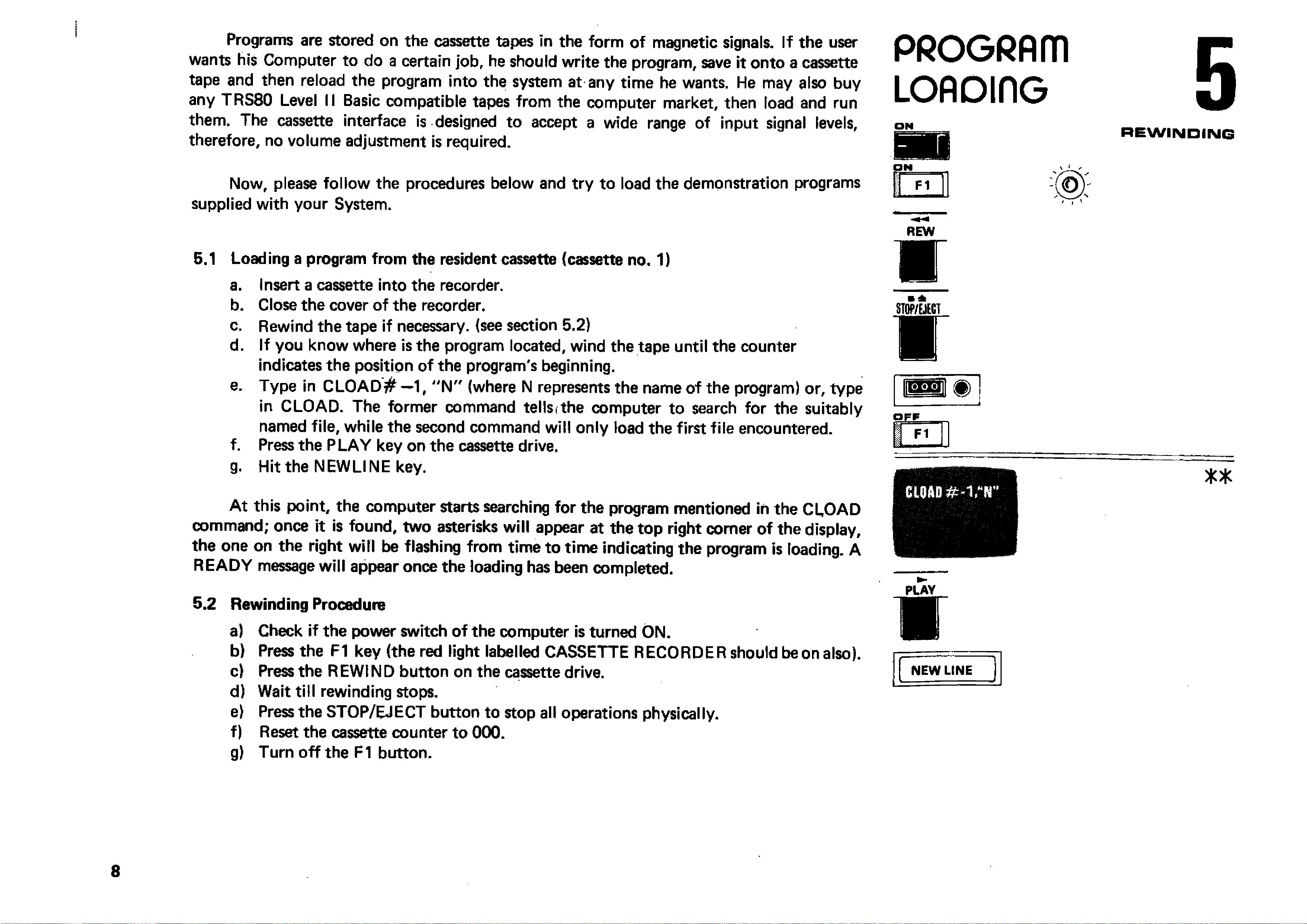
Programs are stored on the cassette tapes in the form of magnetic signals. If the user
wants his Computer to do a certain job, he should write the program, save it onto a cassette
tape and then reload the program into the system at any tim e he wants. He may also buy
any TRS80 Level II Basic compatible tapes from the computer market, then load and run
them. The cassette interface is designed to accept a wide range of input signal levels,
therefore, no volume adjustment is required.
Now, please follow the procedures below and try to load the demonstration programs
supplied with your System.
5.1 Loading a program from the resident cassette (cassette no. 1)
a. Insert a cassette into the recorder.
b. Close the cover of the recorder.
c. Rewind the tape if necessary, (see section 5.2)
d. If you know where is the program located, wind the tape until the counter
indicates the position of the program's beginning.
e. Type in C L O A D # —1, " N " (where N represents the name of the program) or, type
in CLOAD. The former command tellsfthe computer to search for the suitably
named file, while the second command will only load the first file encountered.
f. Press the PLAY key on the cassette drive.
g. Hit the NEW LINE key.
A t this point, the computer starts searching for the program mentioned in the CLOAD
command; once it is found, two asterisks will appear at the top right comer of the display,
the one on the right will be flashing from time to tim e indicating the program is loading. A
R EA D Y message will appear once the loading has been completed.
5.2 Rewinding Procedure
a) Check if the power switch of the computer is turned ON.
b) Press the F1 key (the red light labelled CASSETTE RECORDER should be on also).
c) Press the R EWIN D button on the cassette drive.
d) Wait till rewinding stops.
e) Press the STOP/EJECT button to stop all operations physically.
f) Reset the cassette counter to 000.
g) Turn o ff the F 1 button.
PROGRAIT1
L O A D in G
ON
REW
■
01P A D # - V r
5
REWINDING
* *
PLAY
V
I
I
r - - ■
NEW LINE
i
“

5.3 Checking a Program
a) Read the CLOAD command (section 1.5 in the BASIC Manual.)
b) Rewind the cassette tape to the starting point of the program.
c) Press the PLAY button on the cassette drive.
d) Type in the command CLOAD? from the keyboard.
e) Hit the NEW LINE key.
Once the computer finds the program, two asterisks will appear on the top right corner
of the display, the one on the right will be flashing if comparison is successful. A R E AD Y
message will appear if the comparison has been completed. Otherwise, the word BAD will be
displayed.
REW
s
PLAY
w
C10A0?
NEW LINE
'
----
-
■ ■
* *
o r
BAD
5.4 Listing and Executing a Program
a) Read the LIST and RUN commands (sections 1.9 and 1.11 in the BASIC
Manual).
b) Type in LIST and hit the NEW LIN E key (The entire program will be listed on the
display).
c) Type in RUN and hit the NEW LINE key (The computer starts executing the
program).
( n e w lin e ]
RUN
W A R N IN G : CASSETTE LO ADING
Although the cassette interface circuit can tolerate wide range of input signal level,
sometimes, loading error may occur. The reason is that so many software houses produce
TRS—80 compatible tapes and their quality may differ a lot. The only solution is to do a
backup fo r yourself and use the backup copy fo r future loading.
P
The backup procedure should be: —
(1) Put the TRS—80 compatible tape into second cassette.
(2) Connect the second cassette to the computer.
(3) Use CLOAD #—2, ‘F command to load the program into memory.
(4) Try to adjust the second cassette volume if loading fails.
(5) If the program is successfully loaded, save it onto a blank tape with cassette # 1.
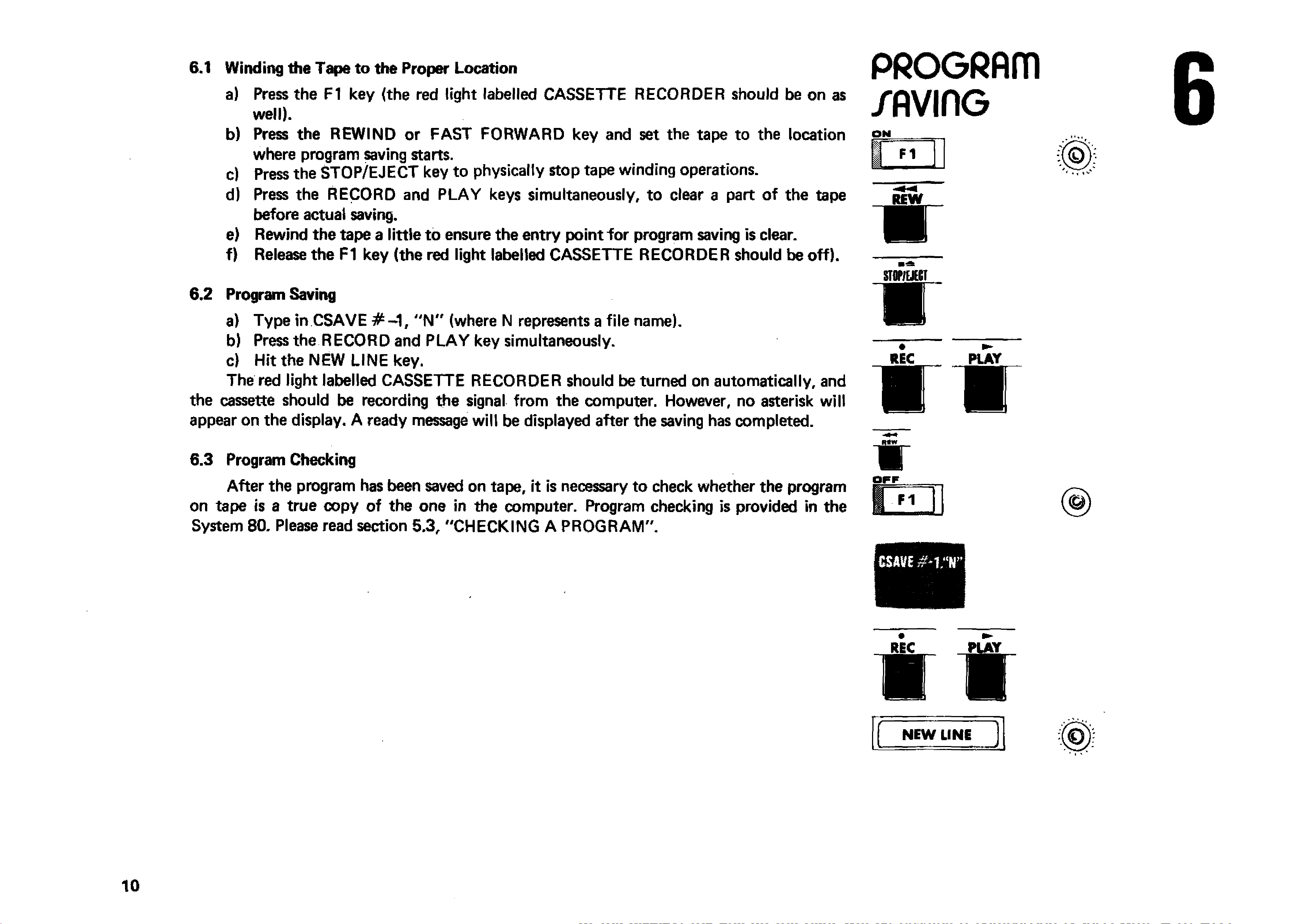
6.1 Winding the Tape to the Proper Location
a) Press the F1 key {the red light labelled CASSETTE RECORDER should be on as
well).
b) Press the REW IN D or FAST FORW ARD key and set the tape to the location
where program saving starts.
c) Press the STOP/EJECT key to physically stop tape winding operations.
d) Press the RECORD and PLAY keys simultaneously, to clear a part of the tape
before actual saving.
e) Rewind the tape a little to ensure the entry point to r program saving is clear.
f) Release the F1 key (the red light labelled CASSETTE RECORDER should be off).
6.2 Program Saving
a) Type in CSAVE # - 1 f "N " (where N represents a file name).
b) Press the RECORD and PLA Y key simultaneously.
c) Hit the NEW LINE key.
The red light labelled CASSETTE RECORDER should be turned on automatically, and
the cassette should be recording the signal from the computer. However, no asterisk will
appear on the display. A ready message will be displayed after the saving has completed.
6.3 Program Checking
After the program has been saved on tape, it is necessary to check whether the program
on tape is a true copy of the one in the computer. Program checking is provided in the
System 80. Please read section 5.3, "C HEC KING A PROG RAM ".
P R O G R A ITI
/ A V IflG
ON
STflPfEJECT
■
REC PLAY
i r
OFF
(&J
. V
REC PLAY
IV
f
NEW LINE )

Tw o cassette recorders are required in some applications such as payroll and account
ing. In these applications, old data have to be read into the computer sequentially from one
file and output to another file after processing or updating. The main unit already has the
interface for one more cassette recorder. Signal input/output is through the D IN jack at the
back panel. A cassette recorder cable is packed with the System.
Active Commands and instructions are provided to handle this extra cassette. These
a r e : —
(i) CLOAD -# -2, " M " — load a program called M from cassette '2'.
(ii) C S A V E # -2 , "M " — save a program onto cassette '2'.
(iii) P R IN T # -2 ,A ,B ,C $ —store the variables A, B and character string C$ onto cassette'2'.
(iv) IN P U T # -2 ,A ,B ,C $ — input the variables A, B and character string C$ from cassette'2 '
For further programming details, please refer to the BASIC Manual. The operating
procedure of the cassette '2 ' for playing (reading in data) or recording (outputting data onto
the tape) is same as that described in 4.1
Note: — The user may have to adjust output volume of his cassette until no error occurs
during cassette loading. The System 80 may have to be reset if invalid
data is read and causes a dead loop.
'Thafc~B my hearfe-beat;!!'
/Econo
CA//ETTE
RECORDER 7
S3
| | 9 oO * o |
WHITE TO MIC
BLUE TO REMOTE
BLACK TO EAR
m in VOLUME m a x
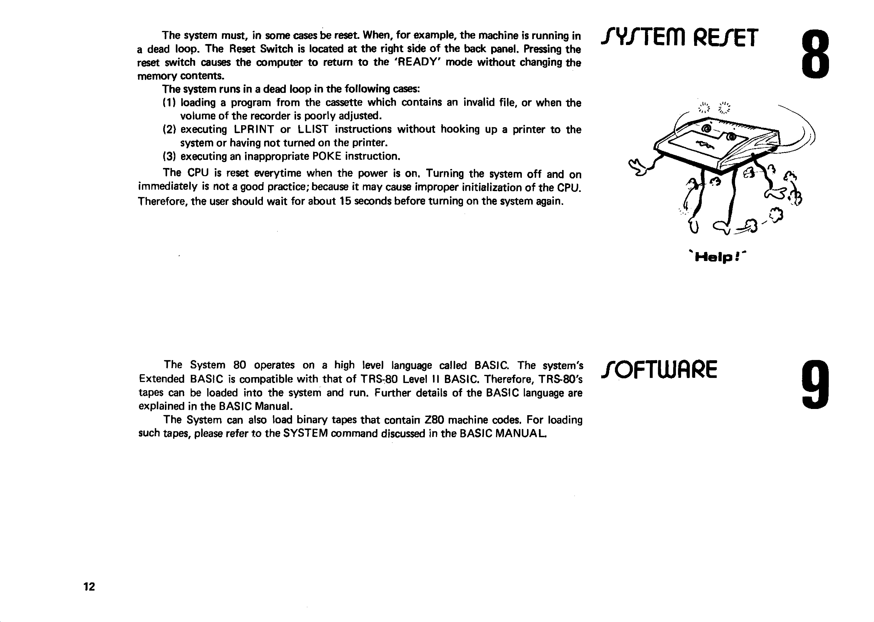
The system must, in some cases be reset. When, for example, the machine is running in
a dead loop. The Reset Switch is located at the right side o f the back panel. Pressing the
reset switch causes the computer to return to the 'R E A D Y ' mode w ithout changing the
memory contents.
The system runs in a dead loop in the following cases:
(1) loading a program from the cassette which contains an invalid file, or when the
volume of the recorder is poorly adjusted.
(2) executing LPR IN T or LLIST instructions without hooking up a printer to the
system or having not turned on the printer.
(3) executing an inappropriate POKE instruction.
The CPU is reset everytime when the power is on. Turning the system o ff and on
immediately is not a good practice; because it may cause improper initialization of the CPU.
Therefore, the user should wait for about 15 seconds before turning on the system again.
/Y/TEfTl RE/ET
Help
i
The System 80 operates on a high level language called BASIC. The system's
Extended BASIC is compatible with that of TRS-80 Level II BASIC. Therefore, TRS-80's
tapes can be loaded into the system and run. Further details of the BASIC language are
explained in the BASIC Manual.
The System can also load binary tapes that contain Z 80 machine codes. For loading
such tapes, please refer to the SYSTEM command discussed in the BASIC M A N U A L
/OFTWflRE

Cl I ELECTRICAL CHARACTERISTICS
POWER CONSUMPTION
CASSETTE IN PU T L E V E L
COMPUTER O U TP U T RECORDING LEVEL
APPEflDIK A
™ «“ *■> TECHdlCAL
1 V peak to peak /PECIFICflTIOfl/
0.3 V peak to peak
REMOTE SW ITCHING CA PACITY 0.5 A max at 6 V DC
V ID E O OUTPUT
C2J CONNECTORS PIN ASSIGNMENTS
2V peak to peak
(Negative sync pulse)
D IN JACK PIN CO NNECTIONS FOR A D D IT IO N A L CASSETTE
1 - REMOTE
2 - SIG N A L GRO UND
3 - REMOTE
4 - INPUT
5 - O UTPUT
DIN JACK PIN CO NNECTIONS FOR V ID E O IN TERFA C E
1 — +5 V
4 - V ID E O O UTPU T
5 - G ROUND
DIN JACK
VIEW ED FROM REAR SIDE OF THE SYSTEM. 1
2
EXPANSION PIN EDGE
VIEW ED FROM REAR SIDE 2
1
5 0
231
49
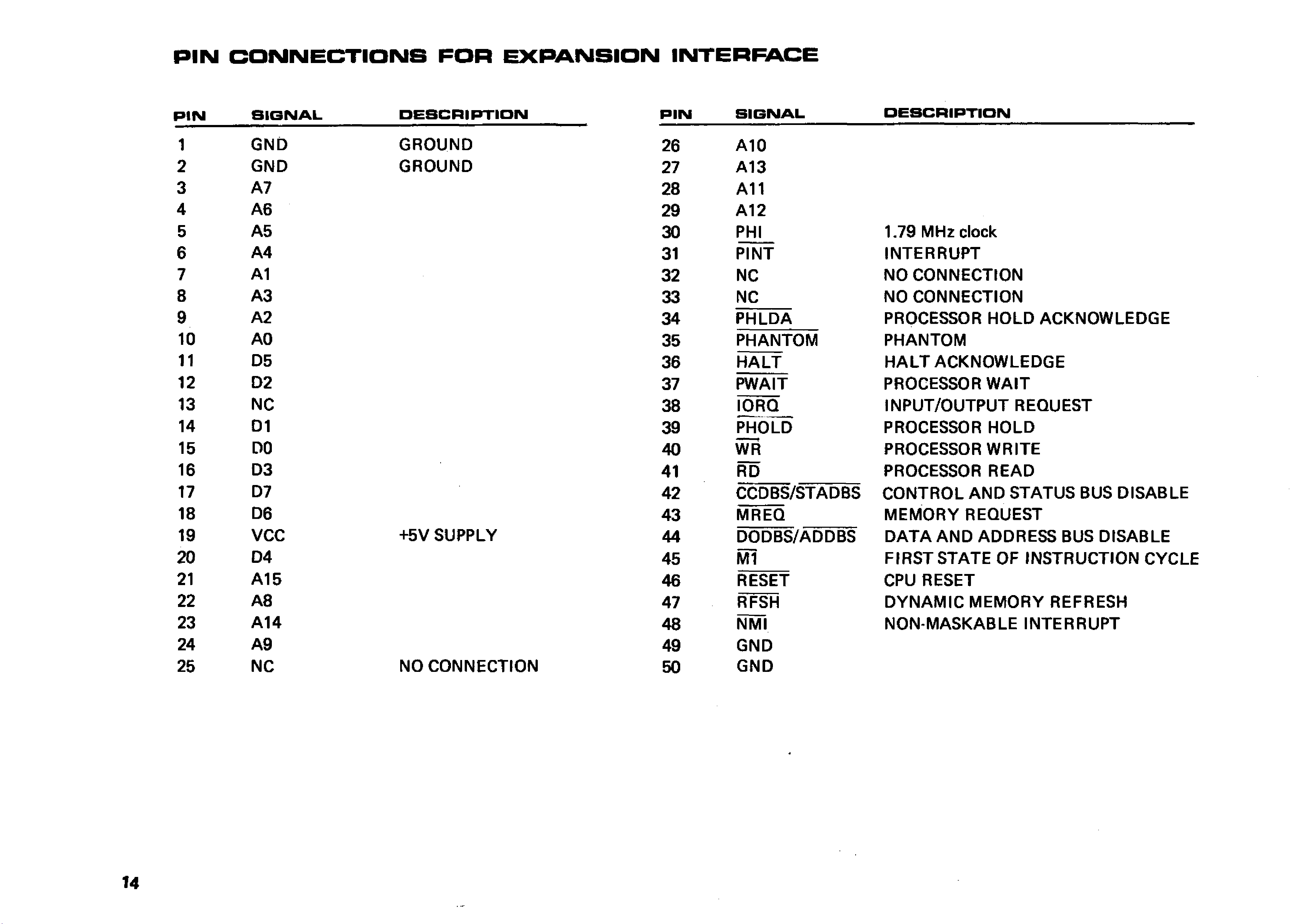
PIN CONNECTIONS FOR EXPANSION INTERFACE
PIN SIGNAL DESCRIPTION PIN SIGNAL DESCRIPTION
1GND GROUND 26 A 10
2GND GROUND 27 A13
3A7 28 A11
4A6 29 A12
5A5 30 PHI 1.79 MHz clock
6A4 31 PINT IN TE R R U P T
7A1 32 NC NO CONNECTIO N
8A 3 33 NC NO CO NNECTION
9A2 34 PHLDA PROCESSOR HO LD ACKNOW LEDGE
10 AO 35 PHANTOM PHANTOM
11 D5 36 H A LT H A LT ACKNOW LEDGE
12 D2 37 PW AIT PROCESSOR W A IT
13 NC 38 IORQ IN P U T/O U TP U T REQUEST
14 D1 39 PHOLD PROCESSOR HO LD
15 DO 40 WR PROCESSOR W R ITE
16 D3 41 RD PROCESSOR READ
17 D7 42 CCDBS/STADBS CO N TR O L A N D STATUS BUS DISABLE
18 D6 43 MREQ M EM O R Y REQUEST
19 VCC +5V SUPPLY 44 DODBS/ADDBS D A T A A N D ADDRESS BUS DISABLE
20 D4 45 M l FIR ST STATE OF IN STRUCTIO N CYCLE
21 A15 46 RESET CPU RESET
22 A8 47 RFSH D Y N A M IC M EM O R Y REFRESH
23 A 14 48 NMI NON-MASKABLE IN TERRU PT
24 A9 49 GND
25 NC NO CONNECTIO N 50 GND
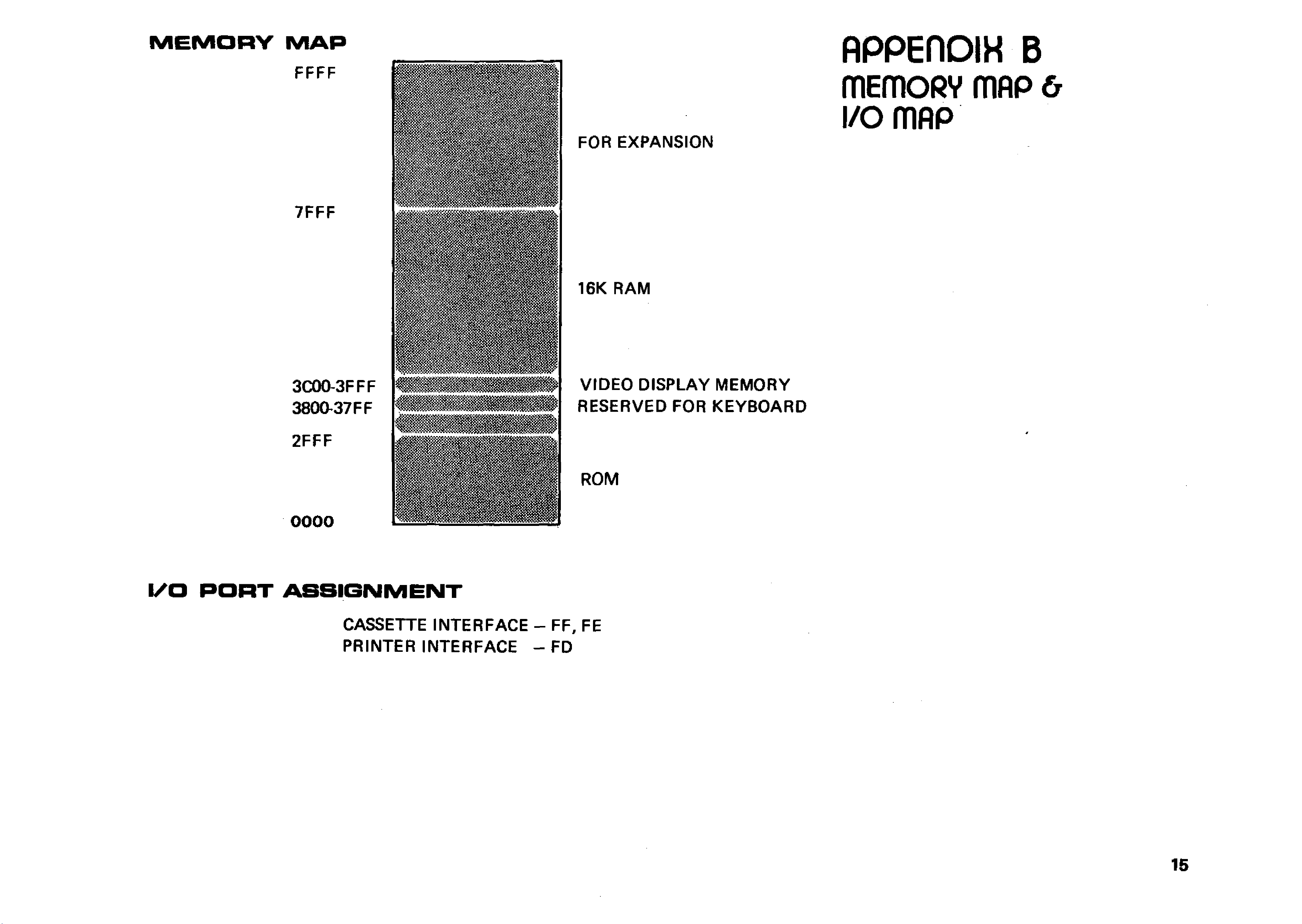
MEM ORY MAP
FOR EXPANSION
16K RAM
V ID E O D ISPLAY M EM O R Y
RESERVED FOR K EYBOARD
ROM
I/O PORT ASSIGNMENT
FFFF
7FFF
3C00-3FFF
3 8 0 0 3 7 FF
2FFF
00 OO
APPERDIH B
mEmoRV mflp &
i/o mop
CASSETTE IN TERFA C E - FF, FE
PR INTER IN TER FA CE - FD
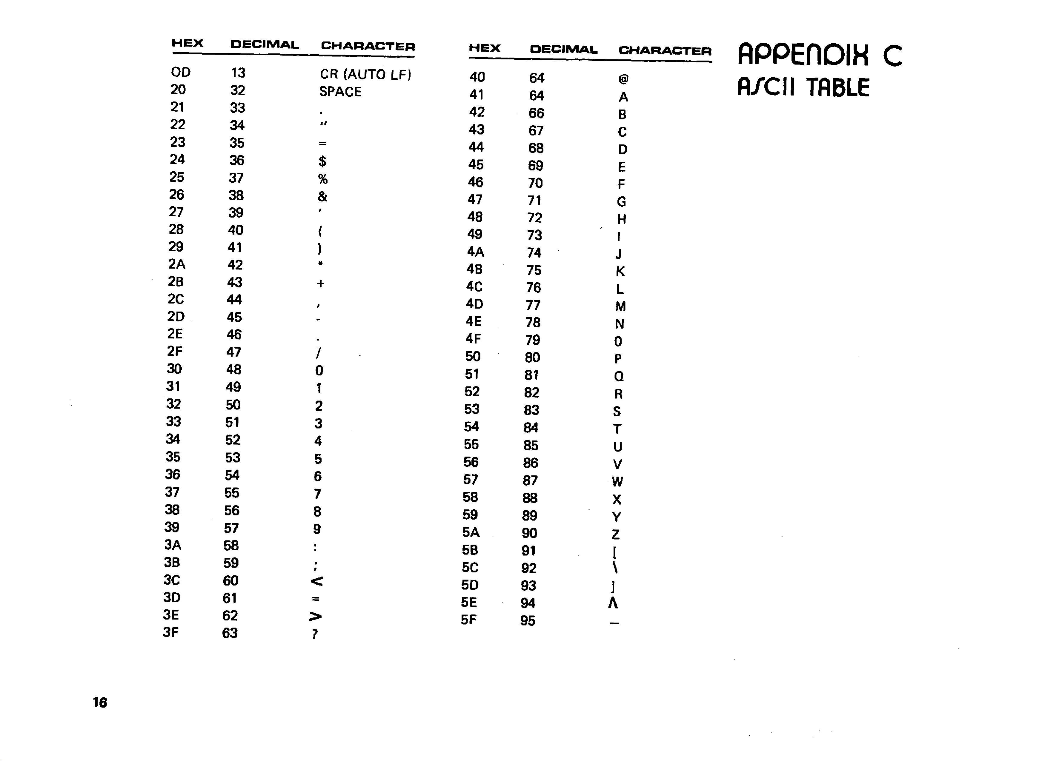
HEX DECIMAL CHARACTER HEX
OD 13 CR (AUTO LF) 40
20 32 SPACE 41
21 33 *42
22 34 u43
23 35 —44
24 36 $45
25 37 %46
26 38 &47
27 39 9
48
28 40 {49
29 41 )4A
2A 42 «4B
2B 43 +4C
2C 44 94D
2D 45 4E
2E 46
9
4F
2F 47 /50
30 48 051
31 49 152
32 50 253
33 51 354
34 52 455
35 53 556
36 54 657
37 55 758
38 56 859
39 57 95A
3A 58 •
•5B
3B 59 >
f5C
3C 60 <5D
3D 61 =5E
3E 62 >5F
3F 63 ?
DECIMAL CHARACTER
APPEflDIH C
fl/C II TABLE
64 @
64 A
66 B
67 C
68 D
69 E
70 F
71 G
72 H
73
*
I
74 J
75 K
76 L
77 M
78 N
79 0
80 P
81 Q
82 R
83 S
84 T
85 U
86 V
87 w
88 X
89 Y
90 z
91 [
92 \
93 ]
94 A
95 _ _
M A N U A L
(Attach to System 8 0 user's m an u al)
Introduction
T h is is an enhanced version of System 8 0 . An 1.5K ROM is added to provide new keyboard and display
functions, statement renumber command, and a machine language monitor.
New keyboard and display functions, and the m onitor w ill be discussed in the following pages. The Renumber command is
described in the Active Command section of the BASIC manual. For power up procedure, cassette operations and other system
features, please refer to the old user's manual.
Enable the 1.5K ROM routines
The computer is fitted w ith an exclusive 1.5K extension to the Microsoft 12K BASIC, featuring upper and lower case,
flashing cursor, auto repeat keyboard, screen print, machine language m onitor, and renumber functions.
To use these functions, the BASIC extension should be initialised immediately after the machine entering BASIC Active
Command level;
The initialisation procedure is
i) type SYSTEMINEWLINB
ii) reply *?
iii) ty p e /12288 [N EW LIN El
iv) A flashing cursor will show on the screen.
The entry address 12288 used in step (iii) w ill enable all the ROM facilities. If you just want part of them, there are tw o other
choices. Enter address 12299 w ill retain all the facilities except flashing cursor. Enter address 12294 will have lower case fa cility
only.
New Keyboard functions
Input lower case characters
Lower case characters can be input by hitting the character key w ith the SHIFT key
depressed.
Repeat Key
A fte r pressing a key longer than one second, the computer automatically repeats entering
that character until the key is released.
Print Screen
By h ittin g SHIFT —[ 0 — P, the computer w ill transfer the inform ation displayed on the
screen to the printer. If no printer is connected or the printer is turned off, the computer
w ill skip the printing process instead of locking up itself in waiting. Once the SCREEN
PRINT function is activated, both alphanumeric and graphic characters on the screen Will
transfer to the printer. Only thctee printers that can recognise System 80 or TRS-80 graphic
characters are able to print the graphics. Otherwise, only alphanumeric characters can be
printed.
Disabled flashing cursor
A flashing cursor can attract the operations attention, however, somebody may feel it
frustrating.
In order to disable the flashing cursor, hit SHIFT-BREAK. To enable it, hit
SHIFT-BREAK again. If you d on't want a flashing cursor at the start, please enter 12299
instead o f 12288 during ROM initialization.
Other manuals for System 80
2
Table of contents
Other Dick Smith Desktop manuals


