Dick Smith DSLED42UHDYA User manual


-3-
SAFETY AND WARNINGS
IMPORTANT SAFETY INSTRUCTIONS
1) Read these instructions.
2) Keep these instructions.
3) Heed all warnings.
4) Follow all instructions.
5) Do not use this apparatus near water.
6) Clean only with a dry cloth.
7) Do not block any ventilation openings, install in
accordance with the instructions.
8) Do not install near any heat sources such as
radiators, air conditioners, stoves, or other
apparatus (including amplifiers) that produce heat.
9) Protect the power cord from being walked on or
pinched particularly at plugs, convenience
receptacles, and the point where they exit from the
apparatus.
10) Only use attachments/accessories specified by
the manufacturer.
11) Unplug this apparatus before the approach of
lightning storms or when unused for long periods of
time.
12) Refer all servicing to qualified service
personnel. Servicing is required when the
apparatus has been damaged in any way, such as
when the power-supply cord or plug is damaged,
liquid has been spilled or objects have fallen into
the apparatus, the apparatus has been exposed to
rain or moisture, does not operate normally, or has
been dropped.
13) The Mains plug is used as the power disconnect
device, and the disconnect device shall remain
readily accessible and operable.
14) The ventilation should not be impeded by
covering the ventilation openings with items such as
newspapers, table-cloth, curtains, etc.
15) No naked flame sources, such as lighted
candles, should be placed on or near the apparatus.
16) This device is not warranted for use in
unreasonably hot, cold, or humid environments.
17) The apparatus shall not be exposed to dripping
or splashing and no objects filled with liquids, such
as vases, shall be placed on or near the apparatus.
18) This device is designed for indoor, fixed location
use only. It must not be used in portable or mobile
applications as vibration or excessive forces may
damage the unit.
RISK OF ELECTRIC SHOCK
DO NOT OPEN!
CAUTION
CAUTION
This symbol indicates that dangerous voltages,
constituting a risk of electric shock are present
within this unit.
This symbol indicates that there are important
operating and maintenance instructions in the
literature accompanying this unit.
To reduce the risk of fire or electric shock, do
not expose this apparatus to rain or moisture.
WARNING:
This symbol indicates that this product
incorporates double insulation between hazardous
mains voltage and user accessible parts. When
servicing use only identical replacement parts.
The batteries shall not be exposed to excessive
heat such as sunshine, fire or the like.
WARNING:
TO REDUCE THE RISK OF ELECTRIC
SHOCK, DO NOT REMOVE COVER (OR
BACK). NO USER SERVICEABLE PARTS
INSIDE. REFER SERVICING TO QUALIFIED
SERVICE PERSONNEL.
HDMI,the HDMI logo,and High-Definition Multimedia
Interface are trademarks or registered trademarks of
HDMI Licensing LLC in the United States and other
countries.
-4-
High voltages are used in the operation of this
television receiver. Do not remove the cabinet
back from your set.
Refer servicing to qualified service personnel.
To prevent fire or electrical shock hazard, do not
expose the television receiver to rain or moisture.
Do not drop or push objects into the television
cabinet slots or openings. Never spill any kind
of liquid on the television receiver.
Do not block the ventilation holes in the back
cover.
Adequate ventilation is essential to prevent
failure of electrical components.
Do not trap the power supply cord under the
television receiver.
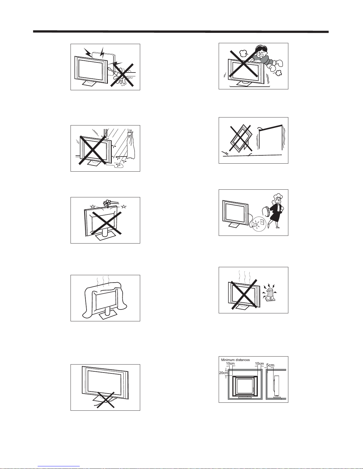
Never stand on, lean on, or suddenly push the
television or its stand. You should pay special
attention to children. Serious injury may result if it
falls.
Do not place your television on an unstable cart,
stand, shelf or table. Serious injury to an individual,
and damage to the television may result if it falls.
When the television receiver is not used for an
extended period of time, it is advisable to
disconnect the AC power cord from the AC outlet.
Avoid exposing the television receiver to direct sunlight
and other sources of heat. Do not stand the television
receiver directly on other products which give off heat,
e.g. video cassette players and audio amplifiers. Do not
place naked flame sources, such as lighted candles on
or near the television.
If the television is to be built into a compartment or similar
enclosure, the minimum distances must be maintained. Heat
build-up can reduce the service life of your television, and
can also be dangerous.
Dim: 515*3 20mm(不 包括底 座)
SAFETY AND WARNINGS

-5-
SAFETY AND WARNINGS
CAUTION
Never tamper with any components inside the TV, or any other adjustment controls not mentioned in this manual.
All LCD-TVs are high voltage instruments. When you clean up dust or water drops on the LCD PANEL or CABINET,
the power cord should be physically removed from the mains outlet. You may then wipe the TV with a dry soft cloth.
Before thunder and lightning storm events arrive, unplug the power cord and antenna cord to minimise the risk of
damage to your TV.
a. Do not expose to dripping or splashing.
b. No objects filled with liquids, such as vases, shall be placed on or near the apparatus.
c. is used as the power disconnect device and shall remain readily accessible and
operable.
d. No naked flame sources, such as lighted candles, should be placed on or near the apparatus.
e. Allow suitable distances around the apparatus for sufficient ventilation. Ventilation should not be impeded by
covering ventilation openings with items such as newspapers, table cloths, curtains and such like.
f. Do not expose to vibration or shock.
The mains plug of this device
The display panel is a very sensitive high technology product, giving you finely detailed pictures. Occasionally, a
few non-active pixels may appear on the screen as a fixed point of black, blue, green or red. Please note that
this does not affect the performance of your product.
About After- Image:
The extended use of fixed image programme material can cause a permanent after - image on the screen. This
background image is viewable on normal programs in the form of a stationary fixed image. This type of
irreversible screen deterioration can be limited by:
A. Reduce the brightness/contrast setting to a minimum viewing level.
B. Do not display any fixed image for extended periods of time.
C. Turn the power off when not in actual use.
Important Information Regarding Use of Video Games, Computers, Captions or Other Fixed Image Displays.
Do not allow a still picture to be displayed for an extended period, as this can cause a permanent after-image to
remain on the screen.
Examples of still pictures include logos, video games, computer images, teletext and images displayed in 4:3
mode.
CAUTION:
The permanent after-image on the screen resulting from fixed image use is not an operating defect. This product
is not designed to display fixed images for extended periods of time.
WARNING: All repairs to this TV must only be performed by qualified TV service personnel. There are
no user-serviceable components within this equipment. Changes or modifications to this unit, including
changes to parts, components and constructional attributes that are responsible for safety and
regulatory compliance, may result in non-compliant and unsafe operation of this equipment.

-6-
Base Stand Assembly Instructions
Prepare to place the TV with the display side down onto a flat surface. Due to the size and weight of
this TV, the use of 2 people is recommended when moving it. Ensure the table or desk you use provides
a flat, totally clean surface, and use a soft cloth between the face of the TV and the table to help protect
the TV's screen.
Thank you for purchasing this Dick Smith 41.5" UHD LED LCD TV. Before connection and operation of this
product, please read through this User Manual carefully, and retain the manual for future reference.
Remove the TV carefully from its packaging, taking care not to apply any pressure to the front of the LCD
screen. Some accessory items may be located in cut-out sections of the internal packaging, so take care not
to miss these items. Once all items are removed from the packaging, use the list below to check that nothing
is missing. If any items appear to be missing, contact the retail store that supplied the TV, or use the Support
contact details at the end of this manual for further information.
● 41.5" (105.5cm) LED LCD TV 1 piece
● Desk base stand 1 piece
● Neck brackets (links TV body & base stand) 2 pieces
● User Manual 1 piece
● Remote Control 1 piece
● Pack of screws (4 x short, 4 x long) 1 piece
● Pack of 2 "AAA" size batteries 1 piece
● Pack of 4 M6 wall-mount screws 1 piece
Once all the accessory items have been accounted for, prepare a location where you can attach the desk base
stand to the body of the TV. You will need to arrange a soft cloth that is large enough to cover the front face of
the TV (for protection of the LCD screen), as well as a Philips head screwdriver to attach the base stand.
Before proceeding to the Getting Started section of this manual, please continue reviewing this Installation
chapter to ensure that your TV is correctly connected to your TV antenna and related AV equipment (eg. DVD
or Blu-ray player, amplifier, sound bar etc).
Unpacking and preparing the TV
INSTALLATION
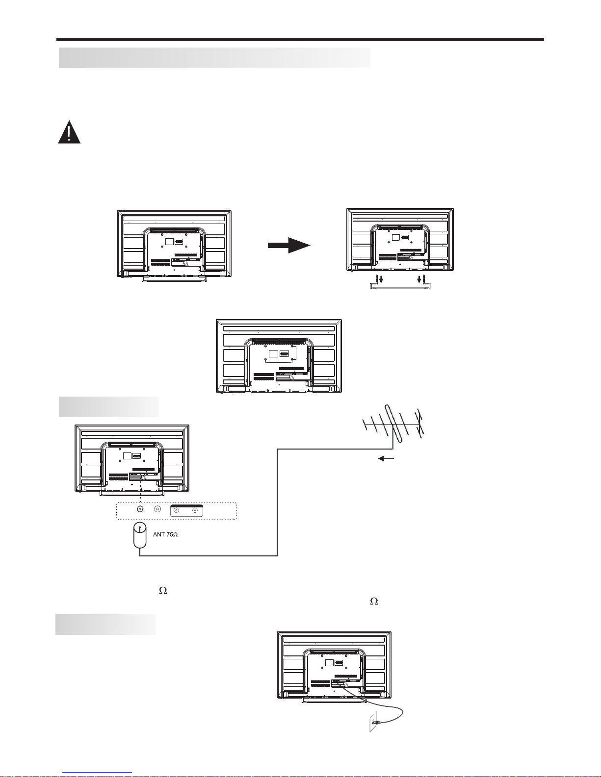
1) Position the base stand on a flat surface in front of you as per Fig 1 below. The rubber feet on the front
section of the stand should be facing downwards towards the surface the stand is sitting on.
2) Locate the right-angled Neck bracket with the L (Left) symbol on the top of the flat surface near the
screw holes, and screw it to the left side of the base stand using 2 of the supplied short Philips-head
screws. Repeat the process for the Neck bracket with the R (Right) symbol on it.
3) Position the TV's body on your desk or table so that the bottom of the TV is extending slightly over the
edge of the table when viewed for above. Position the assembled base stand as per Fig 2 below (with the
front section of the stand pointing away from you when viewed from above the rear of the TV).
4) Slide the ends of the neck brackets from the base stand into the rectangular holes in the bottom area
of the TV's body, and when correctly located, slowly and evenly push them into the body of the TV until
they are seated into position.
5) Secure the neck brackets in place using the longer Philips-head screws, as per Fig 3.
Neck bracket
(Left)
Neck bracket
(Right)
TV Stand Base Front
Fig 1. Fig 2. Fig 3.
INSTALLATION
WALL MOUNTING INSTALLATION GUIDELINES
For wall mounting with an optional bracket, please read the following instructions in conjunction with the
bracket's instructions. Make sure qualified service personnel perform the operation.
This television can be wall mounted as follows:
1. Place the LED LCD Television face down onto a solid surface. Please place some soft c l ot h material
over the front of the screen to help protect it from any damage. The LCD panel is a fragile component,
and must be suitably protected when removing the base stand. Be sure that no hard or sharp objects can
come into contact with the screen's surface. Do not exert pressure on the front of the unit at any time, as
this may damage the LCD screen.
2. Remove the 4 long screws from the lower part of the television, where the neck brackets from the desk
stand are attached to the TV’s body, and take away the stand (put the stand and screws somewhere
safe for future use).
3. Use the four M6 screws provided with your TV to fix it onto your wall mounting bracket (not included)
via the four VESA standard holes on the back of the television.
-7-
200mm x 100mm VESA
wall mounting hole spacing
and locations
POWER
AC Input
100-240V~ 50/60Hz 80W
N.B. Unwind the mains power cord
to its full length prior to initial use,
and locate it away from other cables
that will be connected to the TV
ANTENNA
Note:
Aerial connections: IEC (PAL-type, female).
Input impedance: 75 unbalanced.
For optimum digital TV reception, the use of high quality shielded 75 coax cable is recommended.
Plug (not supplied)
Outdoor antenna (not supplied)
N.B. - Take care to only connect your antenna to
the RF socket on the TV.
Other sockets may accept the PAL antenna plug,
but no reception will occur.
R F L R
Coaxi al
AUDIO O UTPUT
100
200
INSTALLATION
-8-
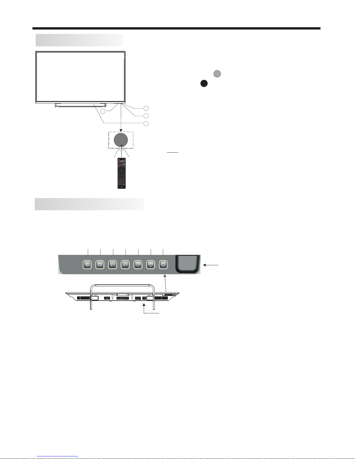
FRONT PANEL layout
KEYBOARD layout (side-panel)
1. SOURCE:
Displays the input source Menu.
2.MENU:
Displays the main MENU.
3.V-/V+
Adjusts the sound level.
In MENU mode, press "V+" or "V-" to adjust the item that you have selected.
4.CH-/CH+
In TV mode, press "CH+" or "CH-" to change the channel up or down.
In MENU mode, press "CH+" or "CH-" to select items.
5. STANDBY
Once the TV's main power switch has been activated, press this button to turn the
unit ON from STANDBY mode. Press it again to return the set back to STANDBY. This
Standby button performs the same operation as the Power/Standby button on the Remote
Control.
1: Remote control sensor.
2: Power indicator LED:
GREEN = POWER ON.
RED = Stand-by.
3: Keyboard (on bottom of TV).
4: Main power switch (on bottom mid
right-hand panel of TV)
This TV is most easily operated using the supplied Remote Control unit, but in the event
that the Remote is not available, there are various alternative controls for basic functions
located on the bottom of the TV (when viewed from the front of the TV).
30 3 0
3
1
2
4
SOURCE MENU V- V+ CH- CH+ Standby
(Input selection) (Power ON/Stand-by select)
(Bottom view of TV)
The remote control needs to be pointed directly,
within +/- 30° of the sensor on the front of the TV
for reliable operation.
NB. There will be a 5-10 second delay between
the power indicator LED changing colour and the
TV responding. If you also have other accessories
attached (eg. such as larger USB hard-drives) the
power-up sequence will take longer.
Remote Control sensor
Main power switch

INSTALLATION
-9-
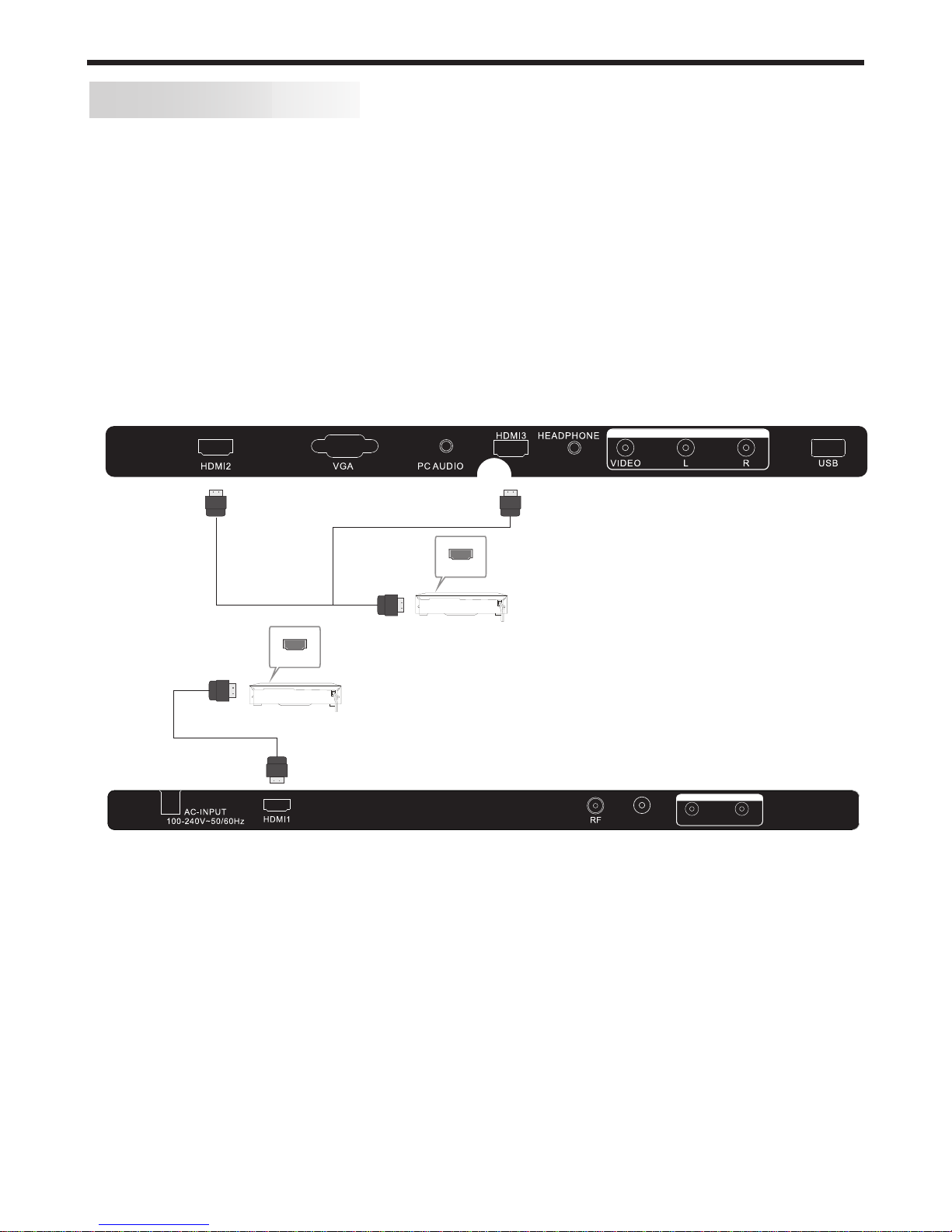
REAR AV Connections
SIDE AV Connections
When viewed from the rear of the TV, the following terminals/connections are visible (from left
to right):
● AC mains power cord
● HDMI 1 input (HDMI v2.0 socket for UHD source material)
● RF (TV Antenna) Input
● Coaxial digital Audio Output (RCA socket)
● AUDIO OUTPUT sockets - RCA type sockets for Left and Right audio outputs.
Note: These input and output sockets provide different functionality based on what mode the
TV is in.
- During DTV and ATV reception, USB playback, and HDMI or AV input operation, the
AUDIO OUTPUT sockets provide Audio outputs.
- Some settings on the TV (eg. the Mute control, Sound Menu settings etc) do not affect the
audio signal from the AUDIO OUTPUT socket.
- Only HDMI 1 input supports UHD source material.
- Only HDMI 1 input supports limited ARC (Audio Return Channel) functionality and you
must use an HDMI cable that supports ARC and CEC operation.
- All HDMI inputs support limited CEC (Consumer Electronics Control) functionality.
- The Coaxial digital Audio socket provides an output during DTV, USB playback and HDMI
input operation. The format of the digital output is set in the main Sound Menu (refer to
page 19 for details on setting the output format).
When viewed from the side of the TV, the following connections are visible (from left to right):
●
● VGA Input (analogue, 15 pin D-type socket)
● PC Audio Input
● HDMI 3 Input (1080p max resolution source material)
● Headphone Output (3.5mm stereo socket)
● AV INPUT sockets - RCA type socket for Composite type VIDEO input, and RCA type sockets
for Left and Right audio inputs.
● USB socket for HDTV record/playback
Note: When an HDMI port detects a DVI format signal, the matching audio signal is received
through the PC Audio input socket.
- Don't connect both an HDMI and an AV cable to the same device (eg. Blu-ray player),
as this TV may detect the duplication and report an error.
- Use only USB flash-drives or low-power portable USB hard-drives for HDTV recording.
- During AV mode operation, the AV INPUT sockets will disregard the audio inputs unless
they are accompanied by a composite Video input signal.
HDMI 2 Input (1080p max resolution source material)
AV INPUT
L R
AUDIO OUTPUT
Coaxial
(UHD input)
INSTALLATION
-10-
AV EQUIPMENT connections
You can use the input and output terminals on the TV set as follows for basic accessory
inter-connections.
a) HDMI (basic)
HDMI is a digital connection system that can carry both video and audio information. Using
HDMI connections to this TV is recommended where accessory equipment can support
higher resolution modes (such as 1080i/1080p) from products such as upscaling DVD
players, Blu-ray players and high-performance gaming consoles. For access to UHD
resolution material, such as from upscaling Blu-ray players, use only HDMI 1 input.
For basic HDMI installations, where an external surround sound processor/amplifier is not
being used, connect your accessory equipment directly to the HDMI sockets on this TV
using high quality HDMI certified cabling that supports ARC and CEC operation. All the
HDMI inputs support limited HDMI CEC (Consumer Electronics Control) functionality (refer
to page 20 for further details on CEC operation).
b) HDMI (advanced)
When using a Surround/AV amplifier system, there are numerous connection possibilities,
depending on the capabilities of the amplifier equipment. In most cases, external
accessories (such as a Blu-ray player or gaming console) that were previously connected
directly to the TV would now be connected to the amplifier via HDMI, and a seperate HDMI
cable would then be connected between the TV and the AV amplifier.
This system then allows the Surround/AV amplifier to process the surround channels and
correctly align the video and audio timing. If your Surround/AV amplifier supports HDMI
ARC (Audio Return Channel), then the HDMI ARC compliant cable connecting the amplifier
and TV together must be connected to the HDMI 1 input on this TV, otherwise a separate
audio connection (either analogue or coaxial digital) would also be required between the TV
and the AV amplifier. Refer to the User Manual for your AV amplifier for details on its specific
cabling requirements. Due to technical differences between equipment manufacturers,
HDMI ARC operation may not be possible in some installations.
HD MI
HD MI
NB. Only one HDMI input can be
selected at a time.
VIDEO EQUIPMENT with HDMI output
VIDEO EQUIPMENT with HDMI output
HDMI 1 input supports limited ARC (Audio Return Channel).
All HDMI inputs support limited CEC (Consumer Electronics
Control) operation.
AV INPUT
L R
AUDIO OUTPUT
Coaxial
(UHD input)
HDMI 1 input supports UHD resolution source material
(up to 3840 x 2160p).

INSTALLATION
-11-
d) AUDIO
For installations where you have an existing stereo system and wish to improve your
listening experience, connect a stereo RCA cable between the AV Output L/R sockets on
this TV and the appropriate line-level inputs (eg. AUX input) on your amplifier.
For even higher quality audio signal transfer to a Sound Bar or home theatre system that
supports digital audio inputs, consider using the Coaxial Digital audio output on the TV's
side panel. Use a well shielded coax cable with RCA connectors to connect the TV to your
compatible sound equipment, and then adjust the SPDIF Mode setting in the main Sound
Menu to "PCM" if required.
NB. Take care when powering up your TV/amp combination, as there may be some click or
pop sounds on the audio output of the TV during its powering up/down phase that can be
amplified by your sound system. It is highly recommended that the TV is first powered up,
and then when its screen is active, you then power up your amplifier. When powering down
the TV/amp system, turn Off your amplifier first and then switch the TV back to its Standby
state.
c) AV (Audio/Video)
This TV provides an AV input and AUDIO output using line-level analogue stereo Audio and
composite format Video signals for compatibility with earlier accessory devices eg. VCRs,
CRT TVs, basic gaming consoles etc. Refer to page 9 regarding the specific characteristics
of these AV sockets. For optimum composite video quality, use only well shielded 75 ohm
video-grade cables.
Yellow (Composite video)
White (Audio Left)
Red (Audio Right)
Y
W
R
VIDEO EQUIPMENT
VIDEO EQUIPMENT (Composite video output)
W
R
W R
TO AUDIO OUTPUTS
TO VIDEO
OUTPUTS
Y
Y
AV INPUT
AUDIO AMPLIFIER (analogue input)
W
R
W R
TO AUDIO INPUTS
White (Audio Left)
Red (Audio Right)
W
R
L R
AUDIO OUTPUT
Coaxial
(UHD input)

-12-
INSTALLATION
PC Connections
PRESET MODE
1
2
3
4
5
6
7
720*400
640*480
800*600
800*600
800*600
1024*768
1024*768
70
60
56
60
72
60
70
31.47
31.47
35.156
37.88
48.08
48.36
56.48
RESOLUTION V.Freq.(Hz) H.Freq.(kHz)
STEPS:
Be sure both the TV and computer are set to
Power off.
1.Connect a VGA and audio cable.
2.Connect the power cord.
3.Power on the TV, switch to PC mode.
4.Power on the PC.
This connection and power-up sequence is very
important. Also, for higher resolution
applications, the use of a high quality shielded
VGA cable is recommended.
The above resolutions are the only ones guaranteed to be supported. Other resolutions may also be
supported, but this must be assessed by the user on a case-by-case basis. This is also subject to the
limitiations of the computer’s video card.
ADJUSTABLE MODES
While this TV may support higher resolutions thru either the VGA or HDMI inputs, such operation is dependant on
the capabilities of the attached PC (including its graphics card, system set-up and operating system) as well as the
user’s ability to adjust the PC’s settings for optimum screen performance. Some PC graphics cards will not
correctly identify the TV’s capabilities and hence will only allow lower resolution screen displays.
This TV provides an analogue VGA input (15pin) for connection to various desktop or laptop computers. Refer to
your computer’s User manual or support website to determine if your computer may be compatible, and what
connection cabling will be needed.
VGA and audio cable
not supplied
AV INPUT
-13-
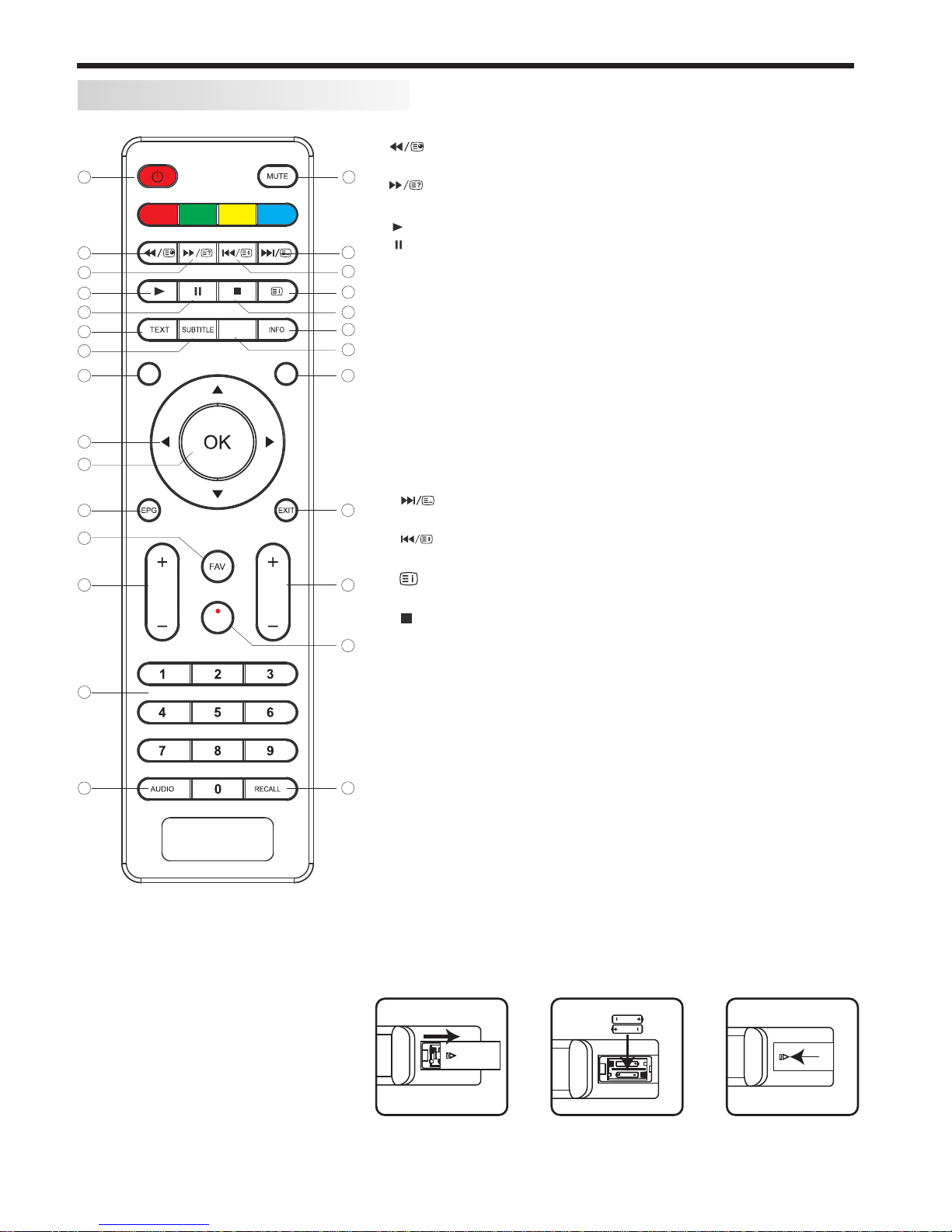
REMOTE CONTROL
REMOTE CONTROL
1:POWER: To set the TV to Standby or Power On modes.
2: :In USB mode, used as fast reverse key; press repeatedly to
speed up operation.
3: : In USB mode, used as fast forward key; press repeatedly to
speed up operation.
4: : Press the Play Button in USB mode to begin or continue Playback.
5: : Press the Pause Button to pause play in USB mode.
6:TEXT:To enter or exit TELETEXT.
7: SUBTITLE: To turn on subtitles in DTV mode.
8 :MENU: Displays the main on-screen menus.
9 :CURSOR: To move within the menu.
10:OK: Confirms selection.
11:EPG: To display information about the program being viewed
and what's on next in DTV mode.
12:FAV: To access your favourite channels list in TV or DTV mode.
13:VOL+/- : To adjust sound level.
14:NUMERIC KEY: For direct access to channels.
15:AUDIO: To select the available audio language of TV programs .
16:MUTE: To disable or enable the speaker sound output.
17: : In USB mode, used as next key, in teletext mode used as
list key.
18: : In USB mode, used as previous key, in teletext mode used
as hold key.
19: : In teletext mode used as index. In DTV mode, displays the
Recorded List.
20: : Press to stop play in USB mode.
21:INFO: To display the program information of the DTV show you
are watching, press the Info button.
22:FREEZE: Press to freeze the picture you are watching.
23:INPUT: Press to display and select the available video input sources.
24:EXIT: To return to the previous menu or exit menu.
25:CH+/CH-: To access the next or previous channels.
26:REC: Press to record the TV program you are watching in
DTV mode
27:RECALL: DTV Mode: RECALL: Jumps to last channel viewed.
1
2
3
4
5
6
7
8
9
10
11
13
12
14
15
16
17
18
19
20
21
22
23
24
25
26
27
VOL CH
REC
FREEZE
Remote Control Battery Installation
The remote control requires two AAA batteries. Below are steps to
assist you with replacing the batteries.
1. Open the back cover of the battery compartment.
2. Install the batteries into the battery tray. There are +/- polarity
markings in the battery compartment. Please ensure the battery
polarity is correct.
3. Close the battery cover.
NOTE:
This Remote Control is used across
a range of TV models with differing
capabilities.Some functions listed
above may not be applicable to
your TV model.
ME NU INPUT
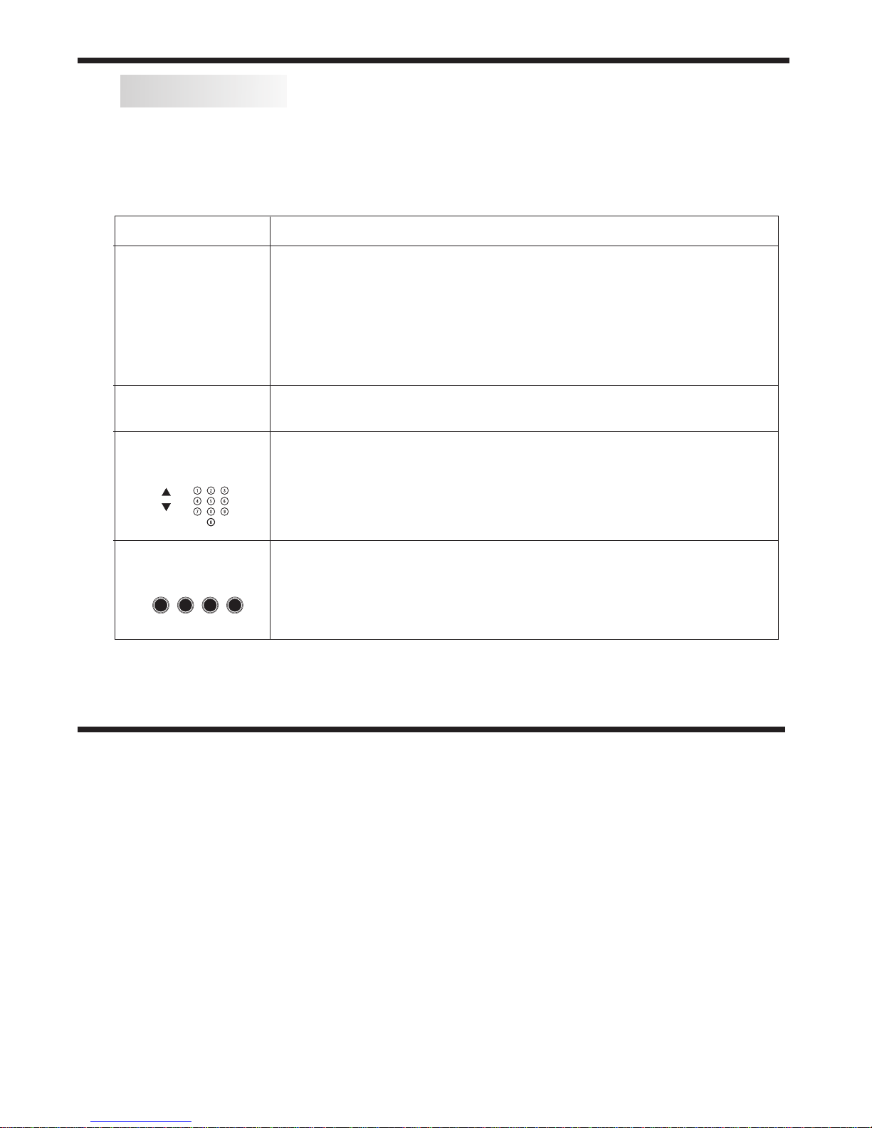
TELETEXT and SUBTITLES
TEXT
DIRECT ACCESS
TO THE ITEMS
Press: You will obtain :
Enter the number of the page required using the 0 to 9 up/down. Example:
page 120, enter 120. The number is displayed top left, the counter turns and
then the page is displayed. Repeat this operation to view another page. If
the counter continues to search, this means that the page is not
transmitted. Select another number.
Coloured buttons correspond to the colours at the bottom of the screen. The
4 coloured keys are used to access the items or corresponding pages. The
coloured areas flash when the item or the page is not yet available.
SELECTING A PAGE
This is used to call or exit teletext modes during ATV reception. The
summary appears with a list of items that can be accessed. Each item has
a corresponding 3 digit page number. If the channel selected does not
broadcast teletext, the indication 100 will be displayed and the screen will
remain blank (in this case, press the CH+ or CH- buttons to check another
text page,or else exit teletext and select another channel).
Teletext is an information system broadcast in certain countries which can be consulted like a
newspaper. It may also offer access to subtitles for viewers with hearing problems or who are not
familiar with the transmission language (Refer to your local TV guides or internet program lists to
determine if Teletext is used in your area.)
SUBTITLE Press this button to select the available sub-title languages during DTV
reception (if any), and to select Subtitle On or Off.
REMOTE CONTROL / GETTING STARTED
-14-
Getting Started :
Once you have connected your TV antenna and other AV playback equipment (eg. CD, DVD, Blu-ray
player) to the appropriate input sockets on the rear and side of the TV, you will need to be comfortable
with selecting several basic operations before setting up your TV using the Menu system.
Firstly, the TV has two power modes – Standby and On. In Standby mode, the TV is powered up, but
awaits a "power On" command from either the Remote Control or from the Standby push-button located
on the lower right-hand side of the TV.
To switch the TV from off into Standby mode, activate the main On/Off rocker switch located at the bottom
mid-right side of the TV, and wait for the Red power indicator on the bottom right of the TV to light up. Then,
press the red power button on the Remote Control to fully activate the TV (ie. move from Standby to On
mode). The power LED on the front of the TV will change from Red to Green colour when the TV is fully
powered up, and after approx 10 seconds the screen will become active and can be commanded using
the Remote Control.
GETTING STARTED

GETTING STARTED
First Powering on the TV :
When you first power up your TV, (or you reset the TV to its factory settings), it will automatically enter the
TV Auto Tuning mode. This is where the TV searches for available TV stations and stores the station details
it finds. Make sure your TV antenna is connected before proceeding with this operation.
By default, an On Screen Display will offer a language selection (pre-set to English), so just press the OK
button on the Remote Control to confirm this option. The OK button is located in the middle of the cursor
arrow button area of the Remote Control.
The TV will then offer a selection of countries, with Australia as the pre-set option. Again press the OK
button to confirm this selection. Your TV will now scan through all the digital TV (DTV) stations that it can
receive using the connected antenna. This process may take several minutes, but once completed, the
TV will skip to the first DTV program.
The “radio” channels found during the TV Auto Tuning function are the sound-only services provided by
some TV stations. This unit does not receive DAB+ Digital Radio broadcasts.
Using the Main Menus :
Once the TV has run through the Auto Tune mode and found the available TV stations, you will then need to
know how to select the relevant input you want (eg. DTV, AV, HDMI etc), and also how to select and adjust
the various Menus that allow you to tailor the operation of the TV to suit your application.
The following pages marked “Menu Settings” will cover the usage and settings of the various menus in
more detail. Please read them carefully to gain the most benefit from your TV.
-15-
Dansk
Deutsch
Hrvatski
Italiano
Please select an OSD Language
OK
Magyar
Nederlands
Norsk
PolskiEnglish
Cesky
E ka
Espanol
~
Fran ais
Portugues
Pycck
Austria
Belgium
Country
OK
Australia
Croatia Finland Greece Luxembourg
Czech France Hungary Netherlands
Bulgaria Denmark Germany Italy
Channel Tuning
TV : 0 Programme(s)
DTV : 0 Programme(s)
Radio : 0 Programme(s)
96% UHF CH 68 DTV
Firstly, on the upper-middle section of the Remote Control are the main cursor selector arrows with the
OK button in the middle of them. Directly above and to the left of the cursor arrows is the Main Menu
selector button, which displays the Main Menus on the TV's screen. In the following section of the User
Manual, when the operation of the options in the Main Menus are being described, you first need to press
the Main Menu button to activate the Menu function, then press the Left or Right cursor arrow buttons to
select the relevant Menu, and the Up or Down cursor arrow buttons to move within the options inside
each Menu. If at any time you mis-select a Menu or setting, press the Exit button (located on the bottom
right-hand side of the cursor arrow buttons) to exit the Menu setting.
Input Source select
Main Menu select
Exit select

MENU SETTINGS
-16-
To access the Input Source menu, where you can select ATV or DTV reception, plus access signals from
your connected Audio/Video devices (eg, via AV Composite video, HDMI, or PC VGA), press the Input
Source button located at the top right-hand side of the cursor selector arrow section of the Remote
Control, and once the Input Source menu appears, use the Up or Down cursor arrow keys to select the
desired input, then press the OK button.
Input Source
DTV
ATV
PC
HDMI1
AV
HDMI2
1.CHANNEL MENU
The first item of the MENU is the Channel menu (for ATV or DTV source only). ATV = Analogue TV, DTV = Digital TV.
2). DTV Manual tuning:
You can select a DTV channel and find out how many programs are being transmitted on that channel.
Press to select the channel, then press OK to search the programs .
NOTE:
The Bad Normal Good bar graph on this screen shows the relative signal intensity during DTV reception only.
To obtain more detail regarding the signal quality and strength of a received DTV station, refer to the Signal
Information option in this Menu.
DTV Manual Tuning
VHF CH 5
_+
Bad Nomal Good
Press OK to search
1). Auto Tuning:
When Auto Tuning is manually selected via the Channel Menu, the TV will default to tuning the DTV stations only
(unless you manually select the other options of ATV or ATV+DTV).
HDMI3
USB
ATV Manual Tuning
Programme Edit
Signal Information
< >
CHANNEL
Auto Tuning
DTV Manual Tuning
Software Update(USB)
Software Update(OAD)
OAD Tuning
Press to select search type, then press to select country (eg. Australia), then press the OK
button to start auto tuning.
All the channels including ATV, DTV and Radio can be tuned at once, if the Tune Type is set to DTV+ATV.
Any previously stored channels will be deleted after auto tuning is carried out.
After auto tuning, the receiver will skip to the first DTV channel.
The radio channels are the ones provided by some TV stations. This unit does not receive DAB+
Digital Radio broadcasts.

3). ATV Manual tuning :
You can change the sound system, search the analog TV channels and fine tune them, then store the
channels you selected. In Australia and New Zealand, select the "BG" sound system. This menu is handy
if you are using your TV to watch analogue signals from a VCR or from older equipment using an RF modulator.
ATV Manual Tuning
Storage To 1
System BG
Current CH 1
Search
Fine-Tune
Frequency 255.25 MHz
Save MENU
_+
NOTE:
Press the red button on the remote control to store the channel details after manual tuning.
4). Program Edit:
You can Delete, Move, Skip, or FAV most TV programs from the list of TV stations previously
located during the initial Auto Tuning process.
-17-
Press to choose the program, press the blue button on the Remote Control to skip this program
from future up/down manual channel selections, and the symbol will show on the right side of the program
name.
Choose the skipped program, press the blue button again, you can cancel the skip and the symbol will
disappear.
Delete
Press t h e red button on the Remote Control and the program in the cursor will be deleted from the
list of stations.To restore a deleted channel, perform a complete Auto Tune.
Favourite
Press to choose the program, press the FAV button on the remote control and it will show a symbol on the
right side of the program name and it will be added to a Favourite List in your TV.
Choose the FAV program, press FAV button again, you can cancel the FAV setting and the symbol will disappear .
Once your Favourite List is created, you can press the FAV key on the remote control during TV reception
to quickly access your favourite channels.
MENU SETTINGS
FAV

-18-
The second item of the MENU is the PICTURE MENU. You can adjust picture effects here, such as contrast,
brightness, etc.
Press to move, press OK to adjust.
2. PICTURE MENU
MENU SETTINGS
5). Signal Information: This screen provides details of the Strength and Quality of only the DTV signals being
received by the TV, and provides a relative score for each function. These readings can be helpful when
investigating possible reception problems and checking the relative performance of your TV antenna and cabling
system. Ideally, the scoring for both Strength and Quality should be as close to 100% as possible (and generally
over 75 – 80%), and the readings should be stable when viewed over short periods. Variations in either reading
may indicate an antenna or cabling issue that requires attention (eg. broken or damaged TV antenna, loose or
damaged cabling, problem with masthead amplifier etc).
6). Software Update (OAD): This setting should be set to Off in Australia.
7). Software Update (USB):
WARNING: Do not attempt to use this option unless you have a valid software program for the GE6993 TV
stored on a compatible USB drive, and the drive is connected to the TV. Remove the antenna cable
from the TV RF socket, go to the channel Menu, select "Software Update (USB)" and press OK to run the update.
Color Temperature
Aspect Ratio
Noise Reduction
Screen
Picture Mode Standard
< >
PICTURE
MENU
Picture Mode Standard
Contrast 50
Brightness 50
Color 50
Sharpness 50
Tint 50
Color Temperature Medium
Red 50
Green 50
Blue 30
MENU
Screen
Auto Adjust
Horizontal Pos.50
Vertical Pos.50
Size 50
phase 38
OK
NOTE:
1). In the Picture Mode sub-menu, the Tint option is available in NTSC system countries only.
2). There are four color temperature modes that can be selected: Medium, Warm, Cool and a User adjusment
option.
3). The Aspect Ratio option allows you to select either Auto, or manually select 4:3, 16:9, Zoom1, Zoom2 or Just
Scan screen ratios. For general use leave this setting in the Auto position.
4). The Screen option is only available once the Input Source is set to PC and a compatible signal is present on
the VGA input socket. Once selected, you can adjust the horizontal and vertical screen position, size and phase
or select an Auto Adjust mode.
5). For improved video processing, access to the Colour adjustment may not be available in the Picture Mode
(User) area when the TV is used with progressive scan video material from externally connected equipment. If
adjustment of the Colour control is required to correct defective source material, change the video mode of your
connected equipment to an interlaced format.
The TV’s default for Picture Mode is the "Standard" setting, which is recommended for home viewing.
6). The Noise Reduction option is more useful for use in areas using ATV (analogue) transmissions. In Australia,
this sub-menu should be set to the Low or Medium position during DTV reception.

< >
Balance
Auto Volume
Sound Mode Standard
SOUND
Surround Sound
SPDIF MODE
3.SOUND MENU
The third item of the MENU is the SOUND MENU.
You can adjust sound effects here such as Treble, Bass, balance etc. Press to move, press OK to adjust.
Note:
4.TIME MENU
The fourth item of the menu is the TIME MENU. You can adjust the clock, power on/off times, sleep timer etc
Press to move, press OK to adjust.
MENU SETTINGS
1) There are five Sound modes that can be selected: Standard, Music, Movie, Sports, and User. The User
option allows you to adjust Bass and Treble sound effects from the TV speakers to suit your listening
preferences. NB. These sound modes are not active on the audio outputs of the AV OUT sockets, or when
using HDMI ARC mode or the Digital Coaxial audio output .
2) The Auto Volume option helps reduce excessive input signal variations that may lead to distorted sound.
For most standard installations, this sub-menu should be set to the Off position.
3) The Surround Sound option generates an artificial widening of the sound stage from the TV. If this sound
effect is not suitable in your installation, leave this sub-menu in the Off position.
4) The SPDIF Mode option affects the format of the Coaxial digital audio output from the socket on the rear of
the TV. Unless you need to force the output format to Bitstream (Auto), leave this setting in the PCM position.
Note:
1) The clock time is automatically set by reading the time data that is transmitted by local Digital TV stations.
2) The Off and On timers allow you to program the TV to switch On and Off at specific times that you set. In
order for this function to operate, the TV must be powered up (ie. mains power switch on the TV is On) and in
Standby mode. The Off and On timers have 6 different setting options: Once, Every Day, Mon – Fri, Mon – Sat,
Sat – Sun, and Sunday. You can set the TV channel and volume settings for most options (except for the Once
setting, where the TV's last channel and volume settings will be used).
3) The Sleep Timer allows you to select from a range of pre-set times (between 10 minutes and 240 minutes
long) that the TV will operate for before returning to the Standby state.
4) The Time Zone setting of the TV is initially set using data from local Digital TV stations.
You can manually adjust the time zone in the TV if required (eg. for locations where DTV signals are not
available).
Off Time
On Time
Sleep Timer
Time Zone
Clock -- -- -- --
TIME
< >
-19-

5.OPTION MENU
To enter the Option Menu, press the MENU button and then press or buttons to select the Option Menu.
Once in Option Menu, press or buttons to select the settings you wish to adjust. Press the MENU button
again to return to the Main Menu.
-20-
MENU SETTINGS
< >
OSD Language English
OPTION
Audio Languages
Subtitle Languages
Hearing Impaired
PVR File System
Restore Factory Default
HDMI CEC
HDMI CEC
Device list
HDMI CEC Off
HDMI ARC Off
Auto Standby On
MENU
Note:
1) The OSD Language option allows you to select the language used in the various TV menus from a wide
selection. At the initial setup stage of the TV, the default language is English, and it is recommended that this
setting is not changed unless you are fluent in any new language chosen.
2) The Audio Languages and Subtitle Languages options relate to DTV reception only. Some TV channels
transmit their audio and subtitles in more than one language, and if this is known in advance, you can select
this alternative language. At the initial setup stage, the default language is English, and it is recommended
that this setting is not changed unless you are fluent in any new language chosen.
3) HDMI CEC (Consumer Electronics Control) allows your TV to share control of some functions with various
compatible equipment via an HDMI cable connection. The HDMI cable connecting your equipment to this TV
must support both ARC and CEC functionality.
For example, with HDMI CEC set to "On" in the TV's menu and also on an HDMI connected device that
supports CEC (eg. a Blu-ray player), selecting the HDMI input on this TV sends a signal to the Blu-ray player
and may switch it On from its Standby state (depending on the player's CEC capabilities).
If the HDMI CEC and Auto Standby options in the HDMI CEC menu are both set to "On" in the TV's Option menu,
and the connected equipment supports the Standby function, then switching On the HDMI connected player
may also switch On the TV from its Standby state. This activity may even set the TV to the HDMI input that the
external device is connected to (again, these examples depend on the capabilities of your connected
equipment).
The HDMI CEC system supports a wide variety of commands, many of which may not be applicable to this TV
or any connected HDMI equipment. Refer to the User Manual of your other equipment to check what areas of
the CEC commands they may be able to work with. If after selecting CEC operation you find the TV or any
connected equipment performing unusually (eg. switching itself back on after you're switched it back to the
Standby mode), your connected equipment may not be compatible with this TV, and the HDMI CEC sub-menu
should be set to the Off position.
4) HDMI ARC (Audio Return Channel) may allow compatible equipment connected to the TV (eg. a Sound Bar)
to receive audio from the TV via a "return" channel in a compatible HDMI cable, so that sound is heard thru the
Sound Bar without having to connect a second cable between the two devices. Some other functions, such as
use of the TV's remote control to control volume on the connected equipment, may also be applicable.
The HDMI cable that connects the TV to the Sound Bar must be a High-speed version which supports both HDMI
CEC and HDMI ARC (or HDMI HEAC) operation in order for the ARC function to operate correctly.
HDMI CEC and HDMI ARC options need to be switched On in the HDMI CEC sub-menu within the main Option
Menu, and any ARC compatible equipment must only be connected to the HDMI 1 input of the TV. Also, the
SPDIF Mode option in the main Sound Menu may need to be set to "PCM" mode to allow ARC operation.
As ARC functionality differs widely between different products and brands, if after selecting ARC operation you
find the TV or any connected equipment performing unusually, turn off the HDMI ARC function and use the
analogue Audio Output sockets or Coax Digital Audio socket on the TV to connect audio to your Sound Bar or
home theatre system.
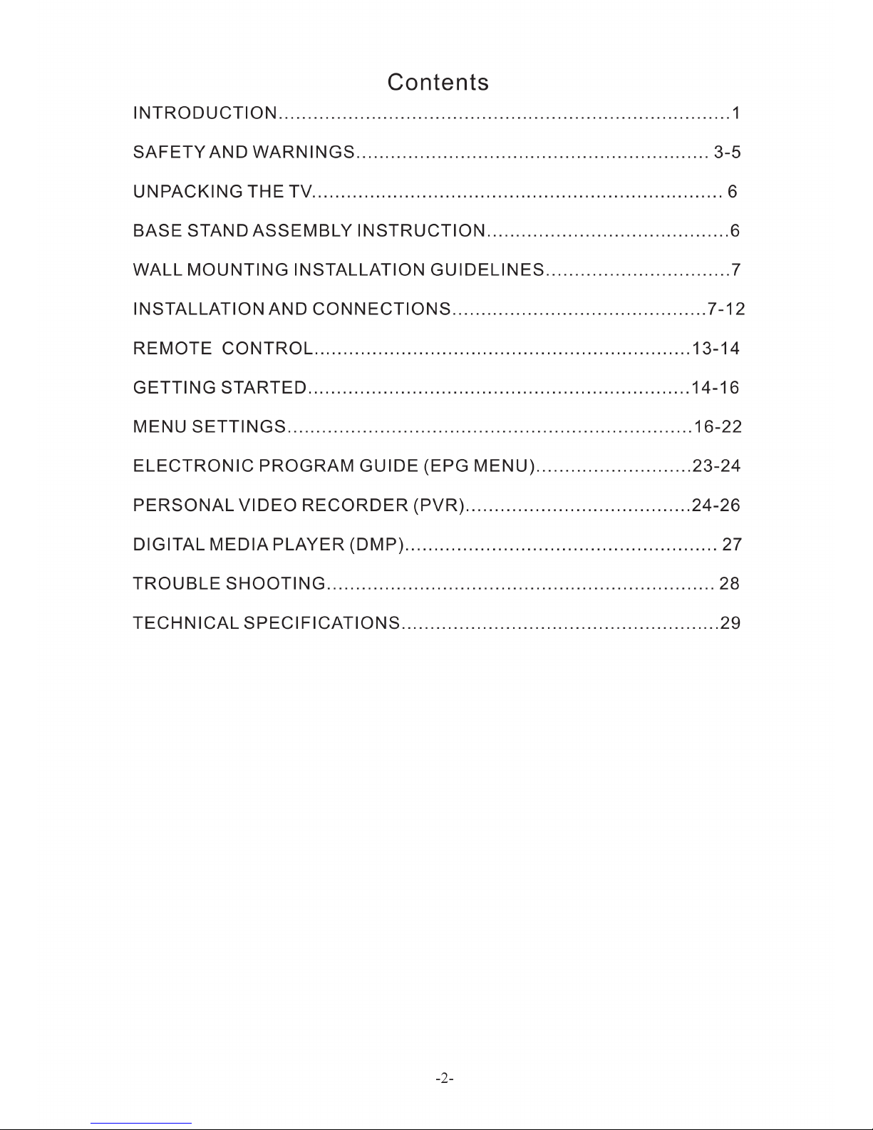
Table of contents


