DIEBOLD NIXDORF K-two User manual

K-two
Installation Guide (1.2.2019)

We would like to know
your opinion on this publication.
Please send us a copy of this page
if you have any constructive criticism on:
- the contents
- the layout
- the product.
We would like to thank you in advance
for your comments.
With kind regards,
Diebold Nixdorf
Wohlrabedamm 31
D-13629 Berlin
e-mail: retail.documentation@dieboldnixdorf.com
_________________________________________________________________________________
Your opinion
Kiosk K-two - Installation Guide
Order No.: 01750299889A

All product names mentioned in this document are registered trademarks.
Copyright © Diebold Nixdorf
All rights including the rights to the translation, reprinting and transmission or copying by any
means, in whole or in part, are reserved.
Offenders will be liable for damages. All rights including rights resulting from a patent grant or
registration of a utility or design are reserved.

Contents
1 Symbols ............................................................................................................................................ 1
2 Warranty .......................................................................................................................................... 2
3 Important Notes............................................................................................................................... 3
3.1 Connecting Peripherals..................................................................................................... 4
4 Overview .......................................................................................................................................... 5
4.1 Exterior view..................................................................................................................... 5
4.2 Interior view ..................................................................................................................... 6
5 Opening the Kiosk ............................................................................................................................ 7
5.1 Opening ............................................................................................................................ 7
6 Dimensions....................................................................................................................................... 8
6.1 Base Plate ......................................................................................................................... 8
6.2 Double-Sided Kiosk (for all display sizes).......................................................................... 9
6.2.1 Service Area ...................................................................................................................... 9
6.3 Single-Sided Kiosk ........................................................................................................... 10
6.3.1 Service Area .................................................................................................................... 10
6.4 Side View Single and Double Sided (for all display sizes) ............................................... 11
6.5 K-two with 22”-display ................................................................................................... 12
6.5.1 On standard and ADA stand ........................................................................................... 12
6.6 K-two with 27”-display ................................................................................................... 13
6.6.1 On low and high pedestal ............................................................................................... 13
6.7 K-two with 32”-display ................................................................................................... 14
6.7.1 Standard ......................................................................................................................... 14
6.7.2 Short ............................................................................................................................... 15
6.7.3 Pole ADA ......................................................................................................................... 16
7 Assembling Instructions: Wall Mounted Kiosk .............................................................................. 17
7.1 Recommendation for wall mounting.............................................................................. 17
7.2 Installation Kits and Dimensions..................................................................................... 19
7.2.1 Wall mounting bracket 22”: ........................................................................................... 19
7.2.2 Wall mounting bracket 27”: ........................................................................................... 20
7.2.3 Wall mounting bracket 32”: ........................................................................................... 21
7.3 Installation ...................................................................................................................... 22
8 Assembling Instructions: Pole-Mounted Kiosk .............................................................................. 26
8.1 Recommendation for floor mounting ............................................................................ 26

8.2 Kiosk with Floor Cabling.................................................................................................. 27
8.3 Kiosk with Over-Floor Cabling ........................................................................................ 31
8.4 Kiosk with Ceiling Cabling ............................................................................................... 35
8.5 Attach Cable Duct ........................................................................................................... 36
9 Pole light (K-two 32” only) ............................................................................................................. 39
10 EFT (Electronic-Funds-Transfer)-Terminal ..................................................................................... 41
11 MX915............................................................................................................................................ 44
12 Ingenico IUP/IUR 250/IUC 150....................................................................................................... 46
12.1 Installation ...................................................................................................................... 47
13 Pin Pad UX 100/200/300................................................................................................................ 50
13.1 Installation ...................................................................................................................... 51
14 CCV C60.......................................................................................................................................... 55
14.1 Installation ...................................................................................................................... 56
15 ICT 220/250.................................................................................................................................... 60
16 Start up the System........................................................................................................................ 63
17 Disconnecting the System from the Mains.................................................................................... 64
18 Permanent connection (North America) ....................................................................................... 65
18.1 Connection line............................................................................................................... 65
18.2 Wiring from above.......................................................................................................... 65
18.3 Wiring from below.......................................................................................................... 68
19 Block diagram................................................................................................................................. 71
20 Technical data ................................................................................................................................ 72
20.1 System ............................................................................................................................ 72
20.2 Environmental requirements ......................................................................................... 73
20.3 Electrical characteritics of the power supply ................................................................. 73
20.4 Device conditions............................................................................................................ 74
20.5 Noise emission in acc. With EN 27779 ........................................................................... 74
20.6 ACO Kiosk PC................................................................................................................... 74
20.7 Display 22” (TEM-22F-PUG-15-C) Display 27“ (TEF-27F-PUK-15A- C)
Display 32” (TDS-32C-PUK-15A-C) ......................................................................................... 75
20.8 TH230+............................................................................................................................ 76
21 Certifications of the Manufacturer ................................................................................................ 78
22 Recycling the Kiosk......................................................................................................................... 79

1
1Symbols
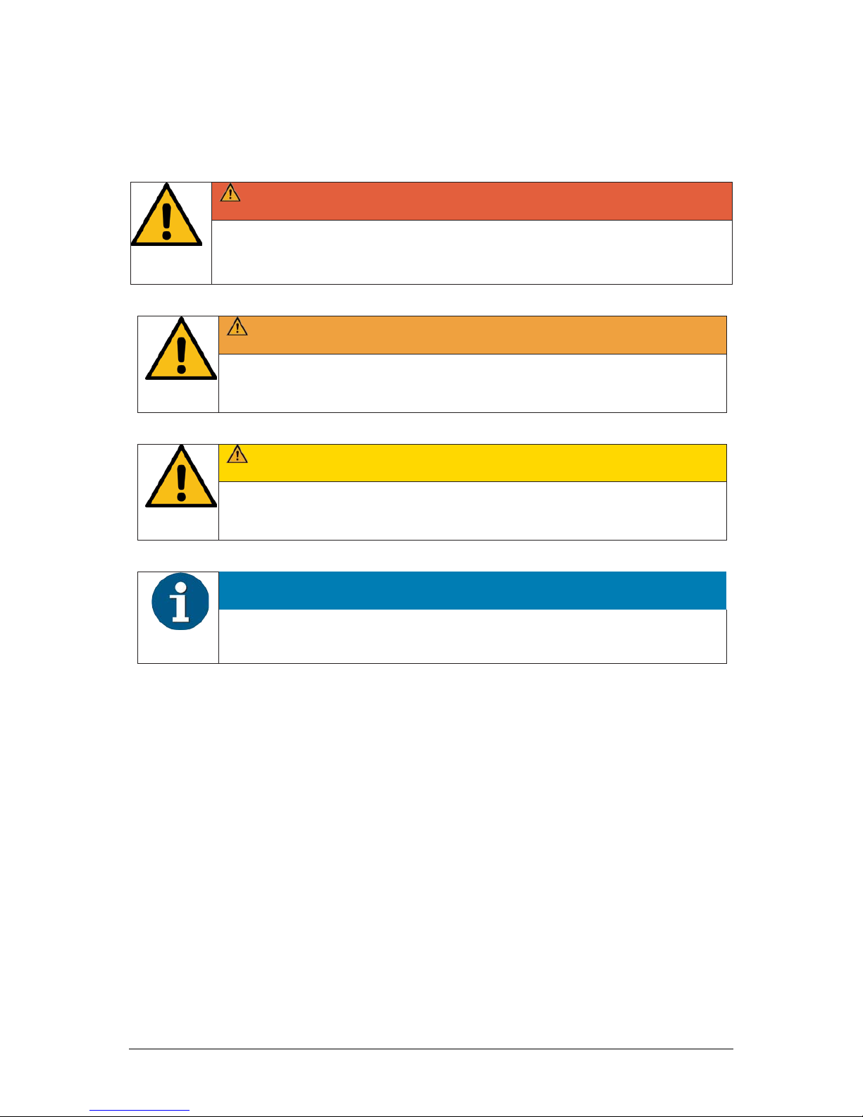
DANGER
This warning note describes a hazard with a high degree of risk, which, if not
avoided, will result in death or grave bodily injury.
WARNING
This warning note describes a hazard with a medium degree of risk, which, if
not avoided, will result in death or grave bodily injury.
CAUTION
This warning note describes a hazard with a low degree of risk, which, if not
avoided, will result in death or grave bodily injury.
NOTICE
This note provides application tips and information that help prevent errors and
material damage.

2
2Warranty
Generally Diebold Nixdorf guarantees a warranty engagement for 12 months beginning with the date
of delivery. This warranty engagement covers all damages which occur despite a normal use of the
product.
Damages because of
•improper or insufficient maintenance,
•improper use of the product or unauthorized modifications of the product,
•inadequate location or surroundings
will not be covered by the warranty.
For further information on the stipulation consult your contract.
All parts of the product which are subject to wear and tear are not included in the warranty engage-
ment. For detailed warranty arrangements please consult your contract documents.
NOTICE
Please contact your local service provider for all questions concerning your service
contract.
3
3Important Notes
Terminals supplied by Diebold Nixdorf comply with the respective safety regulations for data-
processing installations and information technology installations, including electrical office equip-
ment for use within an office environment.
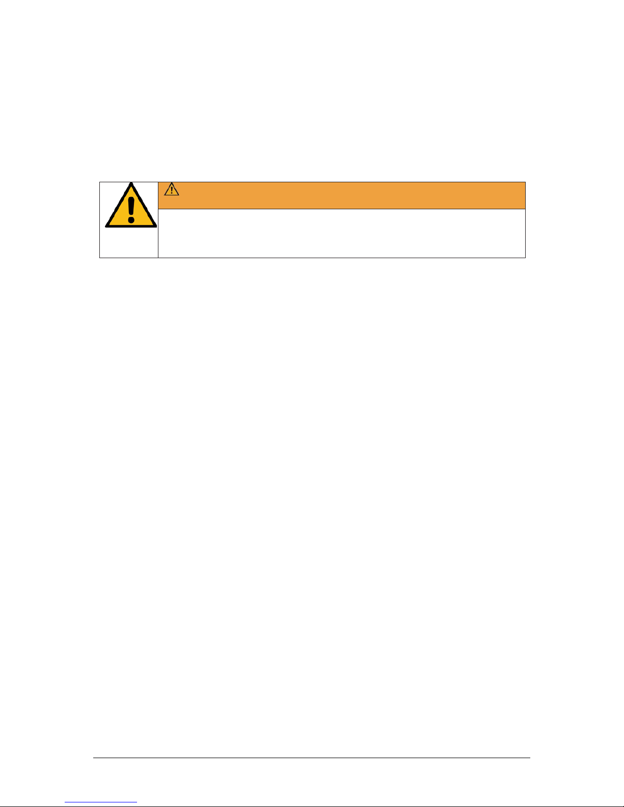
WARNING
Whenever work of any kind is done on the device, as well as when data cables
are plugged and unplugged, the device must be completely disconnected from
the line voltage.
•Terminals may only be installed and repaired by skilled technicians.
•Unauthorized opening of the housing or inexpert repairs can result not only in considerable per-
sonal danger, but will also invalidate your warranty and liability protection.
•Always consult the enclosed documentation before doing any work with this terminal.
•If this terminal is brought from a cold environment into a heated place of business, condensation
may occur. Before operation, the terminal must be completely dry. Therefore, an acclimatization
period of at least two hours must be adhered too.
•Always lay the supply leads and cables in such a way that they cannot be stepped on or tripped
over.
•Exchange damaged cables immediately.
•In order to completely disconnect the terminal from the power source use the separator in the
fuse box\building installation.
•Make sure that no objects (such as paper clips) can reach the interior of the terminal, since elec-
trical shocks or short-circuits could result.
•Ensure that the K-two receives adequate ventilation to avoid overheating.
•During an electrical storm, data cables should not be plugged in or being unplugged.
•Keep the terminal away from vibrations, dust, humidity and heat.
•Ensure that used parts are disposed of in an environmentally friendly manner.
•In case of an accident (such as a damaged housing, entry of liquids or foreign objects), switch the
terminal off and use the separator to completely remove the terminal from power.
•The terminal and other information technology hardware should only be connected to electrical
supply networks with a separate protective earth wire (PE). This type of electrical supply network
is referred to as a TN-S network. Do not use PEN conductors. Also follow the recommendations
set forth in DIN VDE 0100 Part 540, Appendix C2 as well as EN50174-2, §5.4.3 (www.DIN.de). This
will help prevent malfunctions.

4
•National Electrical Code ANSI/NFPA 70-2005
•Canadian Electrical Code, Part I, CSA C22.1-02
•Always keep the ventilation slots free of obstruction to ensure adequate air circulation and avoid
overheating.
•Transport the terminal only in its original packaging (to protect it against knocks and bumps).
•If a lithium battery is supplied with the terminal, ensure that the battery is replaced with an
equivalent type. Otherwise there is danger of explosion! Lithium batteries may only be replaced
with identical types or other types recommended by the manufacturer.
•Batteries must be disposed of according to local regulations on the disposal of special waste.
3.1 Connecting Peripherals
Use only shielded cables when connecting terminals to the system to ensure compliance with inter-
national Rules and Regulations for radiated emission as well as to achieve a high immunity against
external disturbances.
5
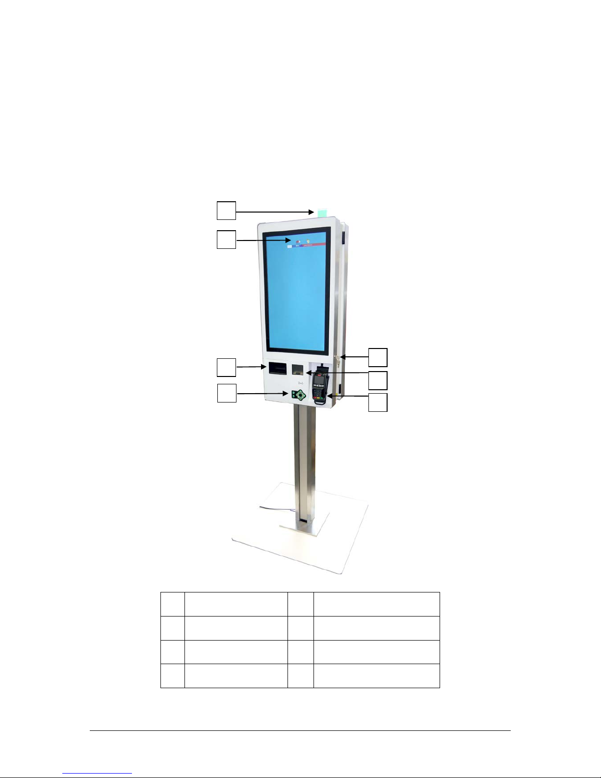
4Overview
4.1 Exterior view
1 Pole Light 5 Lock
2 Display 6 Scanner
3 Printer 7 EFT*
4 ADA Navigation
* It may be connected ETFs with 12V for max. current consumption of 1.1A (permanent).
1
3
2
4
5
6
7
6
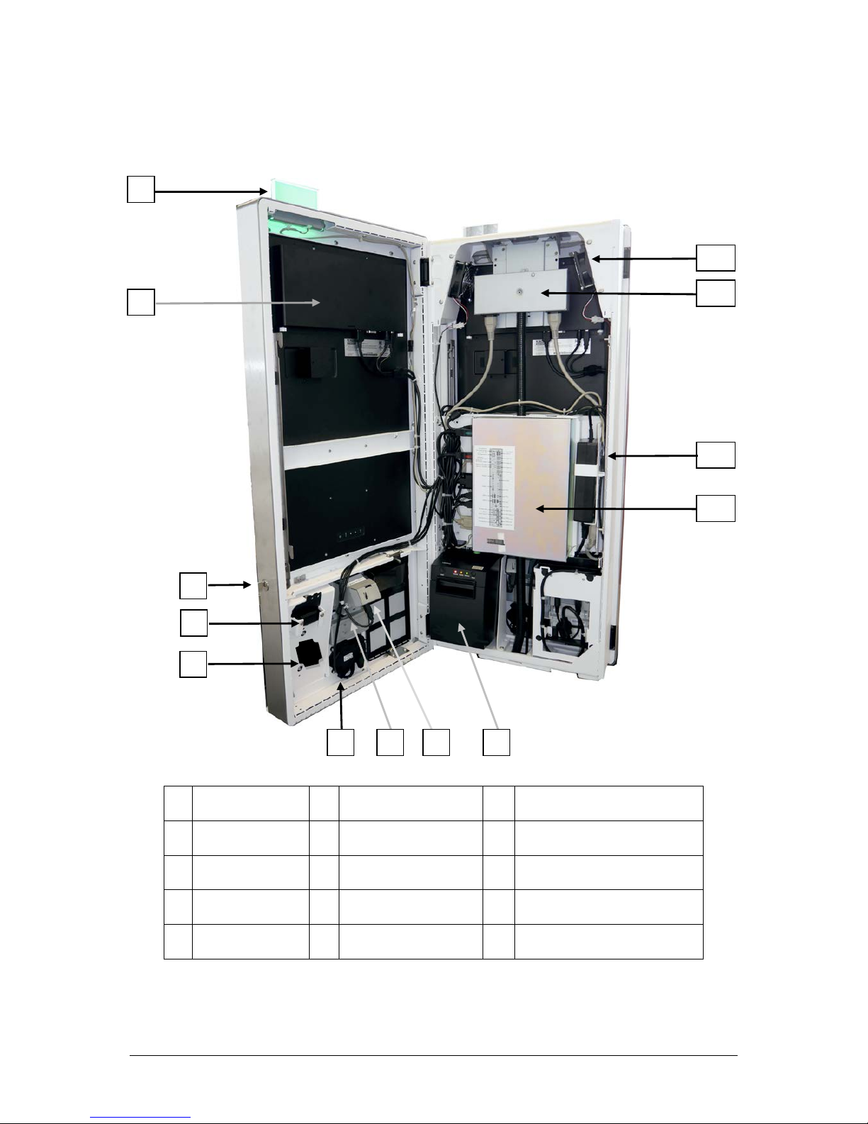
4.2 Interior view
1 Pole Light 6 ADA Navigation 11 Power Distributor
2 Display 7 NFC Module 12 Power Supply only USA/CAN
3 Lock 8 Scanner 13 PC
4 EFT* 9 Printer
5 Speaker 10 Fan
* It may be connected ETFs with 12V for max. current consumption of 1.1A (permanent).
1
3
2
4
5
10
6
7
8
9
11
13
12
7
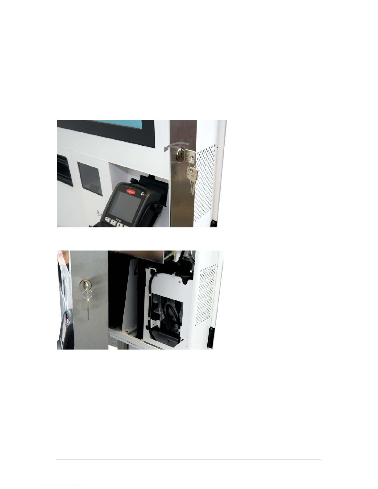
5Opening the Kiosk
5.1 Opening
Plug the key to the lock and turn it counter clockwise.
Open the door.

8
6Dimensions
6.1 Base Plate

9
6.2 Double-Sided Kiosk (for all display sizes)
6.2.1 Service Area

10
6.3 Single-Sided Kiosk
6.3.1 Service Area
11
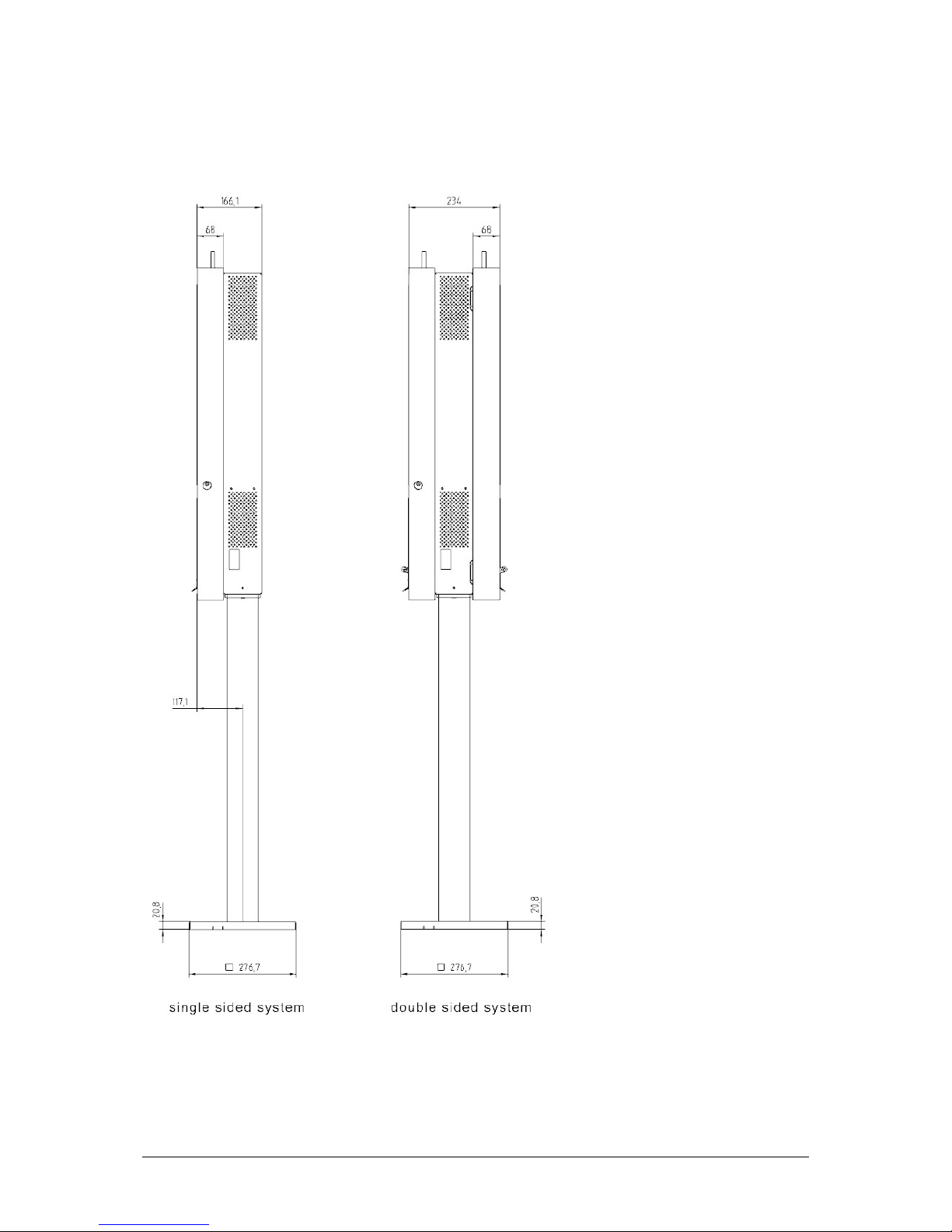
6.4 Side View Single and Double Sided (for all display sizes)
12
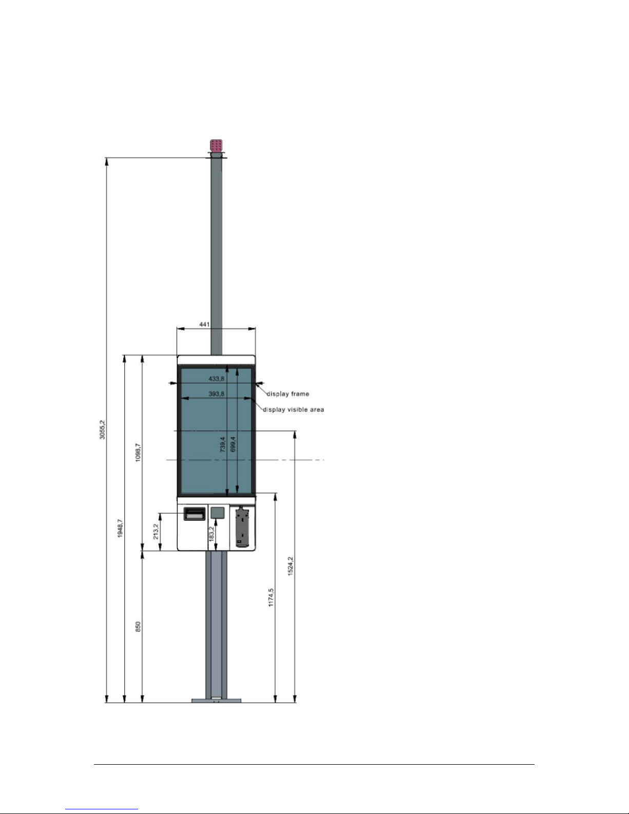
6.5 K-two with 22”-display
6.5.1 On standard and ADA stand
K2 shown with standard kit for ceiling cabling, it can be enlarged up to two times with 1.151mm
expansion kits.
13
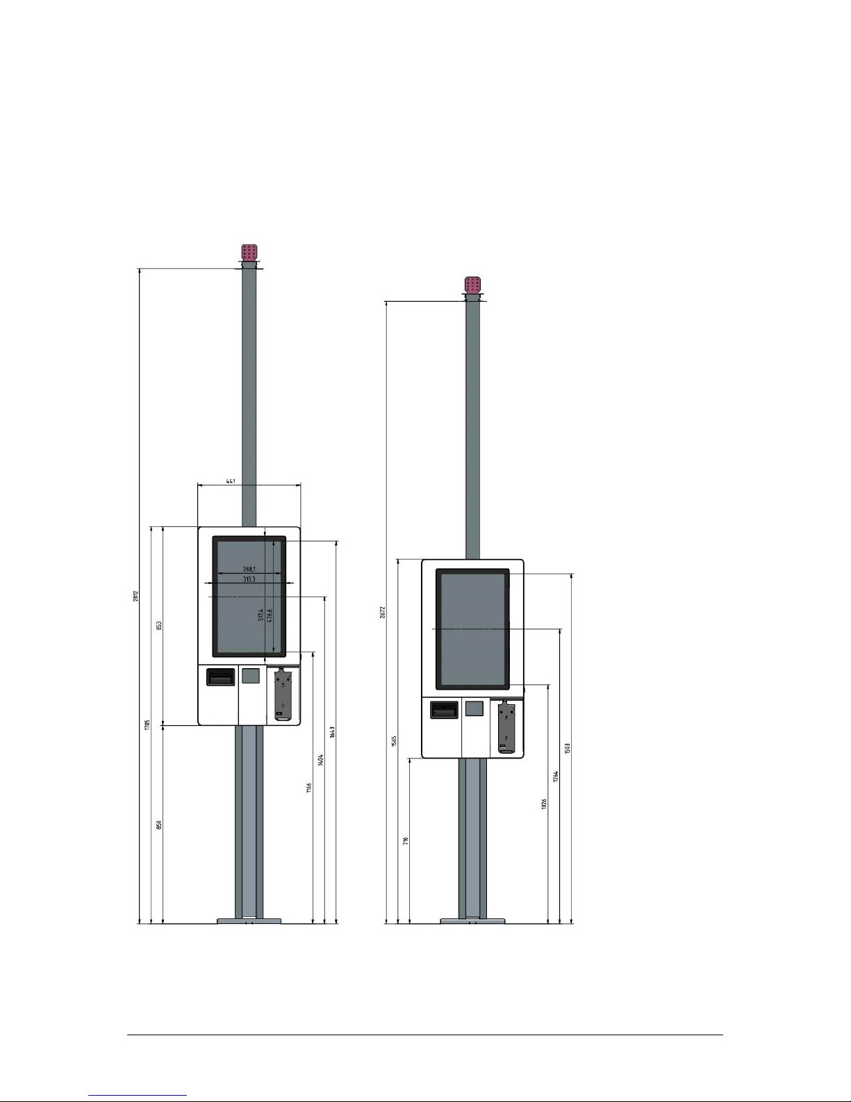
6.6 K-two with 27”-display
6.6.1 On low and high pedestal
K2 shown with standard kit for ceiling cabling, it can be enlarged up to two times with 1.151mm ex-
pansion kits.
14
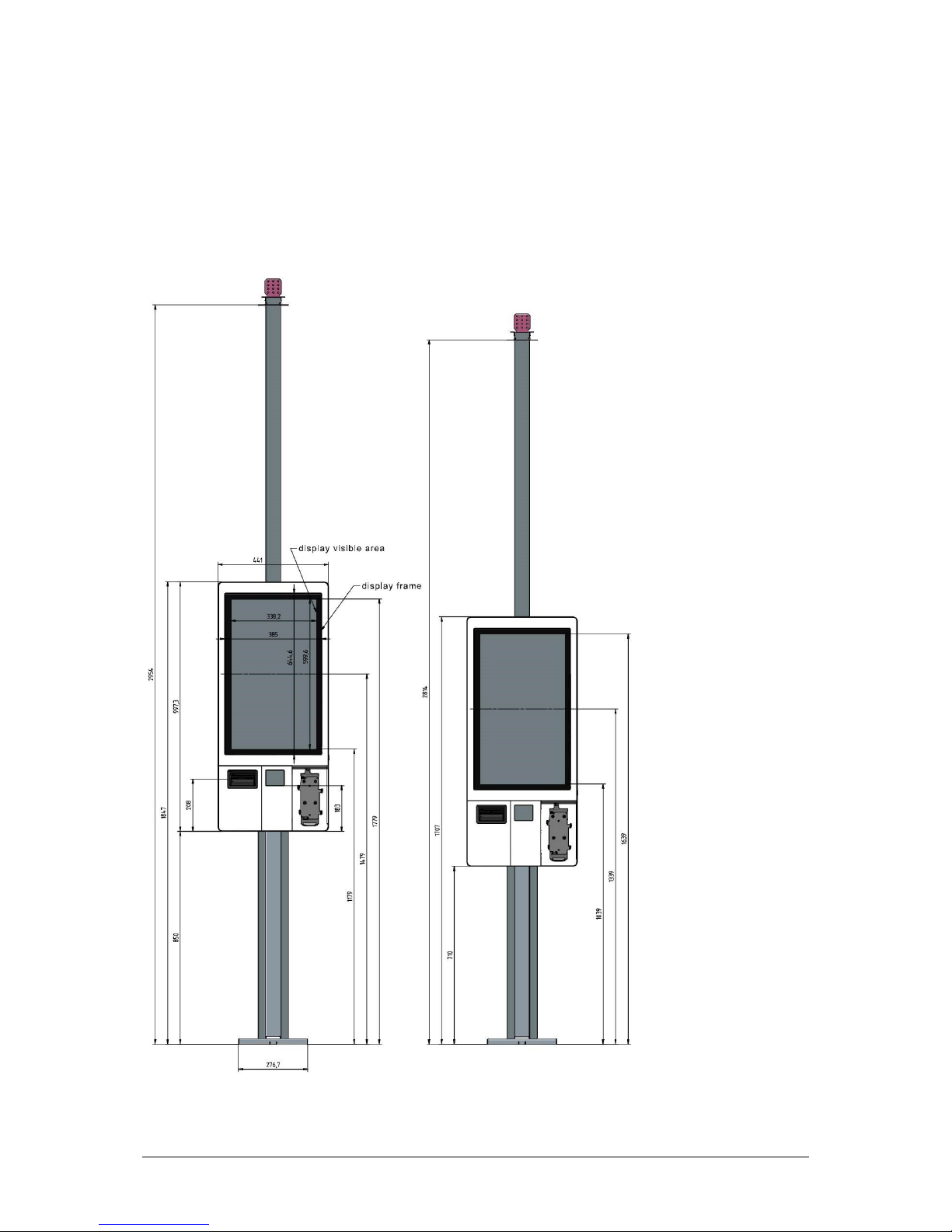
6.7 K-two with 32”-display
6.7.1 Standard
Other manuals for K-two
3
Table of contents


