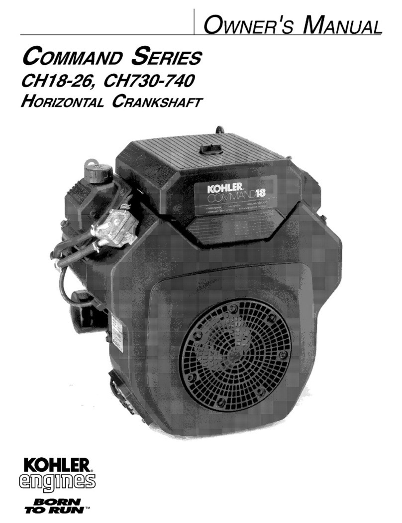
Diesel WARTSILA F 240 User manual

Manual

ECopyright 2004 by Wärtsilä Nederland B.V.
All rights reserved. No part of thisbooklet may be reproduced or copied in anyform
or by any means (electronic, mechanical, graphic, photocopying, recording, taping
or other information retrieval systems) without the prior written permission of the
copyright owner.
THISPUBLICATIONISDESIGNEDTOPROVIDEASACCURATEANDAUTHORITATIVEINFORMATION
IN REGARD TO THE SUBJECT---MATTER COVERED AS WAS AVAILABLE AT THE TIME OF WRITING.
HOWEVER, THE PUBLICATION DEALS WITH COMPLICATED TECHNICAL MATTERS SUITED ONLY
FOR SPECIALISTS IN THE AREA, AND THE DESIGN OF THE SUBJECT---PRODUCTS IS SUBJECT TO
REGULAR IMPROVEMENTS, MODIFICATIONS AND CHANGES. CONSEQUENTLY, THE PUBLISHER
AND COPYRIGHT OWNER OF THIS PUBLICATION CAN NOT ACCEPT ANY RESPONSIBILITY OR LIA-
BILITY FOR ANY EVENTUAL ERRORS OR OMISSIONS IN THIS BOOKLET OR FOR DISCREPANCIES
ARISING FROM THE FEATURES OF ANY ACTUAL ITEM IN THE RESPECTIVE PRODUCT BEING DIF-
FERENT FROM THOSE SHOWN IN THIS PUBLICATION. THE PUBLISHER AND COPYRIGHT HOLDER
SHALL UNDER NO CIRCUMSTANCES BE HELD LIABLE FOR ANY FINANCIAL OR OTHER LOSS, OR
ANY OTHER DAMAGE OR INJURY, SUFFERED BY ANY PARTY MAKING USE OF THIS PUBLICATION
OR THE INFORMATION CONTAINED HEREIN.
--
Date of issue November 2004
ENGINE TYPE F 240 --engine
Author SERVICE
Approved
AUTHORIZATION Management WNL
DOCUMENT
13128
Distribution
Status
Number
Manual

Manual
F 240 COMMUNICATION
Ver. 01 xx -- 3
In order to maintain the operational safety of your engine, a simple, and a fast contact
between you and Stork--Wärtsilä Diesel B.V can be of essential importance.
Stork--Wärtsilä Diesel B.V.
Postbus 10608
8000 GB ZWOLLE
Telefoon 038--4253253
Telex 42116
FAX 038-- 4223564
From Monday to Friday Stork--Wärtsilä Diesel B.V can be contacted on telephone
number 038--4253 253 during working hours from 08.00 -- 16.30 hours; ask for
departments:
-- SERVICE-- PARTS:
For information about inquiries, information about service, ordering spare parts
or tools
-- SERVICE --INSPECTION:
For all technical support.
During non--working hours one of our staff members will always be available on the
above number. He will have one of our experts to call you back as soon as possible.
Furthermore youcan contact one ofour Service Departments inThe Netherlands dur-
ing working hours as mentioned below:
SCHIEDAM (ROTTERDAM)
DEN HELDER
STELLENDAM
URK (only on Saturday)
IJMUIDEN
For information on Service Departments throughout the world, please contact Stork--
Wärtsilä Diesel B.V. headquaters, Zwolle.
-- o -- o -- o -- o -- o --
Introduction
Headquarters
in The
Netherlands
Service
departments in
the Netherlands
Service depart-
ments through-
out the world
Hanzelaan 95
8017 JE ZWOLLE
Tel.: 010 -- 4 277 100
Adres: Havenstraat 24
Fax: 010 -- 4 264 571
Tel.: 0223 -- 33 59 88
Adres:Het NieuweWerk102
Fax: 0223 -- 333890
Tel: 0187 -- 491956
Adres: Deltahaven 7
Fax: 0187 -- 493428
Tel: 0527 -- 682053
Adres: Industrierondweg 6D
Tel.: 0255 -- 511678
Adres: Trawlerkade 46
Fax: 0255 -- 536724

Manual
F 240 COMMUNICATION
Ver. 01 xx -- 4

Manual
F 240 CONTENTS
xx -- 5
Ver. 01
CHAPTER 0: GENERAL
0A PURPOSE 0--1..............................................................
0B DOCUMENTATION OVERVIEW 0--2...........................................
0C MANUAL SETUP/PAGE SETUP 0--3..........................................
1. Manual setup 0--3........................................................
2. Page setup 0--3..........................................................
0D DESCRIPTION OF THE ENGINE 0--5.........................................
1. Crankshaft and bedplate 0--5.........................................
2. Cylinder block 0--5...................................................
3. Cylinder liner 0--5....................................................
4. Piston with connecting rod 0--5.......................................
5. Cylinder head 0--5...................................................
6. Camshaft and valve mechanism 0--5..................................
7. Injection equipment 0--6..............................................
8. Exhaust manifold 0--6................................................
9. Turbocharging and charge air cooling 0--6.............................
10.Definitions 0--6......................................................
CHAPTER 1: OPERATION
1A GENERAL 1--1.............................................................
1. Commissioning 1--1....................................................
2. General 1--1...........................................................
3. Starting and stopping of the engine 1--1.................................
4. Operation 1--1.........................................................
5. Running--in 1--1........................................................
6. During operation 1--1...................................................
7. After stopping 1--2.....................................................
8. Long shut--downs 1--2..................................................
CHAPTER 2: BACKGROUND INFORMATION
2A SAFETY ASPECTS 2--1.....................................................
1. Safety aspects 2--1.....................................................
Risk of crankcase explosion 2--1..........................................
2. Maintenance instructions 2--1...........................................
General 2--1............................................................
Removal 2--2...........................................................
Fuel injector 2--2........................................................
Mounting 2--2...........................................................
Last check 2--2.........................................................
2B CRANK DEGREES NINE CYLINDER ENGINE 2--3.................................
1. General 2--3...........................................................
2. Reading crank position 2--3.............................................
2C ENGINE TOOLS 2--4............................................................
1. General 2--4...........................................................
2. Tool 9612 F 927 2--4....................................................
2D INDEX OF SYMBOLS 2--5.......................................................

Manual
F 240 CONTENTS
xx -- 6
Ver. 01
CHAPTER 3: TECHNICAL DATA
3A MAIN DATA 3--1............................................................
1. Engine specifications 3--1..............................................
2. Weights in kg. 3--1.....................................................
3. Oil contents in liters 3--1................................................
4. Cooling water in liters 3--1.............................................
5. Cylinder numbers 3--2..................................................
6. Combustion sequence 3--2.............................................
7. Standard valve timing 3--2..............................................
8. Valve clearance 3--2....................................................
9. Pressures 3--3.........................................................
10. Temperatures 3--3......................................................
11. Pump data 3--3.........................................................
3B TIGHTENING TORQUES 3--4.................................................
1. Cylinder head 3--4......................................................
2. Cylinder block 3--4.....................................................
3. Fuel 3--4...............................................................
4. Camshaft 3--5..........................................................
5. Connecting rod 3--5....................................................
6. Main bearings 3--5.....................................................
7. Crankshaft 3--5........................................................
8. Engine/generator on foundation 3--5....................................
9. Assembly tie rods 3--6..................................................
3C NO GO CRITERIA 3--8......................................................
1. Piston (2--parts conf.) 3--8..............................................
2. Connecting rod 3--8....................................................
3. Main bearing (with mounted cylinder block) 3--8.........................
4. Axial bearing 3--8......................................................
5. Camshaft 3--9..........................................................
6. Camshaft drive 3--9....................................................
7. Valves (inlet and exhaust) 3--9..........................................
8. Lubricating oil pump 3--9...............................................
CHAPTER 4: INJECTION AND MAINTENANCE
4A GENERAL 4--1..............................................................
1. General 4--1...........................................................
2. Daily check 4--1........................................................
3. Weekly check 4--2......................................................
4. Observation list 4--3....................................................
4B INSPECTION AND MAINTENANCE PROCEDURES 4--4........................
1. Maintenance interval/effective life 4--4...................................
2. Inspection 4--4.........................................................
3. Daily maintenance 4--5.................................................
4. Weekly maintenance 4--6...............................................
5. 750--hours overhaul 4--7................................................
6. 1500--hours overhaul 4--8...............................................
7. 3000--hours overhaul 4--9...............................................
8. 6000--hours overhaul 4--10...............................................
9. 12000--hours overhaul 4--12..............................................
10. 24000--hours overhaul 4--14..............................................
11. 36000--hours overhaul 4--16..............................................
4C TEST RUNNING 4--18........................................................
1. Test running 4--18.......................................................
2. Running--in 4--18........................................................
3. Functional test 4--20.....................................................

Manual
F 240 CONTENTS
xx -- 7
Ver. 01
CHAPTER 5: FUEL SYSTEM
5A INTRODUCTION 5--1........................................................
1. General 5--1...........................................................
2. Description of engine parts 5--1.........................................
Fuel feed pump (1.1) 5--1................................................
Fine fuel filter (1.2) 5--1..................................................
High pressure fuel pumps (1.3) 5--1........................................
Fuel injector (1.5) 5--2...................................................
Pressure regulating valve (1.6) 5--2........................................
Leak--off fuel (2.1, 2.2 and 2.3) 5--2........................................
5B FUEL REQUIREMENTS 5--3.................................................
Bunker requirements 5--3................................................
Engine fuel requirements 5--3.............................................
5C FUEL FILTER ELEMENT 5--4.................................................
1. General 5--4...........................................................
2. Removal 5--4...........................................................
3. Fitting 5--5.............................................................
5D INSPECTIONS, MOMENT OF INJECTION 5--6.................................
1. Training tools 5--6......................................................
2. Fuel control system 5--7................................................
3. Verification of moment of injection 5--8..................................
4. Checking pre--lifting 5--9................................................
5E CONSTANT PRESSURE VALVE 5--10..........................................
1. Tool 5--10...............................................................
Tool A 5--10.............................................................
Tool B 5--10.............................................................
2. Testing 5--10............................................................
5F GENERAL DIAGRAM 5--11....................................................
CHAPTER 6: LUBRICATING OIL SYSTEM
6A INTRODUCTION 6--1........................................................
1. General 6--1...........................................................
2. Description of engine parts 6--1.........................................
Lubricating oil pump (1.0) 6--1............................................
Thermostatic three--way valve (1.2) 6--1....................................
Safety overflow valve (1.3) 6--1...........................................
Pressure regulating valve (1.6) 6--1........................................
Main lubricating oil manifold (1.7) 6--2......................................
Pre--lubricating pump (4.0) 6--2...........................................
Needle valve (5.6) 6--2...................................................
Crankcase venting (A) 6--2...............................................
6B LUBRICATING OIL REQUIREMENTS 6--3.....................................
1. General 6--3...........................................................
2. Engine lubricating oil 6--3..............................................
3. Sub--suppliers manuals 6--3............................................
4. Testing engine lubricating oil 6--4.......................................
5. No go criteria for engine lubricating oil 6--4..............................
6C LUBRICATING OIL FILTER 6--5..............................................
1. General 6--5...........................................................
2. Removing 6--6.........................................................
3. Assembly 6--6.........................................................
6D CENTRIFUGAL FILTER 6--7..................................................
1. General 6--7...........................................................
2. Disassembly 6--7.......................................................
3. Replacement 6--7......................................................
6E LUBRICATION OF INLET VALVE SEATS 6--9..................................
1. General 6--9...........................................................
2. Checking 6--9..........................................................

Manual
F 240 CONTENTS
xx -- 8
Ver. 01
6F BARRIER OIL SYSTEM HIGH PRESSURE FUEL PUMPS 6--10...................
1. General 6--10...........................................................
2. Checking the barrier oil system HP fuel pumps 6--10......................
6G INSPECTIONS 6--11..........................................................
1. Lubricating oil overflow valves 6--11......................................
6H LUBRICATING OIL THERMOSTATS 6--12......................................
1. General 6--12...........................................................
2. Inspection of the thermostatic wax elements 6--12........................
6J GENERAL DIAGRAM 6--13....................................................
CHAPTER 7: COOLING WATER SYSTEM
7A INTRODUCTION 7--1........................................................
1. General 7--1...........................................................
2. Description of engine parts HT--circuit 7--1...............................
Cooling water pump (1.0) 7--1.............................................
De--aeration points (1.3) 7--1..............................................
Thermostatic 3--way valve (1.4) 7--1.......................................
Water cooler (1.5) 7--1...................................................
Cooling water expansion tank (1.7) 7--1....................................
Emergency cooling (E) 7--1...............................................
3. Description engine parts LT--circuit 7--2.................................
Cooling water pump (2.0) 7--2.............................................
Charge air cooler (2.3) 7--2...............................................
Lube oil cooler (2.4) and water cooler (1.5) 7--2.............................
Emergency cooling LT--circuit 7--2.........................................
7B REQUIREMENTS 7--3.......................................................
1. Cooling water specifications 7--3........................................
2. Cooling water treatments 7--4...........................................
3. Checking of cooling water quality 7--5...................................
7C COOLING WATER DE--AERATION 7--6........................................
General 7--6............................................................
Checking and inspection 7--6.............................................
7D COOLERS 7--7.............................................................
1. Heat exchangers 7--7...................................................
2. Air cooler 7--7..........................................................
Insufficient cooling 7--7...................................................
7E COOLING WATER THERMOSTATS 7--8.......................................
7F COOLING WATER PUMP 7--9................................................
1. Disassembly 7--9.......................................................
2. Assembly 7--10.........................................................
7G INSPECTION COOLING WATER SPACE 7--11..................................
7H GENERAL DIAGRAM 7--12....................................................
CHAPTER 8: AIR INLET AND EXHAUST SYSTEM
8A INTRODUCTION 8--1........................................................
1. General 8--1...........................................................
2. Description of engine parts 8--1.........................................
Inlet air filter (1.1) 8--1...................................................
Turbocharger (1.2) 8--1..................................................
Air cooler (1.4) 8--2......................................................
Exhaust manifold (2.1) 8--2...............................................
8B COMBUSTION AIR REQUIREMENTS 8--3.....................................
1. Specification 8--3......................................................
Reference conditions 8--3................................................
2. Receiver pressure and exhaust gas temnperature 8--3....................
8C CHARGE AIR CONDENSATION 8--4..........................................
1. Checking discharge opening 8--4.......................................
2. Inspection discharge 8--4...............................................

Manual
F 240 CONTENTS
xx -- 9
Ver. 01
8D TURBOCHARGER 8--5......................................................
1. General 8--5...........................................................
2. Cleaning compressor side 8--5..........................................
3. Cleaning of the air filter 8--6............................................
8E EXHAUST COMPENSATORS 8--7............................................
1. Necessary tools 8--7....................................................
2. Fitting of the compensator 8--7..........................................
8F GENERAL DIAGRAM 8--8....................................................
CHAPTER 9: STARTING AND STOPPING SYSTEM
9A INTRODUCTION 9--1........................................................
1. General 9--1...........................................................
2. Description of engine parts 9--1.........................................
Starting device (1.--) 9--1.................................................
Stopping device (2.--) 9--1................................................
9B STARTING PROCEDURE 9--2................................................
1. Prior to starting 9--2....................................................
Fuel system 9--2........................................................
Cooling water system 9--2................................................
Start and stop system 9--2................................................
Alarm system 9--2.......................................................
Lubricating oil system 9--2................................................
2. Starting 9--2...........................................................
3. Stopping 9--2..........................................................
9C STARTING AIR DISTRIBUTOR 9--3...........................................
1. Replacing the driver 9--3................................................
2. Checking the setting 9--3...............................................
3. Setting the distributor disc 9--4.........................................
9D GENERAL DIAGRAM 9--5....................................................
CHAPTER 10: ALARM AND SAFETY SYSTEM
10A DESCRIPTION 10--1..........................................................
1. General 10--1...........................................................
2. Speed measuring system 10--1...........................................
3. Alarm and protection switches 10--3......................................
4. Alarm and protection unit 10--4..........................................
5. Co--signaling board 10--5................................................
10B TESTING THE SETTINGS 10--6...............................................
1. General 10--6...........................................................
2. Test, checks and calibrations 10--6.......................................
10C DIAGRAM RPM MEASURING SYSTEM 10--8...................................
10D DIAGRAM ALARM AND SAFETY 10--10.........................................
CHAPTER 11: MAIN BEARINGS
11A NECESSARY TOOLS 11--1....................................................
Tool A 11--1.............................................................
Tool B 11--2.............................................................
Tool C 11--3.............................................................
11B REMOVAL 11--4..............................................................
11C REPLACEMENT 11--5........................................................
CHAPTER 13: CYLINDER BLOCK
13A INTERNAL INSPECTION 13--1................................................
1. Crankshaft space 13--1..................................................
2. Cooling water spaces 13--1..............................................

Manual
F 240 CONTENTS
xx -- 10
Ver. 01
CHAPTER 14: EXPLOSION VALVE
14A CHECKING 14--1.............................................................
CHAPTER 15: CYLINDER LINER
15A NECESSARY TOOLS 15--1....................................................
Tool A 15--1.............................................................
15B INSPECTION 15--2...........................................................
1. Endoscope inspection 15--2.............................................
2. Inspection points 15--2..................................................
15C REMOVAL 15--3..............................................................
Tool A 15--3.............................................................
15D FITTING 15--4................................................................
CHAPTER 16: PISTON AND CONNECTING ROD
16A GENERAL DESCRIPTION 16--1...............................................
1. Piston 16--1.............................................................
2. Connecting rod 16--1....................................................
16B NECESSARY TOOLS 16--2....................................................
Tool A 16--2.............................................................
Item 1 16--2.............................................................
Item 2 16--3.............................................................
Item 3 16--3.............................................................
Item 4 16--3.............................................................
Item 5 16--3.............................................................
Item 6 16--4.............................................................
Item 7 16--4.............................................................
Item 8 16--4.............................................................
Tool B 16--5.............................................................
Tool C 16--6.............................................................
16C REMOVAL BIG END BEARING 16--7...........................................
Tool A 16--7.............................................................
Tool A+B 16--7...........................................................
16D FITTING BIG END BEARING 16--9.............................................
Tool A 16--9.............................................................
Tool B 16--9.............................................................
16E REMOVING 16--11............................................................
Tool A 16--11.............................................................
Tool A 16--11.............................................................
16F REMOVAL OF GUDGEON PIN 16--12...........................................
16G FITTING OF GUDGEON PIN 16--13.............................................
16H REMOVAL OF PISTON RINGS 16--14...........................................
Tool C 16--14.............................................................
16J FITTING OF PISTON RINGS 16--15.............................................
Tool C 16--15.............................................................
16K FITTING PISTON AND CONNECTING ROD 16--16................................
Tool A 16--16.............................................................
Tool A 16--17.............................................................

Manual
F 240 CONTENTS
xx -- 11
Ver. 01
CHAPTER 17: FUEL INJECTOR
17A NECESSARY TOOLS 17--1....................................................
Tool A 17--1.............................................................
Tool B 17--2.............................................................
Tool C 17--3.............................................................
Tool D 17--4.............................................................
Tool E 17--5.............................................................
17B REMOVAL 17--6..............................................................
Fuel injector 17--6........................................................
Removal procedure when injector sticks 17--7................................
17C CHECKING 17--8.............................................................
1. Connecting 17--8........................................................
2. Checking of the opening pressure 17--8..................................
3. Checking of the needle seal 17--8........................................
4. Checking fuel jet 17--8...................................................
5. Test results 17--9........................................................
17D DISASSEMBLY AND TESTING OF NOZZLE 17--10...............................
1. Disassembly 17--10.......................................................
2. Nozzle inspection 17--10..................................................
3. Sliding test 17--10........................................................
4. Inspection of nozzle holder 17--10.........................................
17E ASSEMBLY OF NOZZLE 17--11................................................
17F SETTING OPENING PRESSURE 17--12.........................................
17G REFITTING 17--13.............................................................
Fitting of injector in cylinder head 17--13......................................
CHAPTER 18: CYLINDER HEAD
18A NECESSARY TOOLS 18--1....................................................
Tool A 18--1.............................................................
Tool B 18--2.............................................................
Tool C 18--3.............................................................
18B REMOVAL 18--4..............................................................
Tool A 18--4.............................................................
Tool B 18--4.............................................................
18C FITTING 18--5................................................................
18D VALVES 18--6................................................................
1. Removal 18--6...........................................................
2. Inspection 18--6.........................................................
3. Fitting 18--6.............................................................
18E VALVE SPRINGS 18--7.......................................................
1. Removal 18--7...........................................................
Tool B 18--7.............................................................
2. Inspecting the valve springs 18--7........................................
3. Fitting 18--8.............................................................
18F ADJUSTMENT OF VALVE CLEARANCE 18--9..................................
1. General 18--9...........................................................
2. Adjustment procedure 18--9..............................................
18G CYLINDER HEAD SAFETY VALVE 18--11........................................
1. Inspection 18--11.........................................................
18H STARTING AIR VALVE 18--12..................................................
1. Removal 18--12...........................................................
2. Fitting 18--12.............................................................

Manual
F 240 CONTENTS
xx -- 12
Ver. 01
CHAPTER 19: CAMSHAFT
19A CHECKING VALVE TIMING 19--1..............................................
Exhaust valve 19--1......................................................
Inlet valve 19--2..........................................................
CHAPTER 20: GOVERNOR
20A GOVERNOR DRIVE INSPECTION 20--1........................................
20B GOVERNOR ADJUSTMENT 20--2..............................................
1. Compensation 20--2.....................................................
2. Compensation needle valve 20--2.........................................
3. Adjustment of the governor after overhaul 20--2...........................
4. Speed droop 20--2.......................................................
20C INTERNAL CLEANING 20--3..................................................
CHAPTER 22: VIBRATION DAMPER
22A SAMPLING OF VISCOUS LIQUID 22--1........................................
1. General 22--1...........................................................
2. Liquid sampling 22--1...................................................
CHAPTER 23: ENGINE ALIGNMENT
23A VERIFICATION 23--1.........................................................
1. General 23--1...........................................................
2. Verification of engine alignment 23--1....................................
3. Foundation bolts 23--2..................................................
4. Flexible foundation elements (if fitted) 23--2...............................
5. Verification in height 23--2...............................................
23B CRANKWEB DEFLECTION 23--3..............................................
1. Crankweb deflection 23--3...............................................
Measurement 23--4.......................................................
Evaluation 23--4..........................................................
2. Axial bearings 23--4.....................................................

Manual
F 240
0A PURPOSE
GENERAL
Ver. 01 0--1
The purpose of this manual is to give the user a guide for working on and with the en-
gine. This manual has been prepared using the manufacturer’s best knowledge and
experience and is a part of the documentation supplied with the engine.
It is only a manualand therefore concise. It is very well imaginable that beforestarting
or when performing particular jobs you have questions to which the manual gives no
answer. In that case, do not take any unnecessary risk, and contact the Service In-
spection department of Stork--Wärtsilä Diesel B.V.
Stork--Wärtsilä Diesel reserves the right to minor alterations and improvements due
to engine development without being obliged to enter the corresponding changes in
this manual.
The operationand/or maintenancework described in thismanual must only be carried
out by trained technicians specialised in diesel engines.
Ensure that everyone concerned with the maintenance of the engine has this manual
available, reads it carefully and understands it, before undertaking maintenance work
on the engine.
Ensure that all equipment and tools for maintenance are in good
condition.
To ensure the best efficiency, reliability and lifetime of the engine and its components,
only genuine spare parts should be used.
Modifications as to the settings may only be made after written approval from Stork--
Wärtsilä Diesel B.V.
The customer will be solely responsible in the following cases, among other things:
-- for failure caused by neglecting to consult the engine documentation, which may
result in malfunction of the engine, short life time of components, personal injury
or damage to property or environment
-- for faulty treatment or maloperation, also when the circumstances are not de-
scribed in the engine documentation
-- for any consequence resulting from incorrect translation or interpretation of the
original engine documentation supplied with the engine.
-- o -- o -- o -- o -- o --

0B DOCUMENTATION OVERVIEW
Manual
F 240
0B DOCUMENTATION OVERVIEW
GENERAL
Ver. 01 0--2
The engine documentation that has been delivered with your engine consists of three
parts:
1. MANUAL
The manual describes the operation and maintenance of the engine.
2. PARTS CATALOGUE.
This catalogue contains :
-- test report
-- pipe arrangement / internal system diagrams. specific for this engine
-- electrical documentation
-- parts lists with in most cases, additional assembly drawings
Use the manual during maintenance work together with the parts catalogue
3. SUB--SUPPLIERS MANUALS.
This is a collection of the information supplied by sub--suppliers.
-- o -- o -- o -- o -- o --

0C MANUAL SETUP / PAGE SETUP
Manual
F 240
0C MANUAL SETUP / PAGE SETUP
INTRODUCTION
1. MANUAL SETUP
Manual
F 240
0C MANUAL SETUP / PAGE SETUP
GENERAL
Ver. 01 0--3
Each manual starts with a table of contents and each chapter starts with a chapter
overview.
Each page consists of a header, (the text above the upper horizontal line), the main
text and the footer, (the part beneath the lower horizontal line).
-- Header:
The header consists of:
TYPE OF MANUAL:
-- MANUAL ;
-- PARTS CATALOGUE.
-- SUB--SUPPLIERS MANUALS.
ENGINE TYPE:
-- engine number in the case of engine specific data.
ENGINE CONFIGURATION:
This is indicated by a letter following the engine type on every page concerned:
-- HFO = Heavy Fuel Oil ;
-- L = L--engine ;
-- MDO = Marine Diesel Oil, (light fuel oil) ;
-- P = Propulsion ;
-- S = Stationary / Auxiliary ;
-- V = V--engine ;
CHAPTER TITLE /SECTION TITLE:
The section title is preceded by the chapter number and a letter for reference
purpose.
SUB--SECTION
(This is not a part of the header).
1. Manual setup
Page setup

0--1
Ver. 01
-- o -- o -- o -- o -- o --
Manual
F 240
0C MANUAL SETUP / PAGE SETUP
GENERAL
Ver. 01 0--4
-- TEXT PART:
The text part of a paragraph is divided into two columns:
-- margin column: for sub dividing of the sections and for indicating the tools ;
-- text column: for the text of the paragraph.
-- FOOTER:
VERSION NUMBER
In case of a relevant modification.
MANUFACTURER’S NAME.
PAGE NUMBERING:
Thepagenumber consistsofthe chapter numberfollowed by thepage number.
The page number for each chapter starts with 1.
END--SIGN:
Each section ends with the end--sign.
-- o -- o -- o -- o -- o --

0D DESCRIPTION OF THE ENGINE
Manual
F 240
0D DESCRIPTION OF THE ENGINE
GENERAL
Ver. 01 0--5
The crankshaft is made from a one piece alloy steel forging. The dimensions of the
crankpins are identical throughout the range of engines, as are the dimensions of the
main bearing journals in order to optimize standardisation between engine
components of different cylinder configurations. A combined main/axial bearing is lo-
cated atflywheel end. Fullrotational balanceis achieved by mounting counterbalance
weights. A torsional vibration damper is fitted at the opposite side of the flywheel end.
Full power can be taken either from the flywheel end or from the vibration end of the
engine.
The crankshaft gear wheel is fixed to the crankshaft by means of clamping rings.
The crankshaft is mounted in the bedplate
The main bearings are of tri--metal design with steel back, lead bronze inter layer and
a lead--tin running layer.
The cylinder block, made of nodular cast iron, is cast in one piece for each cylinder
configuration. It incorporates the cooling water manifold and the camshaft bearings.
Whendimensioning,theaimhas beento providelowstresslevelsandgoodtotalrigid-
ity. The crankcase covers are fitted to the cylinder block by studbolts and sealed by
a gasket. A number of crankcase covers are equipped with explosion valves for safe
pressure relief in case of high crankcase pressure.
The cylinder liners are centrifugally cast of special cast iron. At the bottom the cooling
water space between cylinder block and liner is sealed by three O--rings. The cylinder
liner is above the turning point of the piston provided with special grooves for an
optimal running habit of the piston with the liner.
The piston is of the composite type with steel crown and aluminium skirt. The piston
crown is cooled by means of the “cocktail shaker effect” with lubricating oil supplied
through the connecting rod bore, which also lubricates the gudgeon pin bearing. The
piston ring grooves in the steel crown are hardened.
The piston ring set is chrome--plated and consists of three compression rings and one
springloaded, oil scraper ring.
The connecting rod is forged of alloy steel and fully machined. The gudgeon pin
bearings and the connecting rod bearings are of trimetal designwith steel back, a lead
bronzeinter layer andalead--tinrunninglayer.Thecamshaftbearings are ofthesame
composition.
The cylinder head is made of alloyed cast iron. The flame plate is relatively thin and
is efficiently cooled by cooling water. The mechanical load is absorbed by a strong
intermediate deck and top deck. The cylinder head is mounted on the cylinder block
with six cylinder head studs. All valve seats are changeable.
The cams are individually mounted on the camshaft by means of a hydraulic shrink
fit. This allows the cams to be adjusted when necessary. The camfollowers are
mounted per cylinder in a guide block.
The camshaft bearings are of the same composition as the connecting rod berarings.
The camshaft is driven by the crankshaft through a gear train.
1. Crankshaft and
bedplate
2. Cylinder block
3. Cylinder liner
4. Piston with
connecting rod
5. Cylinder head
6. Camshaft and
valve
mechanism

Manual
F 240
0D DESCRIPTION OF THE ENGINE
GENERAL
Ver. 01 0--6
The injection equipment is made by Bosch. The high pressure fuel pumps are of the
single--cylinderandflow--throughtype.Thefuelinjectoriscentrallylocatedinthecylin-
der head. The fuel supply is through a high pressure fuel line between the high
pressure fuel pump and the injector. The injection equipment is fully separated from
the lubricating oil system.
Betweenexhaust pipesectionsexpansioncompensatorsarefitted.Exhaust pipesare
insulated by mineral wool and shielded by a sheet metal cover.
The turbochargers are made by Asea Brown Boveri with axial turbines, and roller
bearings or plain bearings depending on the type. The turbochargers are arranged at
the flywheel end of the engine. For cleaning the air side of the turbocharger during
operation there is a water washing device. The air cooler is fitted on to the air inlet
manifold. The water side is accessible by removing the end covers of the cooler.
The cylinders are numbered in ascending order in the direction of the flywheel.
The standard direction of rotation of the engine is ”clockwise” facing the flywheel.
7. Injection equip-
ment
8. Exhaust manifold
9. Turbocharging
and charge air
cooling
10. Definitions
operating side
flywheel end
direction of
rotation clockwise
counter
clockwise
exhaust side 1
2
3
4
5
6

1000 F 910
Cross section F240
Manual
F 240
0D DESCRIPTION OF THE ENGINE
GENERAL
Ver. 01 0--7
-- o -- o -- o -- o -- o --

Manual
F 240
0D DESCRIPTION OF THE ENGINE
GENERAL
Ver. 01 0--8
Table of contents
