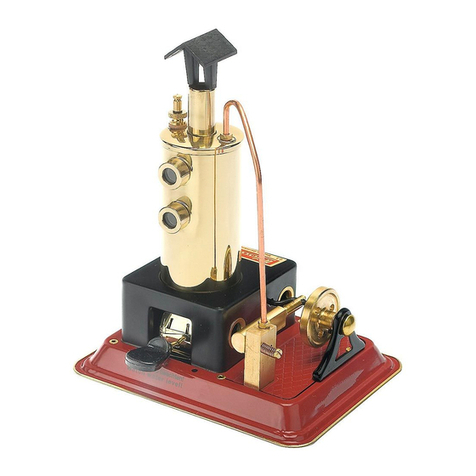
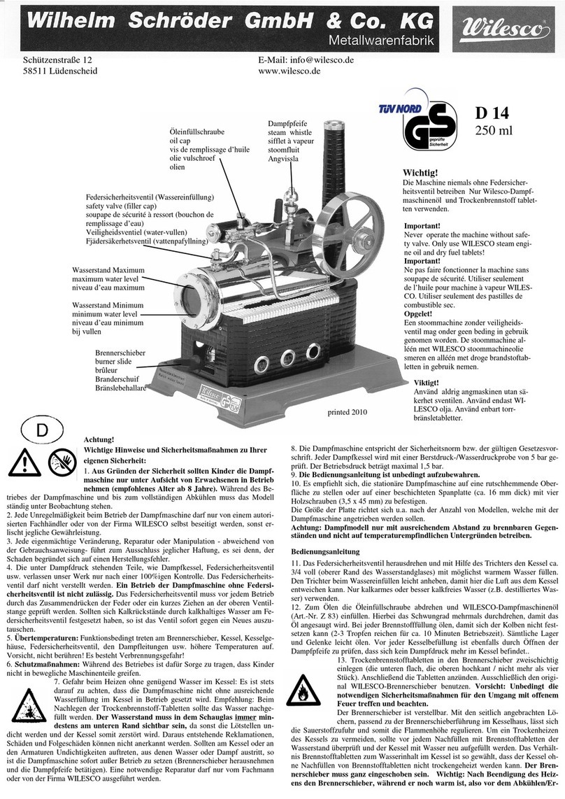
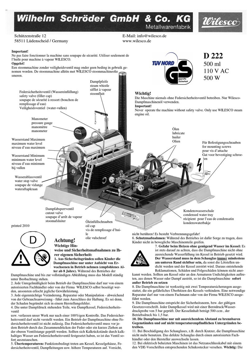
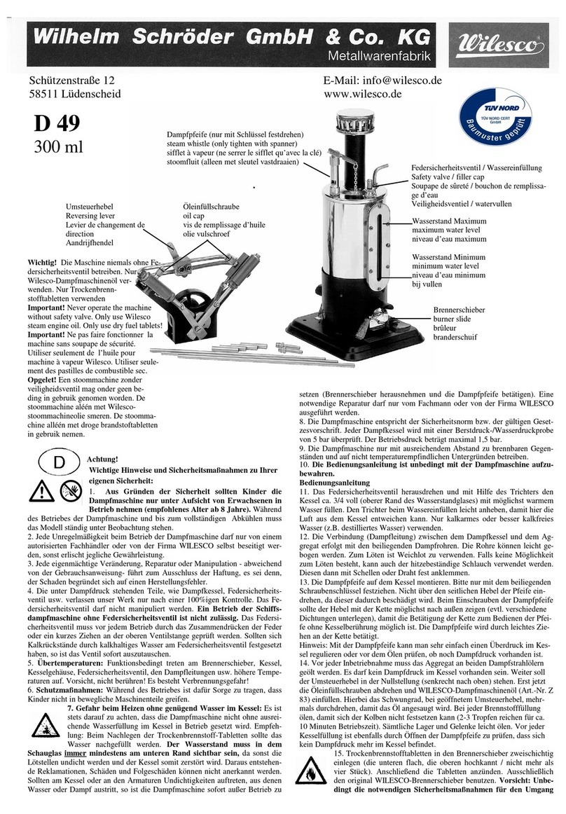
Wilesco D100E User manual

1
A
b
b.
2.
2.
1:
M
o
nt
a
g
e
d
es
K
es
se
ls
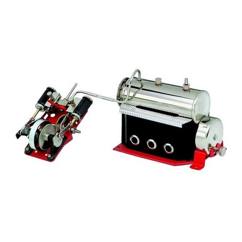
Steambox D 100 E
E-Box E 50

2

3
Steambox D 100E and E-Box E50
Wilhelm Schröder GmbH & Co. KG
D-58511 LÜDENSCHEID Schützenstraße 12
phone : +49 - 2351 - 9847-0 e-mail : info@wilesco.de

4
Important information:
Please read the instructions carefully before using the product. There you
find important information for a successful use.
Any damages caused by not following the instructions or the safety advices
will not be treated as guarantee cases!
We do not take any responsibility in case of following up damages!
All the information has been worked out with great care. On the other hand
one cannot exclude that mistakes may happen. We kindly advise you that
neither Wilesco nor the author will take any guarantee cases, juristically
responsibilities or assume any kind of liability as consequences of wrong
instructions or experiments.
Wilesco invites to send comments about possible mistakes via mail.
A symbol in a triangle is indicating a possible dangerous
situation, which needs more caution and attention.
Imprint:
This is a publication from Wilesco©, Wilhelm Schröder GmbH & Co KG, D-58511
LÜDENSCHEID. All rights including translation are reserved. Any reproduction, f. ex. photo
copies, microfilming, electronic data processing need a written permission of the author. Prints,
also only parts, are forbidden.
This publication has the technical update at moment of print. Changes of technical nature and
equipment are reserved.
© Copyright 2012 by Wilesco, Wilhelm Schröder GmbH & Co. KG
Dampfbox D 100E: EAN 4009807051013
E-Box 50: EAN 4009807012502
Set: Dipl. Ing. Thomas Schröder, Ulrich Stempel
Author: Ulrich Stempel
Translation: Ulrike Krampen
Wilhelm Schröder GmbH & Co. KG
D-58511 LÜDENSCHEID Schützenstraße 12
Telefone : 0049 - 2351 - 9847-0 Fax : 0049-2351-9847-47
e-mail : info@wilesco.de

5
Preface:
With this Steam Box or the E–Box 50 in combination with a steam engine
model and the booklet one can experience practically how the steam engine
and the transformation into electricity functions. Wilesco has joined for you
all the needed components in the Steam Box D 100E and the E-Box 50.
You are the owner of the Steam Box D 100E and now you build step by
step your own steam engine as a model. Through joining the different parts
one gets aware of the developed concept and the principle of the steam
engine, which has been invented by Denis Papin, James Watt and others.
This model does not only help to understand how a steam engine works, it
also creates a lot of joy to develop it even further.
With the Steam Box and the E-Box 50 and its components you can
practically experience and understand the transforming processes,
beginning with the thermo energy, through the mechanical energy and
finally turned into electrical energy. The experiments are structured and
build up one on the other. They are easy and in short time to realize.
In the booklet you also find information about the modern standard of the
steam engine and examples and possibilities of developments in the present
time.
I also would like to bring you this beautiful hobby of steam engine model
construction a little closer and wish you a lot of fun building this and other
steam engine models and the experiences you gain with it.
Yours
Ulrich Stempel

6

7
Inhaltsverzeichnis
1. BASICS ABOUT THE STEAM ENGINE........................................... 9
1.1 THE STEAM ENGINE AND ITS DEVELOPMENT....................... 9
1.2 KNOWLEDGE ABOUT THE STEAM ENGINE........................... 10
1.2.1 How to change water into steam .............................................. 10
1.2.2 The boiler.................................................................................. 11
1.2.3 The flywheel.............................................................................. 11
1.2.4 The oscillating steam engine .................................................... 11
1.2.5 The valve-controlled steam engine........................................... 13
1.3 POWER AN EFFICIENCY ............................................................. 14
1.3.1 Comparison: oscillating and valve-controlled steam engine... 14
1.4 WHAT FUNCTION HAS THE STEAM ENGINE NOWADAYS.15
1.4.1 Hybrid systems consisting photovoltaic constructions and the
steam engine ...................................................................................... 15
2. ASSEMBLING THE MODEL............................................................. 17
2.1 TRICKS AND TIPS FOR A SUCCESFUL ASSEMBLING ........ 17
2.2 ASSEMBLY INSTRUCTIONS STEP BY STEP............................ 18
Step 1: Assembly of the boiler ........................................................... 18
Step 2: Mounting the burner slide and boiler house......................... 18
Step 3: Assembling and mounting the flywheel................................. 19
Step 4: Assembling the cylinder unit ................................................. 20
Step 5: Mounting the steam pipe, chimney and final assembly......... 21
2.3 PRECAUTION INSTRUCTIONS................................................... 23
2.4 PREPARATION FOR THE FIRST TEST RUN............................. 25
3. EXPERIMENTS WITH THE STEAM ENGINE AND
ADDITIONAL COMPONENTS............................................................. 29
3.1 THE COMPONENTS AND THEIR DESCRIPTION..................... 29
3.1.1 The Generator........................................................................... 29
3.1.2 Transmission belt...................................................................... 30
3.1.3 The bread board ....................................................................... 31
3.1.5 LEDs......................................................................................... 33
3.1.6 Electrolytic (Electrolytic capacitors) ....................................... 34
3.1.7 Diode ........................................................................................ 36
3.1.8 Resistors.................................................................................... 37
3.1.9 Crocodile clips (red/black)....................................................... 38
3.1.10 Hook-up wire (red/black) ....................................................... 38
3.1.11 Switch...................................................................................... 39

8
3.2 FROM THE MECHANIC ENERGY TO THE ELECTRIC
ENERGY................................................................................................ 41
3.2.1 Connection and function of the current machine ..................... 41
3.3 FIRST EXPERIMENTS WITH THE GENERATOR ..................... 42
3.4 ROTATION DIRECTION INDICATOR........................................ 43
3.4.1 The transfer of the circuit......................................................... 43
3.4.2 The technical and the real current direction............................ 46
3.5 MOUNTING THE GENERATOR .................................................. 47
3.5.1 Generator, to connect mechanically with the flywheel of the
steam engine ..................................................................................... 48
3.5.2 Measuring the voltage of the generator ................................... 49
3.5.3 The direction of the rotation of the steam engine and the
generator ........................................................................................... 51
3.6 USING STEAM ENERGY TO GENERATE ELECTRICITY....... 52
3.6.1 Evaluating the power of the steam engine and of the
generator ........................................................................................... 52
3.7 STEP BY STEP GENERATING BRIGHT LIGHT OUT OF
STEAM .................................................................................................. 55
3.7.1 More light with 2 white LEDs................................................... 58
3.7.2 Light from four LEDs generated throught the steam engine.... 59
3.8 STORAGE OF THE ELECTRIC ENERGY.................................... 61
3.8.1 Charging the capacitor storage through the steam engine...... 61
3.8.2 Diode blocking discharge, Schottkydiode ................................ 64
3.8.3 Charge indicator for the electrolytic........................................ 66
3.8.4 Using stored energy.................................................................. 69
3.8.5 The steam engine as a charging station for the torch .............. 70
4. ANNEX................................................................................................... 73
4.1 COLLECTION OF THE FORMULARIES..................................... 73
4.1.1 Voltage, current and resistance................................................ 73
4.1.2 Parallel circuit of resistors....................................................... 74
4.1.3 Series connection of resistors................................................... 75
4.1.4 Calculation of the power .......................................................... 75
4.2 TROUBLESHOOTING................................................................... 75
4.2.1 The steam engine ...................................................................... 76
4.2.2 The electronic........................................................................... 76
4.3 SUPPLIER SOURCES FOR SPARE PARTS AND ELECTRONIC
PARTS.................................................................................................... 77
4.3.1 Consumable supplies for steam engines................................... 77
4.4 WARRANTY................................................................................... 78
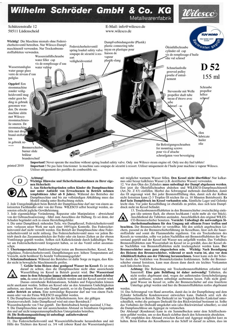
9
1. Basics about the steam engine
Steam engines are heat engines and they work in contrary to the combustion
motors without inner combustion. Mechanical energy is provided through
the pressure of the steam. One can use different sources of heat to make the
engine work; so all liquid, solid and gaseous fuels. Steam engines are also
capable to transform solar energy and growing fuels for our needs. They do
this in a low emission and climate neutral way.
1.1 The steam engine and its development
Constructions and their precursors, which work with steam pressure, have
been already used in the Greece antique. It is described that the doors of the
temple after lightening the holy fire would open in a magic way due to a
construction which worked with steam.
Leading steps in the development of the steam engine principles happened
during the time of the industrial revolution, f. ex. through Denis Papin. 1690
he invented the pressure cooker, where he developed a first prototype of a
steam engine with cylinder and piston. In 1698 the British engineer Thomas
Savery constructed an engine, working on steam, which was supposed to
pump the groundwater. In 1712 the engineer Thomas Newcomen developed
the principle even further into an atmospheric steam engine.
Information:
The atmospheric steam engine is a precursor model with the following
function: water steam is pressed into the space of the cylinder below the
piston, which cools down through added cold water and finally condenses.
This causes a negative pressure and because of the higher external
atmospheric pressure now the piston is pressed into the cylinder. Through
the flywheel mass and the opened steam valve the piston is again pressed
into the cylinder. The energetic efficiency of this construction is about
1%.
In 1769 James Watt managed to patent a double functioning steam engine.
In this construction the piston is alternately shifted from one side to the
other through steam. This increased the efficiency enormously. James Watt
described the out put of his engine in horsepower, which had been used as a
measurement for power engines for a long period of time, f. ex. with
automobiles.

10
At that time the steam engine brought a lot of possibilities in the areas of
transport and construction. From the first rotation on the engine brings a
high torque to the axis and is able to work forwards and backwards. Steam
automobiles can start moving under load and do not need clutch and
gearing.
1.2 Knowledge about the steam engine
Right behind the wind power the steam power is one of the ancient methods
of humankind to produce mechanical energy. The name steam engine is
already indicating the energy source; steam. The energy source steam was
and is transformed into other energy forms through different constructions,
f. ex. piston steam engine or steam - turbines.
Basically we need two components regarding to the principle of the steam
energy: the steam boiler and the piston steam engine or the steam –turbine.
This principle has not changed till nowadays. Still changes have happened
within the modern steam engine regarding to the technical designs, modern
materials and a profound knowledge how to increase the efficiency.
In earlier times the efficiency of the piston steam engine was very low.
Especially to generate electricity they were mainly substituted through
steam turbines, which worked more efficiently. Nowadays functioning
nuclear power bases are so to speak modern steam engines, working with
the same principle. Here one uses the problematic nuclear energy to heat up
the water.
1.2.1. How to change water into steam
To transform the liquid state of H2O into water steam, we need to heat it up
till it boils. Once the water is boiling, which normally happens at 100
degrees C and 1013 hPa (the boiling temperature depends on the altitude of
the place, more exact - on the external air pressure) it changes into steam.
The boiling temperature of water (in general with liquids) changes when the
external air pressure raise. Assuming we have 2 bar pressure in the steam
boiler the boiling temperature raises up to 120 degrees C (theoretical value).
The heating up needs a certain quantity of energy which is called heat of
evaporation. There are needed 4,2 joule to heat up 1 gram of water for 1
degree C. On the other hand it needs 2257 joule to evaporate 1 gram of
water. This high energy consumption can be explained through the
enormous expansion of the volume of the water steam in relation to its
liquid state.1 litre of boiling water will transform into 1673 litres of steam
(these values are related to normal air pressure).

11
Keeping the arising steam in a closed vessel will produce a very high
pressure, which can even lead to an explosion of the boiler.
Therefore the steam engines have safety valves which open with high
pressure so the steam can escape.
One uses the pressure of the steam by moving a piston in a cylinder, which
produces mechanical energy.
Information:
In physics we use the parameter “p”for pressure, which acts with a power
“F”on a surface “A”.
When the steam cools down a contrary process is taking place, the steam
condenses. Now the energy which has been used to evaporate is set free.
Water steam condenses f. ex. on colder metals and is then visible in little
water drops.
1.2.2 The boiler
There are different designs of the steam boiler depending on the use and
form of the steam engine. The main intension is to provide constantly
enough steam so that the pistons of the steam engine are moving.
1.2.3 The flywheel
The steam engine transforms the back- and forward movement into a
rotating movement.
The classical steam engine has a heavy flywheel to provide an even
rotation. This helps to overcome the upper and lower dead centres. The
flywheel is an energy storage, which stores the energy of the “power
strokes”and therefore bridges the passive time.
1.2.4 The oscillating steam engine
With the help of the oscillating principle one easily can realize a
functioning steam engine model. The oscillating steam engine regulates the
in and outlet of the steam through the moving cylinders. Constructions of
centred rotatable bearings provide the needed flexibility of the cylinder.
Through a coil spring the cylinder is compressed against the holder. The
sliding surfaces need to be even.

12
Fig. 1.01: The oscillating cylinder:
steam engine model of the steam box
On the back of the cylinder we find a hole which is called steam hole. On
the connected surface of the fixing bracket we find a steam supplying hole
and a steam exhausting hole. Steam enters into the cylinder when the steam
hole of the cylinder is exactly positioned on top of the steam supplying
hole. The piston moves out of the cylinder and the lifting movement is
transformed into a rotating movement through the rod bearing and the crank
(eccentric bearing). The flywheel mass leads the piston back so that the
cylinder is tipping backwards with its steam hole on top of the steam
exhausting hole and the used steam escapes. When the piston has overcome
the rear dead centre the steam hole moves again on top of the steam
supplying hole, steam enters the cylinder again and the explained process
repeats itself.
The principle of the oscillating steam engine
The water steam provided by the boiler enters through the steam sup-
plying hole into the cylinder and presses the piston out of the cylin-
der. Through the crank movement the cylinder moves on and the
steam inlet is closed.
Through the uplifting movement of the piston the cylinder moves on
and reaches the steam exhausting hole. The cooled water steam is
pressed out and escapes to the sides. The process starts again.
The advantage of this type of engine is a much easier construction. It is a
complete and powerful engine and was used in steam navigation.

13
1.2.5 The valve–controlled steam engine
Contrary to these simple constructions there are also valve-controlled
models available, such as the steam engine model D9/D10, D20 and other
models from Wilesco.
The valve-controlled steam engine works like this:
Water steam provided by the boiler enters the slide box and a slider presses
on one side of the piston within the cylinder. The high pressure steam
pushes the piston into the cylinder. As the piston is connected with the
crankshaft through a connecting rod the flywheel now turns on half a
rotation. Now the slider is moved. The steam feed happens now on the other
side of the piston, which is then pressed backward through the steam.
The cooled steam leaves through the steam outlet, f. ex. through the
chimney of the steam engine model. The process starts again.
Fig.1.02
The principle of the valve-controlled steam engine (a cut through cylinder
and slider) a) steam presses the piston (1) to the right, b) to the left. 1=
piston, 2= cylinder, 3= slider rod, 4= slider box, 5= steam outlet, 6= steam
inlet
The steam engine can consist out of one or several cylinders. The advantage
of several cylinders is a continuous power transfer.

14
1.3 Power and efficiency
One of the real advantages of the steam engine is that through the external
combustion he does not depend on high quality fuel. He works with any
kind of fuel, f. ex. coal, wood, oil, peat, any kind of waste etc. This is not
true for the steam engine model, they are fed with dry spirit tablets. Another
advantage of the steam engine is that they produce relatively little operating
noise. What one can hear is the noise of the mechanics and the exhaustion
of the steam, the engine itself runs almost silent.On the other hand we have
a very essential disadvantage. The steam engine has a very low efficiency;
only 10 to 12%, which means only 12% of the involved energy of the fuel is
transformed into kinetic energy.
1.3.1 Comparison: oscillating and valve-controlled steam
engine
With the model Steam Box and the model D20 one can explore easily the
difference between the oscillating and the valve-controlled steam engine.
Also with the experiments of the Steam Box one can point out the
differences very clearly.
Fig.1.03 on the left side the steam engine model of the Steam Box with the
oscillating cylinder, to the right the model D20 (valve-controlled).

15
Beside the different technical structures both models also differ in power
transfer and efficiency. For the same amount of power the Steam Box
model needs more fuel then the D 20 model. The generator is excellent to
explore the power transfer.
1.4 What function has the steam engine nowadays?
In the area of the power engines the steam engine was substituted through
the combustion engine. Because of the high energy content of the fuel (10-
12 kWh per litre) one gains a higher efficiency together with less weight
and more comfortable operation. Today there are still areas of use for the
steam engine. These constructions are used in the coal mining and conveyor
belts. Here the steam engine works as well as a winding machine for coal
and at the same time as a brake to let down filling material. The kinetic
energy which is produced through the letting down movement is used to
heat up the steam.
Now and again there are engineers who pick up the principle of the steam
engine and bring it into the world with modern materials. One advantage to
the combustion engine is the external combustion process and the use of a
variety of fuels. Another one is the overload capacity of the steam engine.
Overload capacity means that the nominal value and the continuous power
transfer can be shortly and without problems exceeded. One can prove this
in the described experiments, f. ex. by short-circuiting the generator.
Modern steam engines with low emission combustion produce steam
efficiently and then similar like a diesel engine they inject the steam
through nozzles. Those engines work in the 2-stroke process and do not
need common lubricants, because the mechanical parts are made out of
carbonic components.
1.4.1 Hybrid systems consisting photovoltaic constructions and
the steam engine
There exist different explorations and examinations regarding to hybrid
systems consisting modern photovoltaic in combination with modern
concepts of the steam engine.
These combined systems make sense in climate regions where solar energy
mainly is used in the summer season and a complement is needed for the

16
winter season. A combined heat and power production serves well, mainly
for the heating season. Systems like this provide f. ex. for private
households or internal consumers, an all year round and energy self-
sufficient concept.
Instead of the steam engine one also can use a Stirling engine. Both
constructions can work with all kinds of solid and liquid fuels, f. ex. wood,
coal, biogas etc.
Information: If you work with the E-Box 50 or a different model you can
skip this chapter (2) and move on to the next (3) and continue to
experiment with the steam engine model you have.

17
2. Assembling the model
Depending whether you work with the Steam Box D100 E or you already
have a fixed model this chapter continues with putting together the steam
engine model. The following chapter shows experiments with an already
existent steam engine model.
2.1 Tricks and tips for a successful assembling
Sometimes it seems a little difficult to screw in some screws in an
inaccessible positions, like in the area of the flywheel. It is very useful to fix
a little magnet on the screwdriver so that it becomes magnetised. Now the
screw can easily be lead to the prepared drilled hole.
Fig.2.01:
Screwdriver becomes
magnetised and holds the
screw.
To tighten the screw properly it makes sense to use the screwdriver on the
one side and on the other side hold the screw-nut with a spanner.
It is helpful to put all the small pieces like screws, nuts and seals into a flat
container so they do not get lost.
How to lubricate the moving parts:
A good service brings a small disposable syringe, with a blunt needle (the
peak of the needle can be cut of or grinded down). This allows injecting the
steam engine oil well measured onto the oil needing parts.
Do not use any liquid oil for lubricating the piston and cylinder. Please
only use Wilesco steam engine oil.

18
Fig. 2.02: Lubricating with a disposable syringe
Before lightening the dry spirit tablets check whether the burner slide
moves easily in and out of the burner slide box (in the boiler house of the
steam engine model). If not you can slightly widen the sides of the burner
slide box.
2.2 Assembly instructions step by step
All the parts that you require to build this steam engine, including the tools,
are contained in the Steam Box D 100E. The instruction leaflet is divided
into assembling steps, and each step is illustrated.
Please follow the instructions exactly and step by step, so that the operation
of the steam engine is successful.
Step 1: Assembly of the boiler
Insert the fixing bracket of the boiler through the boiler house (2) from
beneath until the angled sides fit against the upper flanges of the boiler
house (2). Locate in the centre notches to restrict sideways movement, now
the bracket will stay in place due to its own tension. Push the boiler (3)
according to the Fig. 2.2.1 (The water level glass has to stay on the side of
the fire place) between the fixing bracket (4) and the boiler house. Now
push the boiler up against the bracket, and at the same time slide it forwards
until it locks on the rear boiler support.
Fig. 2.2.1: mounting the boiler

19
Step 2: Mounting the burner slide and boiler house
CAUTION work carefully because of sharp edges! Insert the tabs on the
burner slide (5) with the point facing towards the front into the
corresponding slots on the base plate (1). Turn the base plate (1) over, and
tap the burner slide tabs outwards, using the screwdriver handle. This is best
done by resting the burner slide on the edge of a table.
Now insert the long tab on the boiler house into the long slot in the base
plate (1), locate the remaining two tabs into the corresponding slots and tap
these over as well. This is best achieved by resting the chimney vent on the
edge of the table. Attach the stickers “watch water level”on the base plate
(1) under the water level glass and the sticker of the model number next to
it.
Fig.2.2.2: mounting the burner slide and the boiler house
Step 3: Assembling and mounting the flywheel.
On the short side of the flywheel axle (8) fit one bearing frame (7) and then
screw on the crank plate (12). On the other side of the axle slide onto in the
following order the distance bush (9), the second bearing frame (7) and 1
washer (11), then screw on the pulley wheel (10) again. Now tighten the
crank plate (12) and the pulley wheel (10) against each other. This flywheel
unit is now fixed onto the base plate (1) using the screws M3x6 (24) and the
nuts (25) so that the crank plate faces towards the outside.
To mount this part is a little difficult, so please look under tricks and tips
using the idea with the magnet on the screwdriver.

20
Fig.2.2.3: mounting the flywheel
Step 4: Assembling the cylinder unit.
Mount the cylinder unit first by fitting the spring (18) and the baffle plate
(15) onto the screw M3x16 (17). Now tighten her into the threaded hole on
the cylinder (20) by turning the screw only 1-2 times. Do not turn further
otherwise this will damage the cylinder. Now fit the baffle plate and the
condensed water tray to the base plate using two screws (24) and nuts (25).
Insert the screws from underneath the base plate.
Fig.2.2.4 mounting
the cylinder unit
This manual suits for next models
1
Table of contents
Other Wilesco Engine manuals

Wilesco
Wilesco D 222 User manual

Wilesco
Wilesco D 48 User manual

Wilesco
Wilesco D 12 User manual

Wilesco
Wilesco D305 User manual

Wilesco
Wilesco D21 User manual

Wilesco
Wilesco D 24 User manual

Wilesco
Wilesco D15 User manual

Wilesco
Wilesco D 49 User manual

Wilesco
Wilesco D 5 User manual

Wilesco
Wilesco D 52 User manual