Digga SG26 Product manual

PM-000033
4 Octal Street, Yatala QLD 4207 Australia
Ph: (07) 3807 3330 - Fax: (07) 3807 1499
Email: [email protected]
OPERATOR’S AND PARTS
MANUAL
SG26 & SG30
STUMP GRINDER
UNIVERSAL SKID STEER
APPLICATIONS


TABLE OF CONTENTS
TO THE OWNER........................................................................................................ A
SAFETY PRECAUTIONS............................................................................................B
General Information
To The Operator
Before You Start
Working With The Stump Grinder
Transporting The Stump Grinder
Maintenance
INTERNATIONAL SYMBOLS......................................................................................C
PREOPERATION........................................................................................................D
Before Operation
Skid Steer
Nomenclature
STUMP GRINDER ASSEMBLIES.............................................................................. E
Stump Grinder Assembly #100318
Rear Guard Assembly #101742
Wheel Assemblies
Hydraulic Valve Assembly #100982
Control Valve Replacement Parts
Standard Flow Drive Assembly #100415
High Flow Drive Assembly #100417
Power and Return Circuit
Cylinder Assembly #100324
Cylinder Assembly #101245
Electrical Schematics - Control Handles (#104367 - Direct & #104368 - use with #101096)
Electrical Schematics - Wiring Harness’s (#101096 - 14 Pin, #108035 - 8 Pin & #108036 - 14 Pin JD)
INSTALLATION INSTRUCTIONS................................................................................F
OPERATING INSTRUCTIONS...................................................................................G
LUBRICATION.............................................................................................................H
MAINTENANCE...........................................................................................................L
Daily / Every 40 Hours
Replacing Teeth
Replacing Hydraulic Motor
Replacing Gearbox / Motor Coupler
Replacing Gearbox
Cylinder Seal Replacement
STORAGE AND TRANSPORTING.............................................................................M
TROUBLESHOOTING................................................................................................N
BOLT TORQUE SPECIFICATION...............................................................................O
SPECIFICATIONS...................................................................................................... P
DECALS......................................................................................................................Q
PREDELIVERY CHECKLIST.......................................................................................R
LIMITED WARRANTY..................................................................................... ............S


TO THE OWNER
8915
3-5-03
A A
GENERAL COMMENTS
Congratulations on the purchase of your new DIGGA product! This
product was carefully designed and manufactured to give you years of dependable
service. Only minor maintenance (such as cleaning and lubricating) is required to
keep it in top working condition. Be sure to observe all safety precautions and
maintenance procedures, as described in this manual.
ABOUT THIS MANUAL
This manual has been designed to help you do a better, safer job. Read this
manual carefully and become familiar with its contents. Remember, never let
anyone operate this unit without reading the “Safety Precautions” and
“Operating Instructions” sections of this manual. (See Sections B and G
respectively.)
Unless noted otherwise, right and left sides are determined from the position
of the operator when behind the product facing forward.
SAFETY ALERT SYMBOL
This is the “Safety Alert Symbol” used by this industry. This symbol is
used to warn of possible injury. Be sure to read all warnings carefully.
They are included for your safety and for the safety of others working
with you.
SERVICE
When servicing your product, remember to use only manufacturer replacement
parts. Substitute parts may not meet the standards required for safe, dependable
operation.
To facilitate parts ordering, record the model and serial number of your unit in
the space provided on this page. This information may be obtained from the identication
plate located on the product.
MODEL____________________________________
SERIAL NUMBER___________________________
DATE PURCHASED_________________________
The parts department needs this information to insure that you receive the
correct parts for your specic model.


SAFETY PRECAUTIONS
6621
5-18-95
B B
TAKE NOTE! THIS SAFETY ALERT SYMBOL FOUND THROUGHOUT THIS MANUAL
IS USED TO CALL YOUR ATTENTION TO INSTRUCTIONS INVOLVING YOUR PER-
SONAL SAFETY OR OTHERS. FAILURE TO FOLLOW THESE INSTRUCTIONS CAN
RESULT IN INJURY OR DEATH.
THIS SYMBOL MEANS:
ATTENTION!
BECOME ALERT!
YOUR SAFETY IS INVOLVED!
SIGNAL WORDS: Note the use of signal words DANGER, WARNING, and
CAUTION with the safety messages. The appropriate signal word for each has
been selected using the following guidelines:
DANGER: Indicates an imminently hazardous situation, which if not avoided,
will result in death or serious injury. This signal word is to be limited
to the most extreme situations, typically for machine components
which, for functional purposes, cannot be guarded.
WARNING: Indicates a potentially hazardous situation, which if not avoided,
could result in death or serious injury, and includes hazards that
are exposed when guards are removed. It may also be used to
alert against unsafe practices.
CAUTION: Indicates a potentially hazardous situation, which if not avoided,
may result in minor or moderate injury. It may also be used to
alert against unsafe practices.

SAFETY PRECAUTIONS
9714
6-28-04
B B
GENERAL INFORMATION
This section is composed of various warnings and safety tips. Read and
learn all the information in this section before you attempt to use your DIGGA
STUMP GRINDER. Also read your vehicle owner’s manual before using your
equipment. This knowledge will help you operate your unit safely. Do not take
this information lightly, it is presented for your benet and for the benet of others
working around you.
The “Safety Alert Symbol” (as described in Section A and at the beginning
of Section B) will be used throughout this manual. It will appear with the word
DANGER, WARNING, or CAUTION above it, and a safety message pertaining to
the specic topic being covered. Take the time to read these messages as you
come across them.
TO THE OPERATOR
The primary responsibility for safety with the equipment falls to the operator.
Make sure that the equipment is operated only by responsible & competent
individuals with the proper instruction. It is the skill, care, common sense, and
good judgement of the operator that will determine how efciently and safely the
job is performed. Know your equipment before you start. Know its capabilities
dimensions, and how to operate all the controls. Visually inspect your equipment
before you start and never operate equipment that is not in proper working order.
BEFORE YOU START
1. Read the entire loader and Stump Grinder manual. This knowledge is necessary
for safe operation.
2. Do NOT operate the standard ow stump grinder on high ow hydraulic
systems. Severe injury could occur due to the increased RPM.
3. Always wear safety goggles and hearing protection during operation, and
make sure ALL safety shields are properly installed.
4. Follow all safety decals. Keep them clean and replace them if they become
worn, damaged or illegible.
5. Do not paint over, remove or deface any safety signs or warning decals on
your equipment.
6. Know your equipment inside and out. Know how to operate all controls
and know emergency shut down procedures.
7. Keep all stepping surfaces, pedals, and controls free from dirt, grease and
oil. Keep equipment clean to help avoid injury from a fall when getting on
or off equipment.
8. Use handholds and step plates when getting on/off . Failure to do so could
cause a fall.
DIGGA STUMP GRINDER

SAFETY PRECAUTIONS
9715
6-28-04
B B
DIGGA STUMP GRINDER
9. Never operate the unit near bystanders, trafc, pets, livestock or buildings.
Be sure others know when and where you will be working. Never
direct discharge towards people, animals or property. Never allow anyone
to approach the stump grinder when in operation.
10. Never take passengers on your equipment. There is no safe place for a
passenger.
11. Never try to board equipment while it is running.
12. Turn off engine, remove the key and disconnect hydraulic couplers
before performing maintenance. If unit must be left raised for maintenance
or any other reason, block the unit securely to prevent accidental
release of the lifting mechanism. Serious damage or personal injury
could result.
13. Never leave the unit unattended when in a raised position. Always make
sure the attachment is on the ground and keys removed before leaving
the unit unattended.
14. Test all controls before you begin.
15. Do not smoke when refueling. Allow room in the gas tank for expansion.
Wipe up any spilt fuel. Secure cap tightly when done.
WORKING WITH THE STUMP GRINDER
1. Never operate the unit without rst reading and understanding the
operator’s manual.
2. Operate the unit only in daylight or sufcient articial light.
3. Do not carry load with arms in the raised position. Always carry loads
as close as possible to the ground.
4. Check your work area and know where all utility lines are. Avoid hitting
underground electrical wires, cables, pipes, fence posts, gas lines,
uneven sidewalk edges, large rocks, etc.
5. Never operate equipment while under the inuence of alcohol, prescription
drugs, nonprescription drugs, or illegal drugs which could inhibit
physical and/or mental capacity.
6. Do not exceed rated operating capacity, as machine may become unstable
which may result in loss of control.
7. Do not operate the unit without covers installed.
8. Keep hands, feet, hair and clothing away from equipment with engine
running. Stay clear of all moving parts.
9. Do not raise the attachment when the grinding wheel is rotating.
10. ALWAYS LOWER THE LOADER ARMS TO THE GROUND, SHUT OFF
THE ENGINE AND REMOVE THE KEY BEFORE GETTING OFF THE UNIT.
SAFETY PRECAUTIONS
9716
6-28-04
B B
DIGGA STUMP GRINDER
TRANSPORTING THE STUMP GRINDER
1. Follow all federal, state and local regulations when transporting the unit on
public roads.
2. Use extra care when loading or unloading the machine onto a truck or
trailer. Disconnect hydraulic couplers during transportation.
MAINTENANCE
1. Never work on equipment while it is running. Always lower the loader arms
to the ground, shut off the engine, remove the key and disconnect
hydraulic couplers before performing maintenance on the unit.
2. Never make hydraulic repairs while the system is under pressure. Injury or
death could result.
3. Observe proper maintenance schedules and repairs to keep the unit in safe
working order.
4 Always wear safety goggles or glasses when working on equipment.
5. Use only manufacturer recommended replacement parts. Other parts may be
substandard in t and quality.
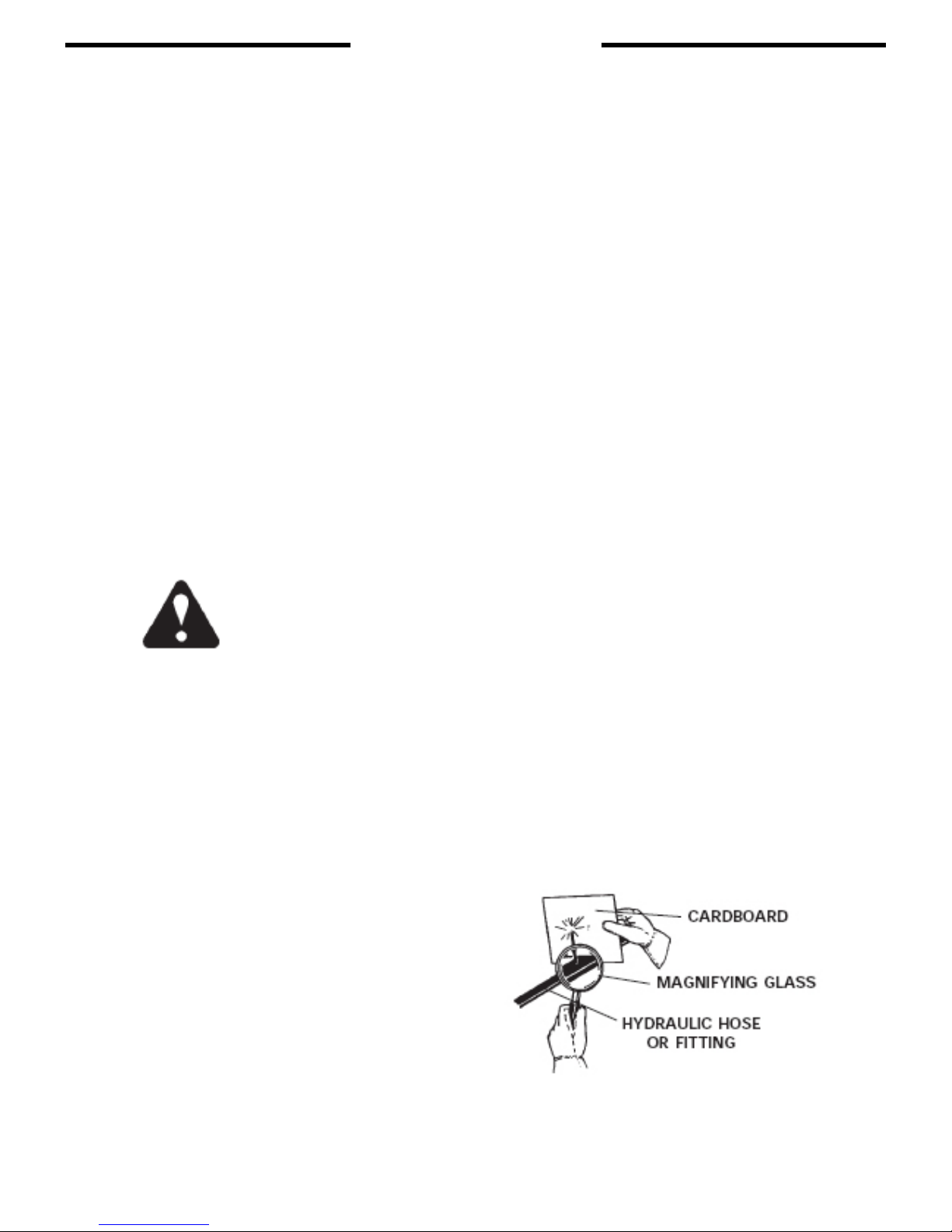
WARNING! Escaping uid under pressure can have sufcient force to penetrate
the skin causing serious personal injury. Fluid escaping from a very
small hole can be almost invisible. Use a piece of cardboard or
wood, rather that hands to search for suspected leaks.
Keep unprotected body parts, such as face, eyes, and arms as far
away as possible from a suspected leak. Flesh injected with hydraulic
uid may develop gangrene or other permanent disabilities.
If injured by injected uid, see a doctor at once. If your doctor is
not familiar with this type of injury, ask him to research it immediately
to determine proper treatment.

INTERNATIONAL SYMBOLS
3869
4-14-94-2
C C
As a guide to the operation of your equipment, various international symbols have
been utilized on the instruments and controls. The symbols are shown below with an indi-
cation of their meaning.

PREOPERATION
9762
8-6-04
D D
DIGGA STUMP GRINDER
GENERAL INFORMATION
The DIGGA Stump Grinders were designed to be easy to use and
maintain. They are operated by the skid-steer auxiliary hydraulics and mount to
the quick attach mechanism for easy operator hook-up. There are two models of
DIGGA stump grinders available, standard ow and high ow. These will allow
mounting the stump grinder to most skid-steer loaders.
Unless noted otherwise, right and left are determined from the position of
the skid-steer operator sitting in the operator’s seat facing forward.
Remember to read the “Safety Precautions” and “Operating Instructions”
sections of the manual BEFORE you attempt to install or use the Stump Grinder
.
NOTE: Illustrations and data used in this manual were current (according to
the information available to us) at the time of printing, however, we reserve
the right to redesign and change the grinders as may be necessary without
notication.
BEFORE OPERATION
The primary responsibility for safety with this equipment falls to the operator.
Make sure that the equipment is operated only by trained individuals that
have read and understand this manual. Don’t hurry the learning process or take
the unit for granted. Practice the operation of your new equipment and become
familiar with the controls and the way it handles on your machine.
If there is any portion of this manual or function you do not understand,
contact your local authorized dealer or manufacturer.
SKID-STEER
Your skid-steer must be equipped with auxiliary hydraulic and an electric
control kit (or the optional electric control handle must be ordered from your
DIGGA dealer).
There are two models of DIGGA stump grinders available, standard
ow and high ow. Be sure the stump grinder you have purchased matches the
hydraulic ow of your skid-steer.
The standard ow unit requires 15-22 GPM and the high ow requires 25-
42 GPM. Operating the high ow stump grinder on a standard ow skid-steer will
result in poor performance.
WARNING! OPERATING THE STANDARD FLOW STUMP GRINDER ON A
HIGH FLOW HYDRAULIC SYSTEM MAY CAUSE SEVERE INJURY
OR DEATH TO THE OPERATOR OR BYSTANDERS DUE
TO THE INCREASED RPM.
PREOPERATION
9763
8-6-04
D D
DIGGA STUMP GRINDER
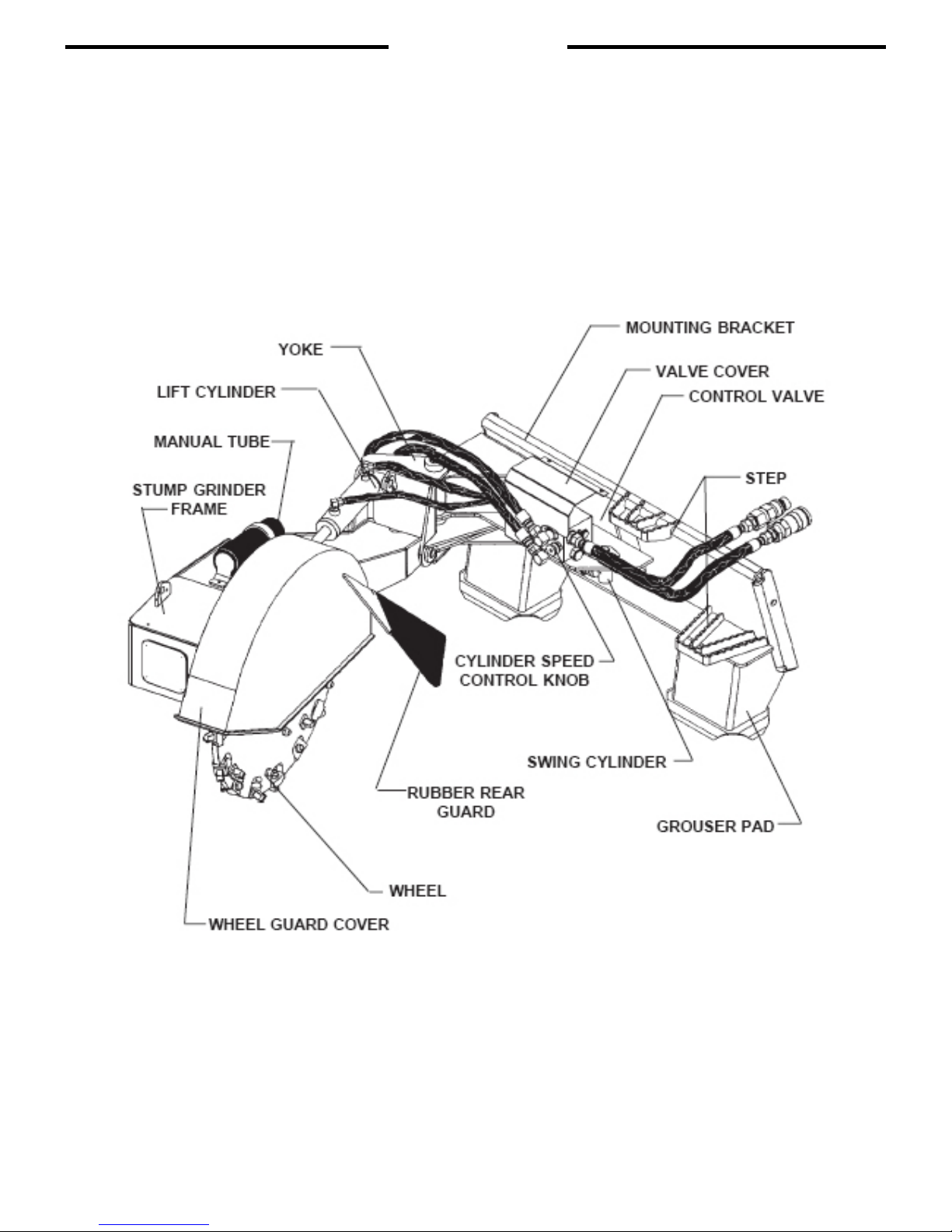
NOMENCLATURE
Throughout this manual, reference is made to various stump grinder
components. The purpose of this page is to acquaint you with the various names
of these components. This knowledge will be helpful when reading through this
manual or when ordering service parts.
STUMP GRINDER ASSEMBLY
9693
1-30-07-2
E E
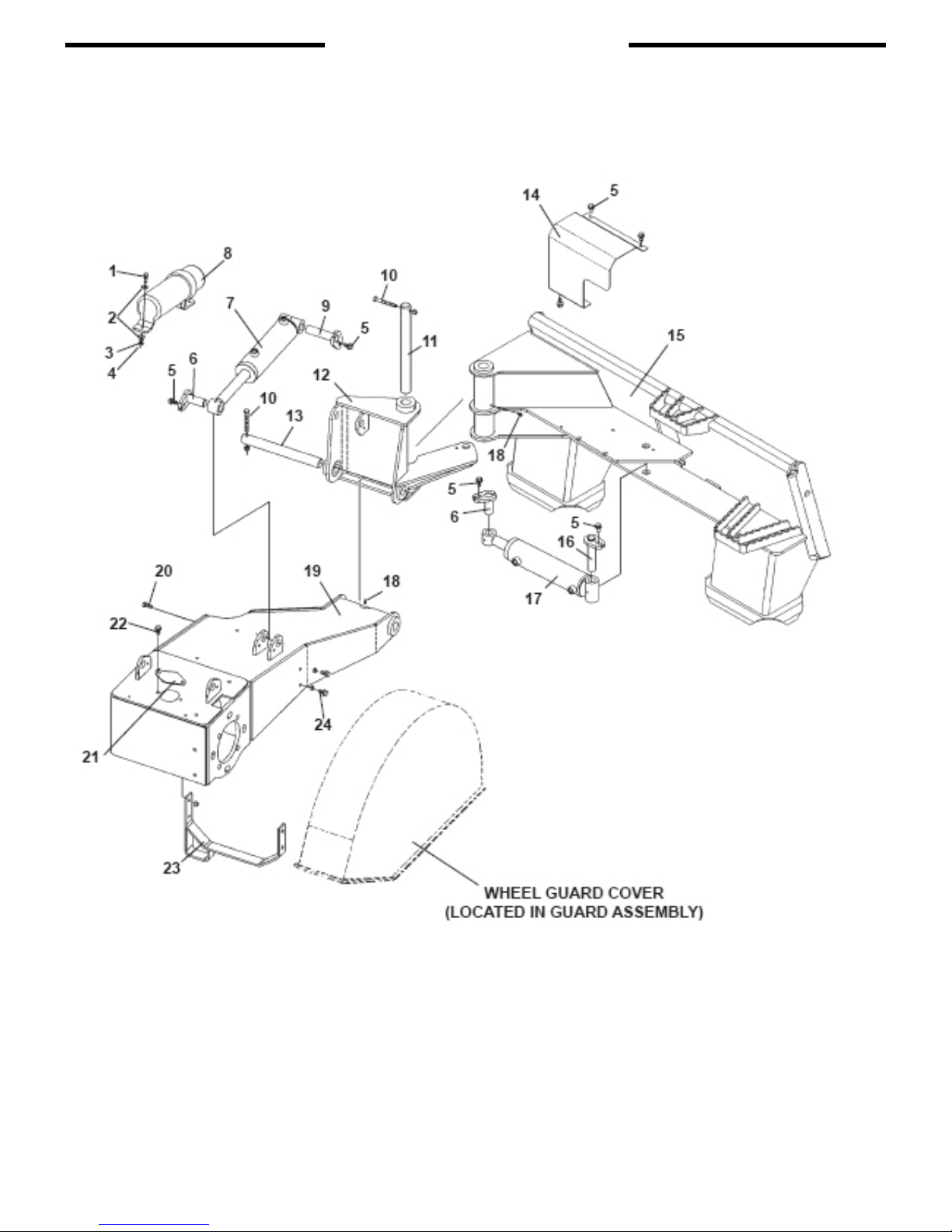
ASSEMBLY #100318

STUMP GRINDER ASSEMBLY
9383
1-31-07-2
E E
ASSEMBLY #100318
NO REQ’D PART NO. DESCRIPTION
1 2 1022 .31” UNC X 1.00” Hex Capscrew
2 4 1513 .31” Flat Washer
3 2 1502 .31” Lock Washer
4 2 1225 .31” UNC Hex Nut
5 7 1953 .38” UNC X .75” Flange Head Capscrew
6 2 100769 Pin - 1.00” X 2.50”
7 1 101245 Cylinder Assembly - Lift
- 45617 Replacement Seal Kit
8 1 25453 Manual Tube
9 1 100770 Pin - 1.00” X 4.00”
10 2 1051 .38” UNC X 3.00” Hex Capscrew
2 1837 .38” UNC Deformed Lock Nut
11 1 100379 Pin - 1.25” X 13.50”
12 1 100322 Yoke
13 1 100378 Pin - 1.25” X 11.38”
14 1 100420 Valve Cover
15 1 100321 Mounting Bracket
16 1 31990 Pin - 1.00” X 4.50”
17 1 100324 Cylinder Assembly - Swing
- 45617 Replacement Seal Kit
18 2 6616 Grease Fitting
19 1 100323 Stump Grinder Frame
20 2 1043 .38” UNC X 1.00” Hex Capscrew
2 1837 . 38” UNC Deformed Lock Nut
21 1 105762 Access Cover
22 2 1939 .25” UNC X .75” Flangehead Hex Capscrew
23 1 101802 Brace Stand
24 2 1044 .38” UNC X 1.25” Hex Capscrew
2 1837 .38” UNC Deformed Lock Nut

REAR GUARD ASSEMBLY
9765
1-30-07-2
E E
ASSEMBLY #101742

REAR GUARD ASSEMBLY
9383
1-31-07-2
E E
ASSEMBLY #101742
NO REQ’D PART NO. DESCRIPTION
1 1 102061 Wheel Guard Cover
2 4 1043 .38” UNC X 1.00” Hex Capscrew
3 10 1837 .38” UNC Deformed Oval Lock Nut
4 1 102062 Rear Rubber Guard Bracket
5 1 100802 Rubber Guard
6 2 1049 .38” UNC X 2.50” Hex Capscrew
7 20 1514 .38” Flat Washer
8 8 1044 .38” UNC X 1.25” Hex Capscrew
SQUARE TOOTH WHEEL ASSEMBLY
9766
8-9-04
E E
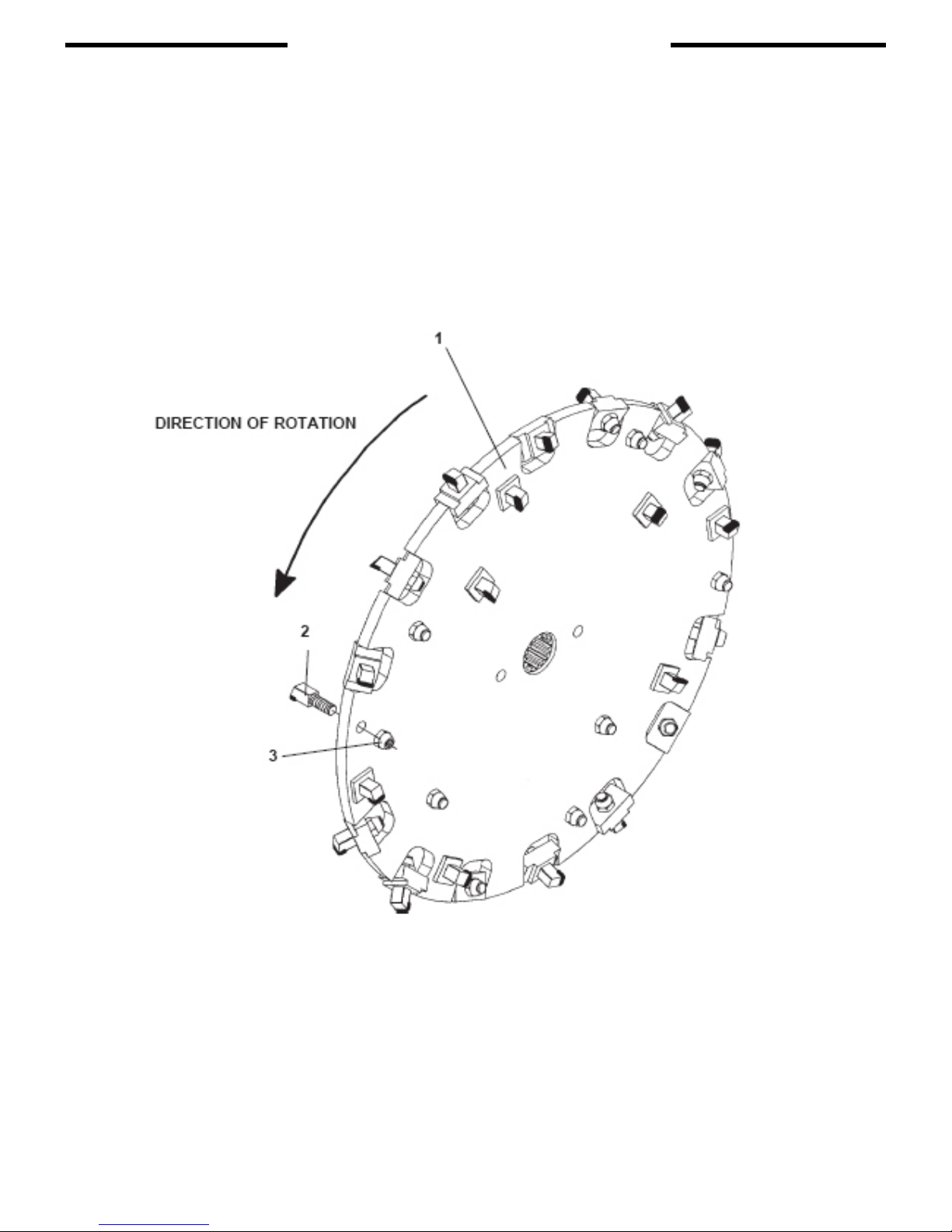
26” STANDARD FLOW WHEEL ASSEMBLY #101234
30” HIGH FLOW WHEEL ASSEMBLY #100418

SQUARE TOOTH WHEEL ASSEMBLY
9767
8-9-04
E E
26” STANDARD FLOW WHEEL ASSEMBLY #101234
30” HIGH FLOW WHEEL ASSEMBLY #100418
NO REQ’D PART NO. DESCRIPTION
1 1 101235 26” Wheel - Standard Flow
1 19911 30” Wheel - High Flow
2 28 19917 Square Tooth - Threaded
3 28 1810 .62” UNF Deformed Lock Nut
REPLACEMENT TOOTH KIT #102075
28 19917 Square Tooth - Threaded
28 1810 .62” UNF Deformed Lock Nut
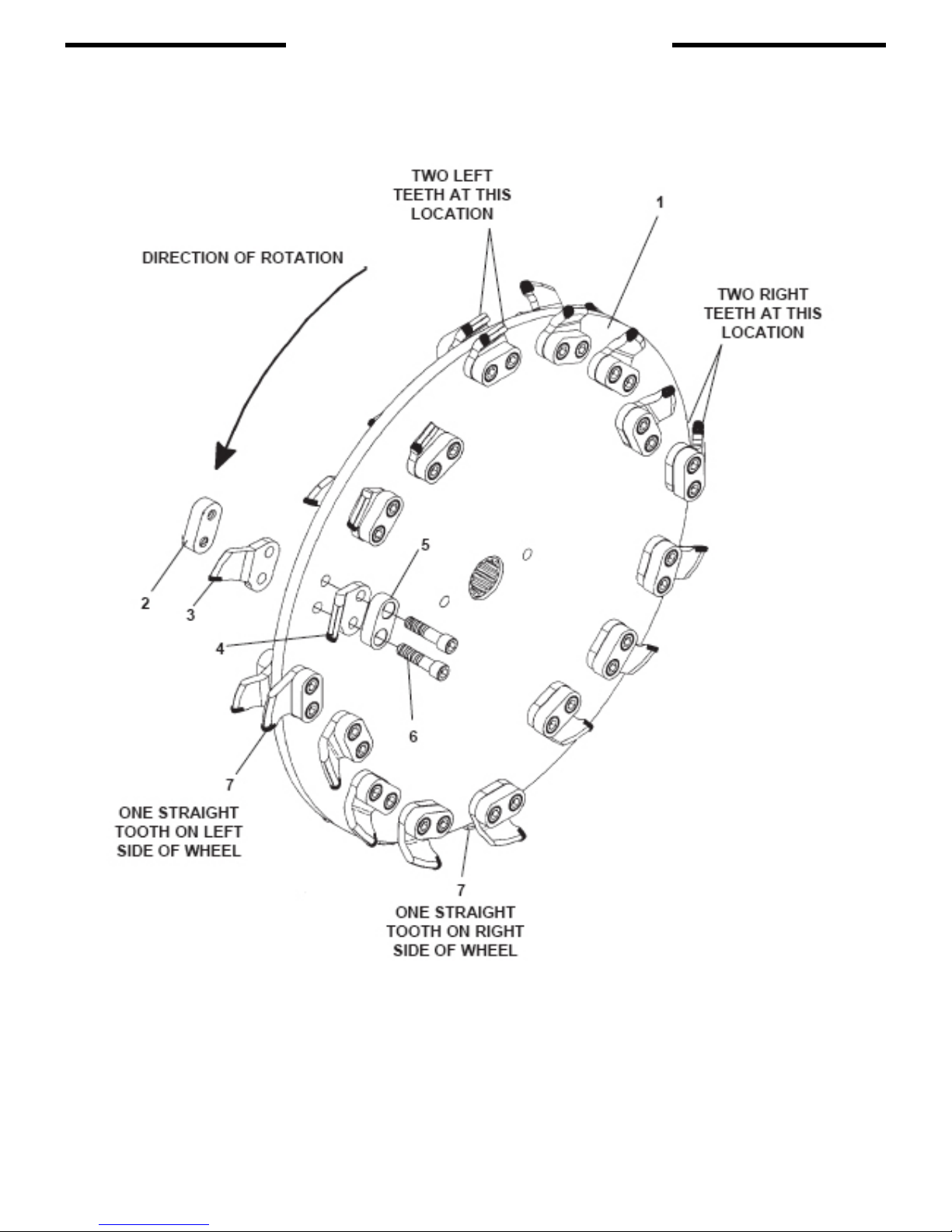
BOLT-ON TOOTH WHEEL ASSEMBLY
9768
8-9-04
E E
26” STANDARD FLOW WHEEL ASSEMBLY #101234
30” HIGH FLOW WHEEL ASSEMBLY #100418
This manual suits for next models
1
Table of contents


