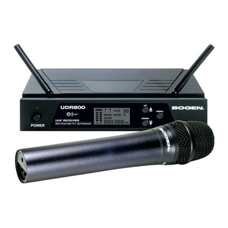
digi-tech AM-4119 User manual

Single UHF Microphone System
User Manual
AM-4119
AM4119_Manual_V2.indd 1 7/09/2016 11:22 AM

Please read this user manual carefully before using the product and retain the user manual for
future reference.
WARNINGS
• Consult the details of this manual for safe and operation of the AM-4119 unit.
• Keep this instruction in a safe place for reference when needed.
• Only use the attachments provided or those approved by the manufacturer.
• Only the power voltage labelled on the power adaptor can be applied to the operation of this
instrument. Make sure whether the local city voltage is suitable.
• It can be dangerous to open and dismantle the case of the AM-4119 in order to conduct any
repairs by yourself. The repair process should be done by a qualied technician.
• Please abide by the warnings and cautions outlined in this manual.
• The AM-4119 should be kept away from high humidity, heat, electromagnetic elds and direct
sunshine. Please disconnect all the connects cables and power supply and remove the
batteries when not in use.
TROUBLESHOOTING
1. The receiver is turned on, but the indicator light is not showing.
Make sure if the power cable is connected on powered on and the socket is in good condition.
2. When you speak into the microphone, the AF light ashes, but no sound is heard from
the connected speaker?
Make sure the volume level is not set on a low level, and check that the audio cable is connected
correctly.
3. The effective signal distance between the microphone and the base station is close, but
the signal is not being received.
• Check that the antennas have not become dislodged or damaged.
• Check is a battery change is required in the microphone.
• Check the location of the receiver and base station. If there is a strong magnetic eld in your
surroundings, the signal may be impeded.
4. The timbre is bad.
• Check that the voltage of the battery is sufcient and if a change is required.
• Check if there are the other products in the vicinity operating on the same UHF frequency as
the AM-4119. Do not use two devices with the same frequency at the same time in a place.
(Separate them at least 100m.)
2
AM4119_Manual_V2.indd 2 7/09/2016 11:22 AM

System Installation And Manipulation(receiver)
For a perfect receive consequence, the receiver should be installed at
the place of at least 1m above the ground, The audio head should not
face on the loudspeaker close at hand. It is necessary to use the system in
different carrier frequency and products from the same manufacturer.
When there are several instruments equipped in one case, utilize of
external high-gain antenna+signal distributor to enlarge the range of
utilization and save space would be a first priority.
Put the receiver in a stable place . connect the antenna, balanced cable
AF line , adapter power line provided by the manufacturer. Connect the
other end of the balanced cable to the balanced input joint of audio
adjustment table. Pull out the antenna thoroughly vertical to the ground
level.
Apply the voltage adapter to the socket, switch on the receiver power,
while the receiver in stand-by, turn on the power of rear and fore end
instrument of the audio amplification system.
: Open up the battery compartment insert the battery then close the
cover. Switch on the handheld transmitter while there is a temporal flash
of power light. Signal level of the receiver light up,a effective signal is
received. Adjust the channel volume and back loudspeaker instrument
to adequate volume output of the system. When AF level lightup
gradually corresponding to the volume, so the system function normally.
: There are two grade in the transmitter power switch that means thereis
no audio function when turn on transmitter power, the other is the grade
in normal use, there is a audio function while the power in on.
System Installation And Manipulation(transmitter)
45
:Pickup cover
:The light of low voltage
:The power switch of transmitter
:The battery room of transmitter
Transmitter.(handheld)
1
2
3
4
① ②③ ④
O N
Transmitter.(body-pack)
:.AF input
:.Ant
:Battery room.
:.Low voltage indicator
5
6
7
8
9
:Power switch.
5
ON OFF
INPUT
67
9
8
TRANSMITTER (HANDHELD)
1. Pickup Cover
2. The Light of Low Voltage
3. The Power Switch of Transmitter
4. The Battery Room of Transmitter
CONTROL PANEL & FUNCTION RECEIVER
Receiver.
6
1.Turn on the receiver, but the indicator is not lighted?
Make sure if the power cable is well fixed .is the socket in
good condition.
2.When you speak ,the AF light twinkies, but no sound
output?
Make sure if the volume keep in lowest place, or the audio
cable is not fixed well.
3.The effective signal distance becomes close. And signal
receiving is not will?
Perhaps you have not put out the antennas.
Perhaps you should change a new battery.
Perhaps the receiver is not put in right place.
Perhaps there is a strong magnetic field in your surround-
ings.
4.Timbre becomes bad?
Perhaps the voltage of the battery is not enough .
You need change.
Perhaps there are the same frequency signals in your
surroundings.
Do not use two machines with the same frequency at the
same time in a place.
(Separate them at least 100m.)
☆
☆
☆
☆
Troubleshooting
3
Control Panel And Function
①:The light of ON/OFF switch.
②:Volume.
③:RF light.
⑤:Receiver antenna.
⑥:Power jack.
④:Power ON/OFF switch.
⑦:Balanced output connector.
⑧:Mixed output connector.
1
6 7
234
5
8
⑨:SQL.
⑨
1. The light of ON/OFF Switch
2. Volume
3. RF Light
4. Power ON/OFF Switch
5. Receiver Antenna
6. Power Jack
7. Balanced Output Connector
8. Mixed Output Connector
9. SQL
3
AM4119_Manual_V2.indd 3 7/09/2016 11:22 AM

DISTRIBUTED BY:
TechBrands by Electus Distribution Pty. Ltd.
320 Victoria Rd, Rydalmere
NSW 2116 Australia
Ph: 1300 738 555
Int’l: +61 2 8832 3200
Fax: 1300 738 500
www.techbrands.com
Made in China 4
SYSTEM INSTALLATION & MANIPULATION (RECEIVER)
For a best use please ensure that the base station (receiver) is positioned at least 1m above the
ground and is not facing the connected speakers.
It is necessary to ensure that the AM-4119 system is being connected in an area where no other
products are operating on the same frequency as the unit.
Place the base station (receiver) in a stable place.
Connect the correct audio cable and power supply to the base station (receiver).
Connect the other end of the audio cable to the input connection of your chosen equipment.
Adjust the antennas on the Base Station (receiver) to a vertical position ground level.
Connect the supplied power adapter to the wall socket and switch on the power.
SYSTEM INSTALLATION & MANIPULATION (TRANSMITTER)
Open up the battery compartment and insert the correct batteries (two AA batteries) then close the
cover. Switch on the handheld transmitter.
AM4119_Manual_V2.indd 4 7/09/2016 11:22 AM
Table of contents
Popular Microphone System manuals by other brands

Shure
Shure BLX Wireless System quick start guide
Electro-Voice
Electro-Voice MS2500 owner's manual

Panasonic
Panasonic SHFX70 - DVD HOME THEATER WIRELESS SYSTEM operating instructions
LOTRONIC
LOTRONIC Party LIGHT & SOUND PARTY-200UHF instruction manual
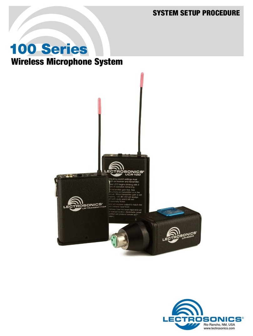
Lectronics
Lectronics 100 Series System setup procedure
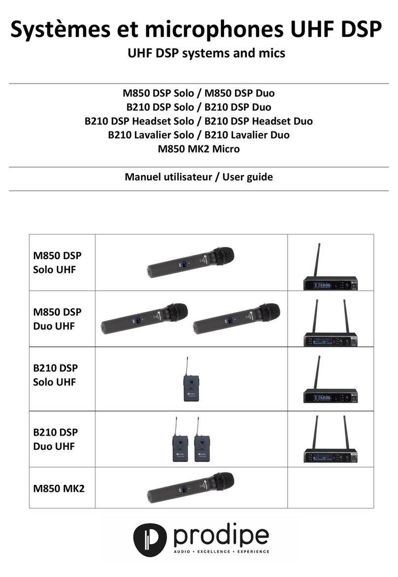
Prodipe
Prodipe M850 MK2 Micro user guide
