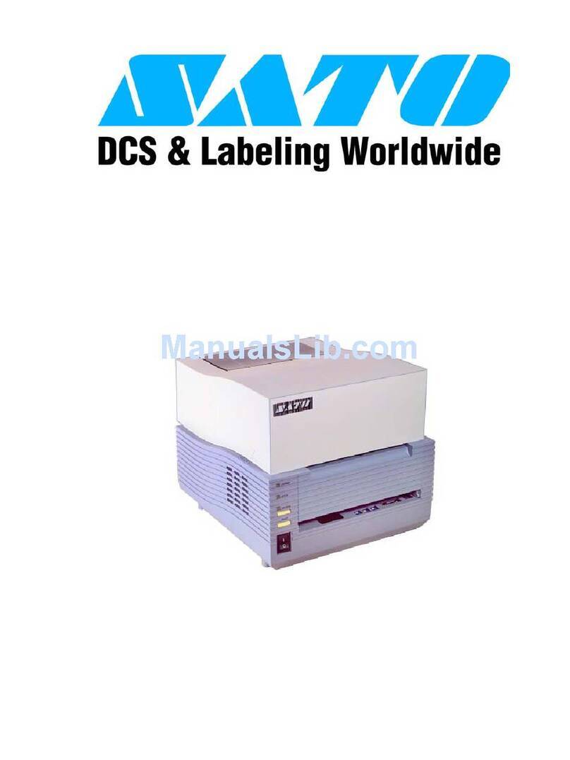
digi-tech 6612 User manual

MODEL 6610, 6612 & 6614
PANEL MOUNT PRINTER
OPERATOR'S MANUAL
DigiTec
State Route 2, Box 305
Newell, WV 26050
800-727-5646
FAX 304-387-1212
www.atcdigitec.com

TABLE OF CONTENTS
PRELIMINARY INFORMATION
Safety Summary
Important Messages
CMOS Caution
Shock Hazard
For Your Information . . .
1 GENERAL INFORMATION
1.1 Introduction
1.2 Unpacking Instructions
1.3 Instrument I.D.
1.4 Factory Assistance
1.5 Features
1.6 Specifications
2 INSTALLATION
2.1 Open Front Panel
2.2 Change Printout Variables
2.2.1 Select Font (Type Size)
2.2.2 Select Print Direction
2.2.3 Select Word Wrap
2.2.4 Select Calendar Format
2.2.5 Select Baud Rate
2.2.6 Select Data Bits
SUMMARY OF DIP SWITCH
CONFIGURATION
2.3 Interface Connections
2.3.1 Select RS232 or 20mA Interface
2.3.2 J4 Interface Connector
2.4 Turn Battery On/Off
2.5 Power Supply Connections
2.6 Load Paper
2.7 Change Ribbon
2.8 Test Printer
2.9 Printer Maintenance
2.10 Printer Assembly
3OPERATION
3.1 Standard Operation Mode
3.1.1 Front Panel Controls/Indicators
3.2 Set Clock Mode
3.2.1 Set Clock Mode (Entry Mode)
3.2.2 Set Lock Out Code
3.2.3 Disable Lock Out Code
3.2.4 Set Current Date
3.2.5 Set Current Time
3.2.6 Set Interval Time
3.2.7 Set Synchronization Time
3.2.8 Print Date and Time Only
3.2.9 Exit Set Clock Mode
3.3 Remote Terminal Operation
3.3.1 Data Transmission
3.3.2 Print Conditions
3.3.3 RS-232C Data Transmission Format
3.3.4 ASCII Character Set
3.3.5 ASCII Control Commands
3.3.6 ASCII Escape Commands
4 SCHEMATIC/ASSEMBLY DRAWINGS
5 PARTS LIST
ILLUSTRATIONS
Fig. 1 Open Front Panel, Locate S1/S2 DIP
Switches and Battery Enable (ON/OFF)
Jumper
Fig. 2Select Interface
Fig. 3 J4 Interface Connector
Fig. 4 Battery Enable
Fig. 5 Power Supply Connections
Fig. 6 Load Paper/Change Ribbon
Fig. 7 6610 Panel Cut-Out
Fig. 8 Front Panel, Std. 6610
Fig. 9 Front Panel, 6610 w/Clock
Fig. 10 RS-232C Transmission Format
Fig. 11A Typical RS-232-C Connection
Fig. 11B Typical 20mA Connection
Fig. 12 Main Logic Board Schematic
Fig. 13 Main Logic Board Assembly
Fig. 14 K Option Board Schematic
Fig. 15 K Option Board Assembly

PRELIMINARY INFORMATION
SAFETY SUMMARY
This instrument is designed to prevent accidental
shock to the operator when used properly.
However, no engineering design can assure the
safety of an instrument used negligently.
THEREFORE, READ THIS MANUAL CAREFUL-
LY AND COMPLETELY PRIOR TO OPERATION
OR ADJUSTMENT.Failure to do so could seri-
ously damage the instrument or injure the opera-
tor. Standard safety precautions must be used
during installation and operation.
Do not operate this instrument where flammable
gases or fumes are present. Parts must be
replaced by qualified repair persons.
IMPORTANT MESSAGES
<WARNING> Denotes a hazardous proce-
dure or condition which, if
ignored, could injure or be fatal
to the operator.
<CAUTION> Denotes a hazardous proce-
dure or condition which, if
Ignored, could damage or
destroy the instrument.
<IMPORTANT> Denotes a procedure or condi-
tion which is essential to the
correct operation of the instru-
ment.
<NOTE> Specifies supplementary, and
perhaps essential information
which should be recognized in
relation to a particular proce-
dure or condition.
CMOS CAUTION
This instrument contains CMOS (complementary
metal-oxide-semiconductor) circuitry which is sus-
ceptible to damage by static electricity. Turn off or
disconnect all power supplies before you make
any connections, DIP switch selections or signal
source applications.
When solder connections must be made (i.e.
replacing parts or zero-OHM jumpers), make sure
the soldering device is properly grounded.
Appropriate static ground conditions MUST be
observed (i.e. as with conductive sheet stock cov-
ers for workbenches, ground wrist-straps, etc.).
SHOCK HAZARD (INDUSTRY STANDARD)
“Shock Hazard,” is defined in Underwriters
Laboratories Radio and Television Receiving
Appliances Standards for Safety. 12th ed., 25
June 1969:
“Shock hazard shall be considered to exist at any
part involving a potential of between 42.4 Volts
peak and 40 Kilovolts peak in the following cases:
A. If the current through a load of not less than 500
OHMs exceeds 300 milliamperes after 0.003 sec-
ond.
B. If the current through a load of not less than 500
OHMs exceeds 5 milliamperes after 0.2 second.
C. If the time required for the current through a
load of not less than 500 OHMs to decrease to 5
milliamperes is between 0.1 and 0.2 second, and
the total quantity of electricity passed through the
load up to that time exceeds 4 millicoulombs.
D. If the time required for the current through a
load of not less than 500 OHMs to decrease to 5
milliamperes is between 0.03 and 0.1 second, and
the total quantity of electricity passed through the
load up to that time exceeds 75T-350T2milli-
coulombs (where T is the time in seconds).
E. If the potential is more than 5 Kilovolts peak and
if the total capacitance of the circuit is more than
300 micromicrofarads.
NOTE: Additional factors might apply when poten-
tials more than 40 Kilovolts are present.”
FOR YOUR INFORMATION ...
(1) DigiTec claims proprietary rights to the materi-
al disclosed herein. The following parts lists, com-
ponent layouts, and schematic drawings are
issued in confidence, for engineering information
only, and may not be reproduced by any means,
or used to manufacture anything shown, without
the direct written consent of DigiTec.
(2) Specifications, Parts Lists, Component
Layouts, and Schematics are subject to change
without notice.
(3) The terms “instrument,” “unit,” and “printer” are
used synonymously throughout this manual.

Section 1
GENERAL INFORMATION
1.1 INTRODUCTION
This manual is organized to provide the following
information:
Section 1: General Information
Section 2: Installation
Section 3: Operation
Section 4: Schematics, Assembly
Drawings
Section 5: Parts List
1.2 UNPACKING INSTRUCTIONS
While unpacking the instrument, carefully com-
pare the packing list from the shipping carton to
the purchase order to account for all Items
ordered.
Examine the shipping carton and its contents for
any damage. If damage is present or suspected,
notify the carrier immediately. Save the shipping
carton and packing material for future storage or
shipping.
1.3 INSTRUMENT I.D.
An instrument's serial number is a valuable refer-
ence for your records. The serial number for the
panel mount printer is on a plate located in the
lower left-hand corner of the instrument's rear
panel. Refer to this number when contacting the
factory about the instrument. You may want to
write the serial number here for future reference:
SERIAL NUMBER:
1.4 FACTORY ASSISTANCE
Because of the design complexity and use of
extensive test fixtures, the printer should not be
repaired by anyone but DigiTec service personnel.
If you encounter operating problems, please con-
tact DigiTec for instructions. Our address, tele-
phone number, and telex number are listed on the
title page of this manual. Be prepared to explain
the problem as thoroughly as possible. If the prob-
lem is a malfunction, indicate the operating mode
during which the malfunction occurred.
If the factory instructs or authorizes you to return
the instrument, ship the instrument PREPAID in
its original carton, with sufficient packing material,
to the nearest authorized service center (or as
directed).
IMPORTANT: The warranty of this instrument is
voided if customer modifies the instrument in any
way.
1.5 FEATURES
Model 6610 is a 24-column alphanumeric panel-
mount dot matrix impact printer that provides a
true EIA standard RS-232C/20mA I/0 port for
direct interface with a wide range of computer-
based equipment.
The important features and options of this Panel
Mount Printer include: selectable inputs; largest
available buffer; switch-selectable character fonts;
selectable word wrap; optional 2K nonvolatile
buffer; optional real-time clock with interval print;
popular power options; and custom configuration
for special OHM applications.
1.6 SPECIFICATIONS
PRINTER MECHANISM: Impact type. Dot matrix
typeface.
PRINT DIRECTION: Normal (first-line-down) or
inverted (first-lineup), selectable.
PRINTER SPEED: 42 lines per minute for NOR-
MAL print characters.
PRINTHEAD LIFE: 12 million characters.
PRINTOUT:
MODEL 6610: 24-column, addressable dot matrix
96 standard ASCII character set. Prints 24 NOR-
MAL characters per line, 12 WIDE or BOLD char-
acters per line.
MODEL 6612: 32-column, addressable dot matrix
96 standard ASCII character set. Prints 32 NOR-
MAL characters per line, 16 WIDE or BOLD char-
acters per line.
MODEL 6614: 40-column, addressable dot matrix
96 standard ASCII character set. Prints 40 NOR-
MAL characters per line, 20 WIDE or BOLD char-
acters per line.

WORD WRAP: Switch-selected ON or OFF
PRINT CHARACTERS: Four to choose (by switch
or remote command):
NORMAL (5 x 7) (1.7mm x 2.4mm);
TALL (5 x 14) (1.7mm x 4.8mm);
WIDE (10 x 7) (3.4mm x 2.4mm);
BOLD (10 x 14) (3.4mm x 4.8mm).
PAPER: Plain, inexpensive roll paper; 2.05" W x
80' L (57.2mm x 50.8mm); 7000 lines; fits 0.5"
(12.7mm) spindle; two rolls with purchase
REORDER: 24-roll case. Includes 12 ribbons,
either black 19-22459 or blue 19-22028.
RIBBON LIFE: >10,000 lines (2 characters/line);
50,000 lines typical
INPUT: RS-232-C (factory-setting) or 20mA cur-
rent loop
BAUD RATE: Selectable, 75-9600
START BITS: 1
DATA BITS: 7 or 8 (7 std.)
PARITY: Odd or even (not checked)
STOP BITS: 1 (others ignored)
RS-232-C INTERFACE: (+) and (-) 12V ±10%
OUTPUT POWER: 5V ±10% (1A max.)
DATA BUFFER: 48 characters standard (2 lines).
For Models 6610 and 6614: 128 characters stan-
dard (4 lines if Model 6612, 3 lines if Model 6614).
BATTERY BACKUP: Protects up to 30 days
(used with Option K)
NOTE: Battery may take up to 4 days to recharge
OPTIONAL MEMORY (OPTION M):2K byte
volatile buffer
NOTE: 2K buffer can be cleared by removing
power from the unit.
REAL TIME CLOCK (OPTION K):Battery-backed
internal clock prints time and date headers and
features a clock interval output pulse to trigger
external devices.
OUTPUT FORMAT:
DATE: mo/day/yr (std.) or day/mo/yr (Eur.)
TIME: hr:min:sec
ACCURACY: 2.7 secs./day (approx.)
POWER SUPPLIES AVAILABLE:
STANDARD: 5Vdc ±5%, ≤2.5A avg. while print-
ing. Standard power supply is connected at rear
panel terminal block.
IDLE CURRENT: 300mA
PEAK PULSE CURRENT: 3 Amps
IMPORTANT: Standard 5V amperage should be
maintained at 3A peak pulse current for 1ms to
avoid damage to printhead mechanism,
OPTION P: 85-132Vac at 47-440 Hz, 20VA avg.
while printing,
OPTION R: 9-35Vdc; ≤1.5A avg. while printing,
CAUTION: Although the power supply is short cir-
cuit protected, a sustained short of greater than
30 seconds may damage the supply.
ENVIRONMENT:
TEMPERATURE RANGE: 0-50°C (operating),
HUMIDITY: 5-90% RH (non-condensing).
STORAGE TEMP.: -25 to +85°C.
SHOCK, VIBRATION: ±5G, 3 axis, 0-50 Hz.
CASE:
PANEL CUTOUT: 2.78" x 4.50" (70.6mm x
114.3mm).
BEZEL: 5.70" x 2.87" (144.8mm x 72.9mm).
DEPTH: 8.75" (228.6mm);
WEIGHT:3 Ibs. 5-1/2 oz.
DIN ADAPTER KIT: Optional, fits std. DIN (72mm
x 144mm)

Section 2
INSTALLATION
INSTALLATION FUNCTIONS:
2.1 Open Front Panel
2.2 Change Printout Variables
2.3 Interface Connections
2.4 Turn Battery Backup On or Off
2.5 Connect Power Supply
2.6 Load Paper
2.7 Change Ribbon
2.8 Test Printer
2.9 Printer Maintenance
2.10 Printer Assembly
WARNING: Disconnect power before servicing
or adjusting the unit in any way.
2.1 OPEN FRONT PANEL
The printer's front panel must be opened for
access to the internal printer assembly. In order to:
Change Printout Variables (2.2)
Change Interface (2.3)
Turn Battery Backup On or Off (2.4)
Load Paper (2.6)
Change Ribbon (2.7)
HOW TO OPEN THE FRONT PANEL . . .
(refer to Fig. 1)
1. Open the front panel by pushing in the locking
fasteners on either side of the front panel. (Front
panel will flip down after fasteners are pushed in.)
2. Pull front panel away from unit until it stops.
3. At this time, you have access to the internal
printer assembly.
Figue 1. Open Front Panel, Locate S1/S2 DIP
Switches & Battery Enable Jumper
2.2 CHANGE PRINTOUT VARIABLES
The variables that determine printout format (how
data prints out) are factory-set but can be
changed during installation. The factory settings
(default settings) are:
VARIABLE FACTORY SETTING
Font *Normal
Print Direction *Normal (first line down)
Word Wrap ON
Calendar Format Standard (mo/day/yr)
Baud Rate 300
Data Bits 7
Interface Standard (RS-232-C)
Battery Backup ON
*These printout variables can also be changed
using Escape Commands from a remote terminal.
NOTE: However, that variables changed by
Escape Commands are not saved in memory
when the unit is turned off. Only changes made
during installation, while the unit is turned off, are
saved.
HOW TO SELECT PRINTOUT VARIABLES...
Printout variables are selected by adjusting the
positions of the 5 position S1 and S2 DIP switch-
es, which are located on the Main Logic Board
(found by opening the front panel).
NOTE:
1. Before adjusting the DIP switches, TURN OFF
ALL POWER. Switches are checked only on
power up.
2. DIP swithces are very tiny. Use a small, pointed
instrument to adjust swithces. Be careful not to
disturb adjacent settings.
2.2.1 SELECT FONT (TYPE SIZE)
SWITCH POSITION
SIZE SL-2 SL-S
NORMAL 0 0
TALL 1 0
WIDE 01
BOLD 11
0 = OPEN = OFF
1 = CLOSED = ON

2.2.2 SELECT PRINT DIRECTION
On many printers, data prints out upside-down
(first-line-down/NORMAL) while this presents no
problem once the printout tape is removed from
the printer, it can be difficult to read if the printout
is of immediate interest. With the 6610 printer you
can select the NORMAL print direction (first-line-
down) or an INVERTED print direction (first-line-
up).
SWITCH POSITION
DIRECTION SL-4
NORMAL 0
(first-line-down)
INVERTED 1
(first-line-up)
0 = OPEN = OFF
1 = CLOSED = ON
2.2.3 SELECT WORD WRAP
Word Wrap accommodates long lines of data with-
out hyphenation. When word wrap is selected, the
printer can print the same amount of information
as an 80-column printer, but without special for-
matting.
When Word Wrap is ON, the printer automatically
executes a CR LF (carriage return, line feed) at
the first space prior to printing the 25th character.
When Word Wrap is OFF, the printer executes a
CR LF as the 25th character after receiving 25
characters without a CR LF.
SWITCH POSITION
WORD WRAP SL-3
ON 1
OFF 0
0 = OPEN = OFF
1 = CLOSED = ON
2.2.4 SELECT CALENDAR FORMAT
When the Real Time Clock option (Option K) is
installed, one of two calendar formats can be
selected: mo/day/yr (STD) or day/mo/yr (EUR).
SWITCH POSITION
FORMATS1-1
STANDARD 0
(mo/day/yr)
EUROPEAN 1
(day/mo/yr)
0 = OPEN = OFF
1 = CLOSED = ON
2.2.5 SELECT BAUD RATE
INTERVAL
BAUD SWITCH POSITIONS PULSE WIDTH
RATE S2=2 S2-3 S2-4 S2-5 ON RTS
75 0 0 1 1 **120ms
110 1 1 1 1 90ms
150 1 1 1 0 60ms
*300 1 1 0 1 32.5ms
600 0 1 1 0 15ms
1200 1 0 1 1 7.5ms
2400 0 1 1 1 3.75ms
4800 1 0 0 1 2.75ms
9600 1 0 0 0 2.5ms
0 = OPEN = OFF
1 = CLOSED = ON
* Factory Setting
** NOTE: This time was measured when the print-
er was inactive. Interval pulse widths may be
shorter when printer is printing.

2.2.6 SELECT DATA BITS
SWITCH POSTION
DATA BITS S2-1
7 (standard) 0
81
0 = OPEN = OFF
1 = CLOSED = ON
2.3 INTERFACE CONNECTIONS
2.3.1 SELECT RS232 OR 20MA INTERFACE
The position of jumper W17 on the P17 header will
determine either RS-232-C or 20mA operation.
Refer to Fig. 2 for the correct RS232/20mA jumper
connection. The P17 header is located on the
Main PC Board, on the printer's rear panel.
Figure 2. Select Interface (W17 Jumper on P17
Header)
2.3.2 J4 INTERFACE CONNECTOR
J4 is a 25-pin, male, D-type interface connector,
located on the printer's rear panel (see below).
Figure 3. J4 Interface Connector
SUMMARY OF DIP SWITCH POSITIONS
S1 POSITION
VARIABLE 1 2 3 4 5
CHARACTER SIZE:
Normal 0 0
Tall 1 0
Wide 0 1
Bold 1 1
PRINT DIRECTION:
Normal 0
Inverted 1
WORD WRAP:
On 1
Off 0
CALENDAR:
MO/DAY/YR 0
DAY/MO/YR (EUR) 1
S2 POSITION
VARIABLE 1 2 3 4 5
BAUD RATE:
75 0 0 1 1
110 1 1 1 1
150 1 1 1 0
300 1 1 0 1
600 0 1 1 0
1200 1 0 1 1
2400 0 1 1 1
4800 1 0 0 1
9600 1 0 0 0
DATA BITS
7 (std.) 1
8 0

J4 CONNECTOR PIN-OUTS
PIN FUNCTION
1 Shield (chassis GND)
2 Transmitted Data (TxD) (not connect-
ed)
3 Receive Data (RxO) (input)
4 Request-to-Send (RTS) (output)
Usually LOGIC HIGH. A LOGIC LOW
state indicates BUFFER FULL and will
only accept 2 more characters. When
Clock Option K is installed, this pin
also functions as Interval Output, going
LOW long enough to transmit 10 bits
(indicating internal timer has timed
out).
7 Signal GND
11 +20mA current loop only
*18 +5V at 1A supply.
20 Data Terminal Ready (DTR) (output).
Usually LOGIC HIGH. A LOGIC LOW
state indicates either paper out, door
open, buffer full, TEST switch on, SET
CLOCK mode, or printer failure.
25 20mA current loop return.
* This 5V supply is not calculated as part of the
power specification.
2.4 TURN BATTERY BACKUP ON/OFF
(Refer to Fig. 4)
Option K (Clock Option) comes equipped with a
battery backup. The position of jumper W18 on the
P18 header, which is located at the front end of
the Main Logic Board, win turn; is battery ON or
OFF.
ON —> Position Jumper W18 on both pins of
P18 header.
OFF —> Position Jumper W18 on only one pin
of P18 header.
Figure 4. Battery Enable
2.5 CONNECT POWER SUPPLY
(Refer to Fig. 5)
All power supply connections are made using 18
gauge wire. Twisted pair or shielded cable input
lines are recommended on DC-powered units.
Standard and optional power supplies are as fol-
lows:
• STANDARD +5V DC POWER SUPPLY:
+5Vdc external power supply, ±5%, 2.5A average
while printing. (Fuse: 3 Amp fast-blow.)
• (OPTION P) 85 TO 132V AC POWER SUPPLY:
Optional 85 to 132V AC power supply, 47-440 Hz,
20VA average while printing.
IDLE CURRENT: 300mA.
PEAK PULSE CURRENT: 3 amps for 1ms (Fuse:
1 Amp slow-blow).
• (OPTION R) 9 TO 35V DC POWER SUPPLY:
Optional 9 to 35V DC power supply, ≤1.5A aver-
age while printing (Fuse: 2.5 Amp slow-blow).
• (Option S) 187 to 265V AC Power Supply:
Optional 187 to 265V AC power supply, 47-440Hz,
17VA average while printing.
CAUTION: Although the power supply is short cir-
cuit protected, a sustained short of greater than
30 seconds may damage the supply.
Figure 5. Power Supply Connections

2.6 LOAD PAPER
(Refer to Fig. 6)
HOW TO LOAD PAPER...
(1) Open the front panel for access to the paper
platen.
(2) Remove any remaining paper in the printer by
pulling it through the printer window, underneath
the tear bar.
CAUTION: Do not pull paper out from the back of
the printer. This could damage the print mecha-
nism.
(3) Remove spindle from used paper roll, and
insert it into the core of the new paper roll.
(Spindle is packed separately when shipped.)
(4) Place the paper roll in printer as shown in fig-
ure. Notice how paper feeds from roll (over the
top).
(5) Feed paper along paper path shown in figure.
Be sure the paper passes through the “Paper Out
Detector.”
(6) Insert paper into bottom of printer mechanism,
then press the FEED switch until a 1/2" of paper is
showing.
(7) Gently pull out about 3" of paper (from the front
of the printer), and feed the paper through the
printer window.
(8) Hold the paper securely, slide the printer
assembly back into place, then flip the front panel
back into place (until it clicks).
(9) Press FEED to advance paper to keep it from
binding.
2.7 CHANGE RIBBON
(Refer to Fig. 6)
HOW TO CHANGE THE RIBBON...
(1) Open front panel for access to the ribbon car-
tridge.
(2) Press the end of the ribbon cartridge marked
“PUSH/EJECT.” (The ribbon cartridge will swing
out from the right towards you.)
(3) Remove the ribbon cartridge.
(4) Before inserting the new cartridge, rotate the
cartridge dial in the direction of the arrow to tight-
en the ribbon.
(5) With the ribbon facing up, feed exposed paper
between the ribbon and the plastic cartridge body.
(6) Replace the cartridge on the printer mecha-
nism (it will click into place).
(7) Press FEED until 1/2" of paper is exposed,
then gently pull about 3" of paper from the front of
the printer.
(8) Feed paper through the paper window below
the tear bar.
(9) Hold the paper securely, slide the printer
assembly back into the unit, and flip the front
panel back into place (until it clicks).
(10) Press FEED to advance paper and keep it
from binding.
Figure 6. Load Paper, Change Ribbon

2.8 TEST PRINTER
(1) Turn printer ON.
(2) Press <TEST> key on front panel.
If everything is operating properly, the printer
will print the 96 printable ASCII characters
automatically.
NOTE: TEST characters always print out in
NORMAL (l.7mm x 2.4mm) size.
The Printer Test tells you whether:
• power connections have been made correctly
• paper is feeding properly
• the printer mechanism is operating normally
SAMPLE TEST PRINTOUT
hijklmnopqrstuvwxyz{l}~
PQRSTUVUXYZ[\]^_`abcdefg
89:;<=>?@ABCDEFGHIJKLMNO
!"#$%&< >*+,-./01234567
2.9 PRINTER MAINTENANCE
Proper maintenance of the printer mechanism
requires periodic cleaning.
NOTE: More extensive maintenance requires
factory assistance. Contact DigiTec when exten-
sive maintenance is required.
CLEANING: Use alcohol to remove grease or
stains. A hand-held vacuum cleaner is recom-
mended to remove loose dirt or debris.
CAUTION: Never use trichloroethylene- or
ketone-based solvents. These agents could dis-
solve or seriously deteriorate the plastic parts of
the printer mechanism.
2.10 PRINTER ASSEMBLY
Fig. 7 is an assembly/installation guide, illustrating
the printer's panel cut-out dimensions.
Figure 7. 6610 Cut-out Dimensions

Section 3
OPERATION
THREE MODES OF OPERATION:
Standard Operation Mode (3.1)
Set Clock Mode (for units with Option K) (3.2)
Remote Terminal Operation (3.3)
3.1 STANDARD OPERATION MODE
The standard Model 6610 printer is operated
using it’s front panel controls and indicators.
Figure 8. Standard 6610 Front Panel
3.1.1 FRONT PANEL CONTROLS/
INDICATORS
CONTROL/
INDICATOR FUNCTION
POWER When power is ON, this indicator
lights up (green LED).
PAPER When the printer is out of paper, this
indicator will light up red (red LED).
When the printhead mechanism
jams (malfunction), the red light indi-
cator will flash.
<TEST> Press this control key to print the
“test message” (which is the 96 print-
able ASCII characters). TEST char-
acters always print in NORMAL size.
<TEST> is ignored if pressed while
printer is printing.
<FEED> Press this control key to feed paper
out of printer. If <FEED> is pressed
while the printer is printing, printing
will be interrupted.
3.2 SET CLOCK MODE
When the Clock Option (K) is installed, the printer
has a 14-key front panel, used to set (program)
these clock variables:
Lock Out Code (entry password)
Internal Clock (current date, time)
Interval Time (time-to-print)
Synchronization Time (current time at
INTV)
IMPORTANT:
(1) To program any clock variables, the Battery-
Backup must be turned on (2.4).
(2) After the Battery-Backup has been turned on,
make sure the paper is properly loaded and the
front panel is in place (closed). If the printer runs
out of paper or the front panel is out of place, the
printer will automatically exit the “Set Clock Mode”
(entry mode).
Figure 9. 6610 Front Panel w/Clock Option
3.2.1 SET CLOCK MODE (ENTRY MODE)
TWO-MINUTE ENTRY TIME ...
A 2-minute entry time is allowed between setup
entries. If 2 minutes elapse without an entry, the
“Set Clock Mode” automatically ends, and the
printer returns to it’s Run Mode, retaining previous
setup entries.
TO CLEAR/CORRECT AN ENTRY ...
If an incorrect parameter entry has been made, it
cannot be cleared. Therefore, repeat the proce-
dure for that parameter entry.
TO ENTER THE SET CLOCK MODE . ..
Press: <M> and <C>.
NOTE: To exit the “Set Clock Mode” at any time,
you can (1) let the 2-minute entry time expire, or
(2) press <C> twice (<CC>).

3.2.2 SET LOCK OUT CODE
1. Press: <M> and <9>
2. Enter any 4 digits (as the Lock Out Code)
REMEMBER: Enter the Lock Out Code whenev-
er:
(1) the Set dock mode has been entered
(2) a change has to be made to the internal
clock
(3) the Lock Out Code itself is to be changed
3.2.3 DISABLE LOCK OUT CODE
The Lock Out Code is disabled by turning the
Battery OFF.
TO TURN THE BATTERY OFF ...
1. IMPORTANT: First turn OFF all power to print-
er.
2. Open the front panel and slide the printer
assembly forward.
3. Remove jumper W18 from its ON position (see
2.4).
4. Place jumper W18 in its OFF position (see 2.4).
This will erase all programmed internal clock data,
including the Lock Out Code.
5. Replace jumper W18 in it’s ON position.
6. Replace front panel and re-apply power.
3.2.4 SET CURRENT DATE
1. Press: <M> and <1>
(Printout: ENTER DATE).
2. Enter 6-digit date as mo/day/yr (STD) or
day/mo/yr (EDR).
EXAMPLE: For January 1, 1992 enter:
<M 1 0 1 0 1 9 2>
(Printout: 01/01/92)
3.2.5 SET CURRENT TIME
1. Press: <M> and <2>
(Printout: ENTER TIME).
2. Enter 4-digit time (based on a 24-hour clock) for
hours and minutes.Seconds are automatically set
to 00.
EXAMPLE: For 11:30 p.m., enter:
<M 2 2 3 3 0>
(Printout: 23:30:00)
3.2.6 SET INTERVAL TIME
1. Press: <M> and <3>
(Printout: ENTER INTV).
2. Enter 6-digit interval time in hrs:mins:secs.
EXAMPLE: To print every 1/2 hour, enter:
<M 3 0 0 3 0 0 0>
(Printout: 00:30:00 INTV
__:__:__ SYNC)
The Interval Print feature of the Clock Option
enables printing at a pro-set Interval Time (INTV).
INTV tells the printer to send a time-to-print signal
to the host computer system.
NOTES:
(1) The Interval Time causes the printer to gener-
ate a signal only; it does not cause the printer to
print.
(2) If INTV is programmed with some number >59
(for seconds), >59 (for minutes), or >23 (for
hours), nothing will happen. The printer will not
print an error message or the numbers that were
entered.
(3) Interval output will not function properly at
9600 baud.
TO CLEAR INTERVAL TIME ...
1. Press: <M> and <3>.
2. Than press <000000> (6 zeros)
(Printout: INTV CLEAR).
IMPORTANT: If power is lost between interval
times, the first interval time on power up could be
twice as long as it should be. Additionally, if a 1-
second interval time is programmed and power
fails, it is possible that when power returns, the
real time clock and interval time will be set equal
to each other. This means the 1-second interval
time will not resume for 24 hours.
These conditions can be avoided by reprogram-
ming the interval or the synchronization times
after a power loss.
This applies only if the battery is ON.

3.2.7 SET SYNCHRONIZATION TIME (SYNC)
TO SYNCHRONIZE THE INTERVAL TIME WITH
THE INTERNAL CLOCK . . .
1. Press: <M> and <4>
(Printout: ENTER SYNC).
2. Enter 6-digit SYNC time in hrs:mins:secs.
EXAMPLE: Interval Time is set at 30 minutes and
a SYNC Time will be set at 3:30 a.m. (03:30:00).
Therefore, the printer will generate a time-to-print
signal every 30 minutes, starting at 3:30 a.m.
Enter: <M 4 0 3 3 0 0 0>
IMPORTANT: If synchronization is set at a time
earlier than the current time, the printer will not be
synchronized. The printer will not send a time-to-
print signal until the current time matches the
SYNC time (i.e. 24 hrs.).
3.2.8 PRINT DATE AND TIME ONLY
To print out the current date and time while you
are in the Set Clock Mode:
Press: <M> and <5>.
3.2.9 EXIT THE SET CLOCK MODE
Press: <C> <C>.
REMEMBER: You can also exit the Set Clock
Mode by letting the 2-minute entry period expire
without making an entry.
3.3 REMOTE TERMINAL OPERATION
The following information is provided to operate
the printer from a remote terminal:
Data Transmission (3.3.1)
Print Conditions (3.3.2)
RS-232-C Transmission Format (3.3.3)
ASCII Character Set (3.3.4)
ASCII Control Commands (3.3.5)
ASCII Escape Commands (3.3.6)
3.3.1 DATA TRANSMISSION
MODEL 6610: Standard data buffer is 48 charac-
ters. Printer speed is 42 lines per minute. Baud
rate is user-selected. When the data buffer con-
tains 46 characters, DTR (Pin 20 on RS232C port)
and RTS (Pin 4 of RS-232C port) will go LOW, and
only 2 more characters can be received.
MODEL 6612: Standard data buffer is 128 char-
acters. Printer speed is 30 lines per minute. Baud
rate is user-selected. When the data buffer cen-
talnes 126 characters, DTR (Pin 20 on RS-232-C
port) and RTS (Pin 4 on RS-232-C port) will go
low and only two more characters can be
received.
MODEL 6614: Standard data buffer is 128 char-
acters. Printer speed is 24 lines per minute. Baud
rate is user-selected. When the data buffer con-
taines 126 characters, DTR (Pin 20 on RS-232-C
port) and RTS (Pin 4 on RS-232-C port) will go
low and only two more characters can be
received.
3.3.2 PRINT CONDITIONS
MODEL 6610: Printout occurs when the 25th
character is received (TALL, BOLD, and WIDE
characters use 2 character spaces in a printed
line), or ...
MODEL 6612: Printout occurs when the 33rd
character is received (TALL, BOLD & WIDE char-
acters use 2 character spaces in a printed line), or
MODEL 6614: Printout occurs when the 41st
character is received (TALL, BOLD, and WIDE
characters use 2 character spaces in a printed
line), or ...
• when a Line Feed (LF) is received,
• when a Carriage Return (CR) is received,
• when a Vertical Tab command is received,
• when a Form Feed command is received.
3.3.3 RS-232-C DATA TRANSMISSION
FORMAT
1 Start bit
7 Data bits (std)
1 Parity bit (odd/even, not checked)
*1 Stop bit (others ignored)
START BSB 2 3 4 5 6 MSB PAR *STOP NEXT START
0 1 110 1 0 1 0 1
Logic 0 = SPACE = OPEN Logic 1 = MARK = CLOSED
*110 baud requires 2 stop bits.
Figure 10. RS-232C Data Transmission Format

3.3.4 ASCII CHARACTER SET
HEX HEX
CHARACTER CODE CHARACTER CODE
CHARACTER HEX CODE CHARACTER HEX CODE CHARACTER HEX CODE
@ 40 60 space 20
A 41 a 61 ! 21
B 42 b 62 ˚ 22
C 43 c 63 23
D 44 d 64 $ 24
E 45 e 65 % 25
F 46 f 66 & 26
G 47 g 67 ' 27
H 48 h 68 ( 28
I 49 i 69 ) 29
J 4A j 6A * 2A
K 4B k 6B + 2B
L 4C l 6C 2C
M 4D m 6D - 2D
N 4E n 6E . 2E
O 4F o 6F / 2F
P 50 p 70 0 30
Q 51 q 71 1 31
R 52 r 72 2 32
S53 s 73 3 33
T54 t74 434
U 55 u 75 5 35
V56 v 76 6 36
W 57 w 77 7 37
X58 x78 838
Y 59 y 79 9 39
Z5A z7A :3A
{ 5B { 7B ; 3B
\ 5C | 7C < 3C
] 5D } 7D = 3D
^ 5E - 7E > 3E
_ 5F ? 3F
3.3.5 ASCII CONTROL COMANDS
Fig. 11 depicts the topical connection between a
6610 printer and a remote terminal or sending
device. Following this illustration are the ASCII
Control Commands.
NOTE: The 2 examples of the “Print Clock” func-
tion, executed from a remote terminal using the
ASCII Control Commands.
NOTE: To execute a Control Command, press the
<CTRL> key simultaneously with the key listed in
the “Control” column.
Figure 11A. Typical RS-232C Connection
Figure 11B. Typical 20mA Connection
ASCII CONTROL COMMANDS
CONTROL FUNCTION HEX CODE
H Backspace 08
(Description: Clears previous character for a new
character. Command is ignored if a line is being
printed.)
I Horizontal Tab 09
(Description: Moves cursor to column 4, 9, or 15,
depending on location of cursor when command is
entered. If cursor is beyond column 15 when com-
mand is entered, a CR and LF will be entered.)
J Line Feed OA
(Description: Advances paper to the same column
on the next line without a CR. Command is
ignored if sent immediately after a CR.)
K Vertical Tab OB
(Description: Enters 5 carriage returns.)
L Form Feed OC
(Description: Enters 11 carriage returns.)
M Carriage
ReturnOD
(Description: Prints current line. Initializes buffer
for next line.)
[ Escape 1B
(Description: Escape (see Escape Commands).)
Delete 7F
(Description: Clears buffer or deletes current line.)
EXAMPLES: Execute the “Print Clock” function,
using Control Commands:
NOTE: The 2 examples provided here include
both time and date. Either may be printed inde-
pendently by omitting either the date or clock com-
mand.

NOTE To 6612 and 6614 Users: These models will
function as described below; however, because
they can print more characters per line, they have
additional capabilities. Soldering together solder
pad SP3 on the main logic board (see lower right
corner of the board layout shown in the figure on
the next page) will enable the 6612 and 6614 to
print Date, Time and Data on a single line, instead
of requiring two lines.
EXAMPLE 1: PRINT CLOCK AS HEADER
To print the clock and date as a header before a
block of data, simply transmit to the printer:
1BH, 54H, 20H, 1BH, 44H, 00H, 0AH
carriage return and line feed
print date command
space
print clock command
Printout: 09:40:00__05/13/85
[] <---(date will print out on next line)
EXAMPLE 2: PRINT CLOCK ON DATE LINE
To print the clock on the same line as the date,
transmit:
1BH, 54H, 20H, 1BH, 44H, 20H, 31H, 32H, 2EH, 33H, 00H, 0AH
carriage return and line feed
your date
space
print date command
space
print clock command
Printout: 09:40:00__05/13/85__12.3
3.3.6 ASCII ESCAPE COMMANDS
NOTE: To execute an Escape Command, press
the <ESC> key before pressing the key in the
“Control” column.
ASCII ESCAPE COMMANDS
HEX
CONTROL FUNCTION CODE
<ESC> H Print TALL 1B48
(Description: Prints all characters TALL
(1.7mm x 4.8mm).)
<ESC> N Print STANDARD 1B4E
(Description: Prints all characters STANDARD
(1.7mm x 2.4mm).)
<ESC> W Print WIDE 1B57
(Description: Prints all character WIDE
(3.4mm x 2.4mm).)
<ESC> B Print BOLD 1B42
(Description: Prints all characters BOLD
(3.4mm x 4.8mm).)
<ESC> D Print DATE 1B44
(Description: When Option K (clock option)
is installed, this command has the date
printed (as text or header).)
<ESC> T Print TIME 1B54
(Description: When Option K (clock option)
is installed, this command has the time
printed (as text or header).)
<ESC> E Print INVERTED 1B45
(Description: Prints all text FIRST-LINE-UP.)
<ESC> F Print NORMAL 1B46
(Description: Prints all text FIRST-LINE-


Figure 13. Main logic board assembly drawing.

Figure 14.
For units using P/N 146818A for U101, connect Pin 16 to VB and connect Pin 1 to ground.
K option board schematic.

Figure 15. K option board assembly.
This manual suits for next models
2
Table of contents
