digico SD9 User manual

SD9 Operation Manual
0-1
User Manual - Getting Started
To be read in conjunction with the SD Series Software Reference
UserManualVersionBforSoftwareVersions4.0.680+

SD9 Operation Manual
0-2

SD9 Operation Manual
0-3

SD9 Operation Manual
0-4
Copyright © 2014 Digico UK Ltd
All rights reserved.
No part of this publication may be reproduced, transmitted, transcribed, stored in a retrieval system, or translated into any
language in any form by any means without the written permission of Digico UK Ltd. Information in this manual is subject to
change without notice, and does not represent a commitment on the part of the vendor. Digico UK Ltd shall not be liable for any
loss or damage whatsoever arising from the use of information or any error contained in this manual.
All repair and service of the SD9 product should be undertaken by Digico UK Ltd or its authorised agents. Digico UK Ltd cannot
accept any liability whatsoever for any loss or damage caused by service, maintenance, or repair by unauthorised personnel.
Software License Notice
Your license agreement with Digico UK Ltd, which is included with the SD9 product, specifies the permitted and prohibited uses of
the product. Any unauthorised duplication or use of Digico UK Ltd software, in whole or in part, in print or in any other storage
and retrieval system is prohibited.
Licenses and Trademarks
The SD9 logo and SD9 name are trademarks, and Digico UK Ltd and the Digico UK Ltd logo are registered trademarks of Digico UK
Ltd. Microsoft is a registered trademark and Windows is a trademark of Microsoft Corp.
Digico (UK) Ltd
Unit 10
Silverglade Business Park
Leatherhead Road
Chessington
Surrey
KT9 2QL
England
Telephone: +44 (0)1372 845600
Fax: +44 (0)1372 845656
Email: [email protected]
WWW: http://www.digiconsoles.com
Manual Issue and Date: Issue B - 10th April 2014 - For Version 4.0.680+ Software
Licence Agreement
"Product": SD9 software product produced by Digico UK Ltd intended for use on Target Platform identified below.
"Target Platform": Digico SD9 Digital Console system.
In return for the payment of the one-time fee, the Customer (identified at the end of this Agreement) receives from Digico UK
Ltd a licence to use the Product subject to the following terms and conditions.
1. The Product may be used without time limit by the Customer on the Target Platform.
2. The Customer must register the Product with Digico UK Ltd. Registering the Product is deemed an acceptance of the terms and
conditionsinthisagreement.
3. TheProductanditslicencearenottransferable, and the Customer is notpermittedtoonward-licensetoanythirdparty. TheCus-
tomerindemnifiesDigico UK Ltd againstanyandall claims and actionsarisingfromthird party use ofcopiesoftheProduct made by
theCustomer.
4. TheCustomeragreesnottoattempttodecompiletheobjectcodeoftheProductotherwisethanincircumstancesspecificallyprovided
forbylaw,andthen only after consultation withDigicoUKLtd.
5. TheCustomeragreesnottouse,orlicencetheProductforuse,with equipment other than the Target Platform.
6. TheCustomer agrees not to modifytheProductwithouttheprior written consent ofDigicoUKLtd.
7. ThisAgreementappliestoanyenhancementorupgradesthatmaybecomeavailablefortheProduct.
8. This Agreement does not transfer any right, title, or interestin the Productto Customer exceptas specificallyset forth herein.
9. DigicoUKLtdreservestherighttoterminatethisAgreementuponbreach,inwhicheventCustomershallthereafteronlybeauthorised
tousetheProducttotheextentthat itscontractualcommitmentstothird partiesrequireandthenonly wheresuchcommitmentsrelate
touseof theProductasauthorisedintheforegoing provisionsoftheAgreement.
LIMITED WARRANTY - Digico UK Ltd warrants for a period of 1 year from the date of purchase of the Product, the Product will reason-
ablyexecuteitsprogramminginstructionswhenproperlyinstalled ontheTargetPlatform. Intheevent thatthisProductfailsto executeits
programminginstructionsduringthewarrantyperiod,theCustomer's remedyshallbetoreturntheProducttoDigicoUKLtd forreplace-
mentorrepair at DigicoUKLtdoption. Digico UK Ltdmakesnoother express warranty,whetherwrittenor oral withrespectofthis
Product.
LIMITATIONOFLIABILITY-Exceptasotherwiseexpresslyprovidedbylaw,(a)theremediesprovidedabovearetheCustomer'ssole
andexclusiveremediesand(b)DigicoUKLtdshallnotbeliableforanydirect,indirect,special,incidental,orconsequentialdamages
(includinglostprofitwhetherbasedonwarranty,contract,tort,oranyotherlegaltheory.)
Thisagreementis madeundertheLawsofEngland.
LICENCE NO:..................... ..........................................................
REGISTRATION DATE:..... ..........................................................

SD9 Operation Manual
0-5
Contents
1.1 Introduction .............................................................................. .......1-1
1.2 Manual Overview ..................................................................... .......1-1
1.3 Before You Start ....................................................................... .......1-2
1.3.1 Worksurface Layout .............................................................1-2
1.3.2 Screen Assignment ..............................................................1-2
1.3.3 Channel Banks .....................................................................1-3
1.3.4 Using the Control Surface ...................................................1-3
1.3.5 The Assigned Channel .........................................................1-4
1.3.6 The Master Fader ..................................................................1-5
1.3.7 Other Controls ......................................................................1-5
1.3.8 Channel Types ......................................................................1-5
1.4 Hardware Configuration.......................................................... .......1-6
1.4.1 Connections..........................................................................1-6
1.4.2 Audio I/O Panel......................................................................1-7
1.5 Configuring a Session .......................................................... .......1-10
1.5.1 Session Structure ...............................................................1-10
1.5.2 Assigning Faders to the Worksurface....................... .......1-11
1.6 Saving and Loading Sessions ............................................. .......1-12
1.7 Audio Sync .............................................................................. .......1-13
1.8 Routing Basics ..............................................................................1-14
1.8.1 Selecting Inputs & Outputs ................................................1-14
1.8.2 Ripple Channels .................................................................1-15
1.8.3 Channel Names ..................................................................1-15
1.9 Channel Processing.............................................................. .......1-16
1.9.1 EQ ........................................................................................1-16
1.9.2 Dynamics.............................................................................1-17
1.9.3Auxiliaries ............................................................................1-18
1.10 The Matrix............................................................................. .......1-19
1.11 Control Groups..................................................................... .......1-20
1.12 Solo Setup............................................................................. .......1-21
SD9 - Getting Started
1-1
1.1 Introduction
The Digico SD9 consists of a worksurface with an onboard audio engine and a range of onboard inputs and outputs. This can be
connected to multiple Input/Output Rack Units by CAT5 cable or MADI links which carry all the audio input and output signals.
The console worksurface consists of 2 sections that can control 48 mono or stereo input channels, 8 VCAs, up to 24 mono or
stereo busses, 12 Matrix inputs and 8 Matrix outputs, 16 onboard graphic EQs and 8 onboard stereo effects.
The left and right sections each have 12 assignable faders and 12 sets of assignable encoders and switches.
Either of these worksurface sections can be assigned to the centre touchscreen.
Multiple console setups can provide:
Front of House and Monitoring with a shared stage rack and gain tracking.
Remotecontrolofaconsolefromalaptopcomputer.
1.2 Manual Overview
This manual provides an overview of the desk, and describes some of the basic operating principles which the user will need to
understand in order to run the desk.
For full details on all SD software functionality please refer to the SD Series Software Reference Manual available for download
at www.digico.biz
The following typographical conventions are used in this manual:
Bold type is used to indicate that the text is an exact copy of the labelling either on a screen or on the worksurface.
An arrow bracket (>) is used to indicate a sequence of button pressing. For example, Layout > Fader Banks indicates that the
Fader Banks button is accessed by first pressing the Layout button.
SD9 - Getting Started
1-2
1.3 Before You Start
There are certain general operating principles and terms that should be understood before continuing to use this manual.
Please read this chapter carefully before proceeding.
1.3.1WorksurfaceLayout..............................................................
Mute and Channel Select Buttons
2
nd Function Button
O
ption/All Button
USB Port
Headphone Control
Talkback Control
Solo Buss Controls
Light Controls
A
ssignable Rotaries
& Screen Scroll
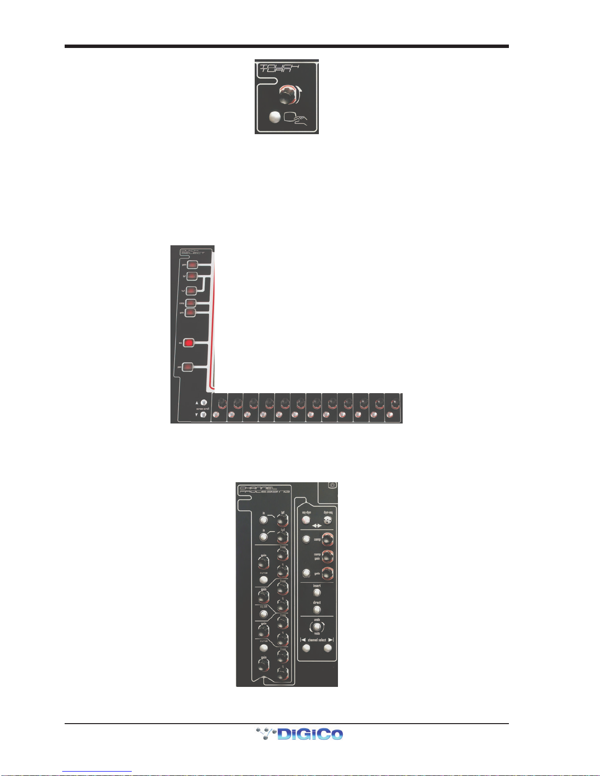
Channel Processing:
High and Low Pass Filters
4 Band Dynamic Parametric EQ
Dynamics Thresholds & On / Off
Channel Insert On/Off
Direct Out On/OffTouchscreen
Quick Select
Right ScreenAssign
Left Screen Assign
LCD Functions
Macro Buttons
Snapshot Control
Snapshot Previous/Ne
xt
Bank Select Buttons
B
ank Select Buttons
Master Level & Solo 1
Master ScreenAssign
Touch Turn Controls
1.3.2ScreenAssignment...............................................................
The SD9 has one central touchscreen which is used to access many of the console's functions.
There are 3 possible views that can be seen on this screen - Left section - Right section - Master screen
Each console worksurface section has its own Screen Assign button which, when pressed, will allow the channels in that
section to be viewed on the screen and controlled by the Channel Processing controls such as EQ and Dynamics. When the
button is lit, that section is assigned to the screen.
Therearealso aMaster buttonwhichallows you to viewtheMasterscreen.TheMaster screen gives accesstomanysetupandother
functionswhicharenotdirectlyrelatedtotheconsole'schannels.

SD9 - Getting Started
1-3
1.3.3 Channel Banks ......................................................................
The SD9's worksurface is divided into Banks. Each Bank contains twelve channels, and the channels which are currently active
on the control surface are defined using the fader bank buttons to the right and left of the faders:
A ‘bank’ is a set of twelve faders, and a "section" contains up to four ‘banks’. There are two sections of the desk, allowing up to
96 channels to be accessible on the worksurface.
To access a bank of faders, press the appropriate fader bank button. To switch both sections of the console to the same bank
level, press and hold one of the fader bank buttons.
The position of the banks on the worksurface is defined in the Layout > Fader Banks panel. By default, the Input channels will
be assigned to the first banks on the left and right sections of the console. The different output channels will be assigned to the
lower banks. Control Groups and Master fader will also be assigned. These bank assignments can be customised by the user and
saved in a session at any time.
1.3.4 Using the Control Surface ....................................................
There are two main ways in which all of the functions of the SD9 are accessed:
1. The touchscreen display, which can be controlled directly using a finger, or by using the keyboard and mouse
2. The physical encoders, switches and faders.
Note that when touching the screen directly, you may find it easier to use a finer point than your finger.
However, in order to prevent damage to the screen, it is important that you only use devices specifically
designed for touching screens (such as a pda stylus), and that you never press down hard on the screen.
A number of functions can be accessed in different ways, allowing users to operate the console using whichever interface they
prefer. This manual will describe accessing on-screen functions by touching the screen directly and not by using the mouse.
All of the physical controls found in the upper section are described in full within the relevant section of the manual and many
require no further introduction. The Master screen has a row of grey buttons which are used to access a range of configuration
displays. Pressing these buttons opens either a further drop-down sub-menu or a pop-up display. If a drop-down menu is
opened, pressing on one of its entries will open a pop-up display. The buttons lighten to indicate that their sub-menu or pop-up
display is open. A number of the buttons within each pop-up display generate further pop-ups.
The buttons within the pop-ups are coloured grey when their function is inactive, generally switching to a lighter shade of the
pop-up background when their function is active. Pressing on a text box opens a numeric or QWERTY keypad which can be
operated directly by pressing the screen or via the console’s external keyboard.
Pop-ups are closed by pressing the box in the top right-hand corner of the pop-up, marked CLOSE or CANCEL (or by pressing
CAN on keypad pop-ups).
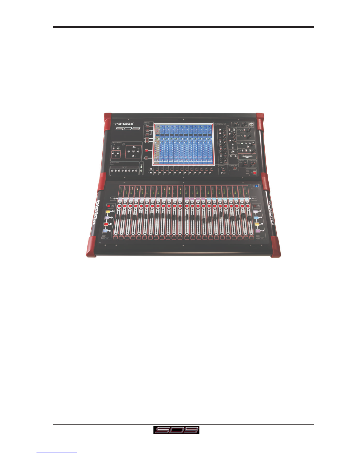
To the right and below the touchscreen is a single encoder and switch marked Touch-Turn (shown below). This is used to
access some of the rotary and switch controls within the Master screen. To assign the Touch-Turn encoder to a particular on-
screen control, touch the pot to be assigned. You will notice that a coloured ring appears around the on-screen pot, indicating that
it is assigned to the Touch-Turn encoder/switch.
SD9 - Getting Started
1-4
1.3.5 The Assigned Channel .........................................................
One of the channels in the Channel Strip panel is displayed in gold, indicating that it is currently the Assigned Channel. This means
that it has been assigned to the worksurface controls and can be configured in detail, as described below. To Assign a channel,
touch anywhere in the channel on the screen.
Once a channel is Assigned, all of the controls for that channel which are not displayed within the channel strip itself can be
accessed via secondary pop-ups, displayed by touching inside the relevant area of the channel. These pop-ups include controls
such as input and output routing and signal processing parameters.
A number of the physical rotary encoders on the control surface can be assigned to different on-screen pots. In order to ensure
that it is clear which function is assigned to which encoder, the assigned on-screen pot will have a coloured ring around it.
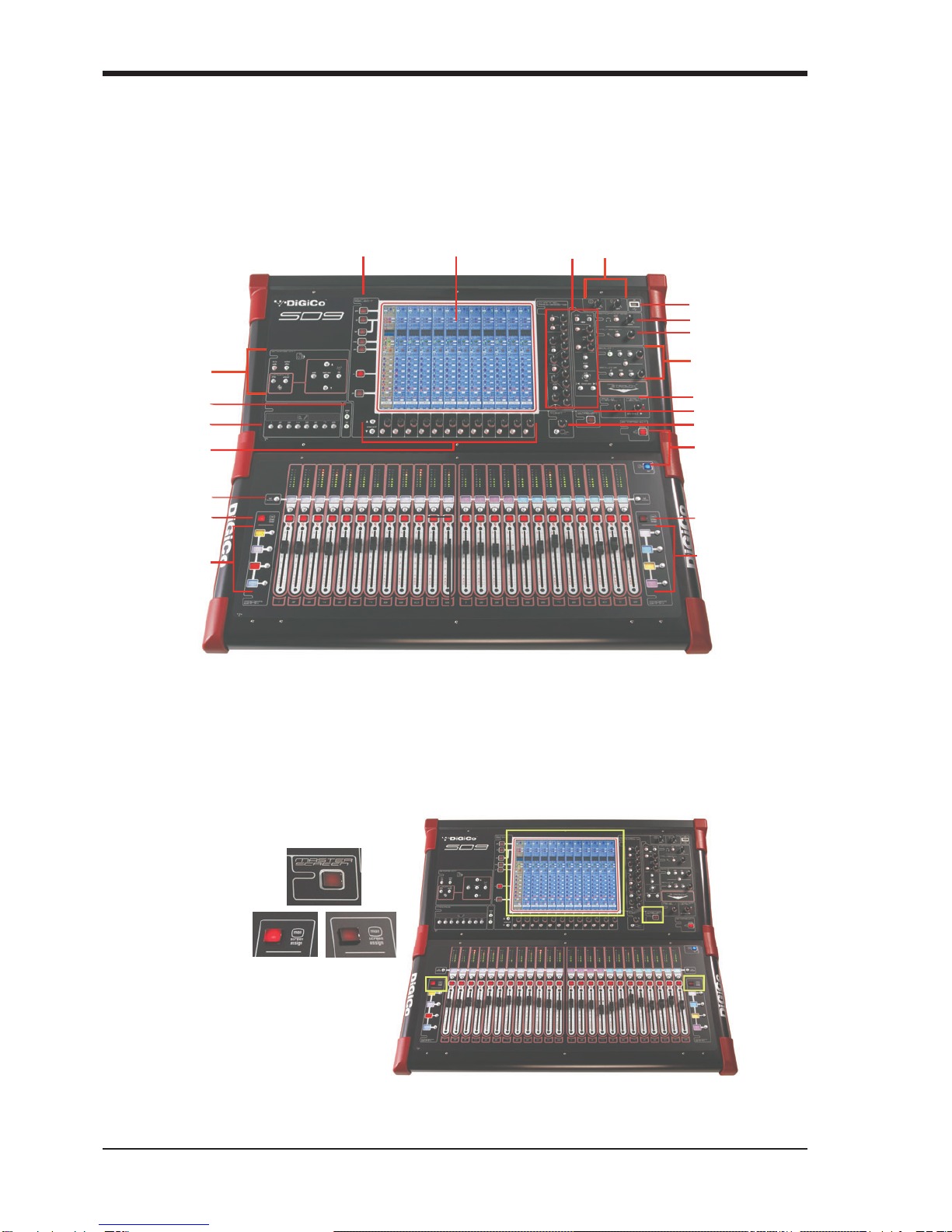
Thetwelveencodersandbuttonsimmediatelybelowthetouchscreen(shownabove)refertothechannelswithwhichtheyarealigned.
Pressingone of the Quick Select buttonson theleftof the screenwillassign the selected functiontothese controls belowthescreen. Six
auxsendscanbedisplayedintheChannelStrippanelat any one time. If more than six aux sends have beencreatedinthesession,the
scrollbutton outsidethebottomleft-hand cornerofthescreencanbeusedtoscrollthedisplaythroughtheremainingauxiliaries.
ThecontrolstotherightoftheChannelStrippanel allow the Assigned channel to be adjusted:
SD9 - Getting Started
1-5
1.3.6 The Master Fader..................................................................
By default, the master fader is assigned to the master group output, which is the lowest stereo group output by default. In
addition, the master fader can be assigned to the Solo buss 2 rotary control using the on screen button in the Solos panel on the
Master screen.
1.3.7OtherControls .......................................................................
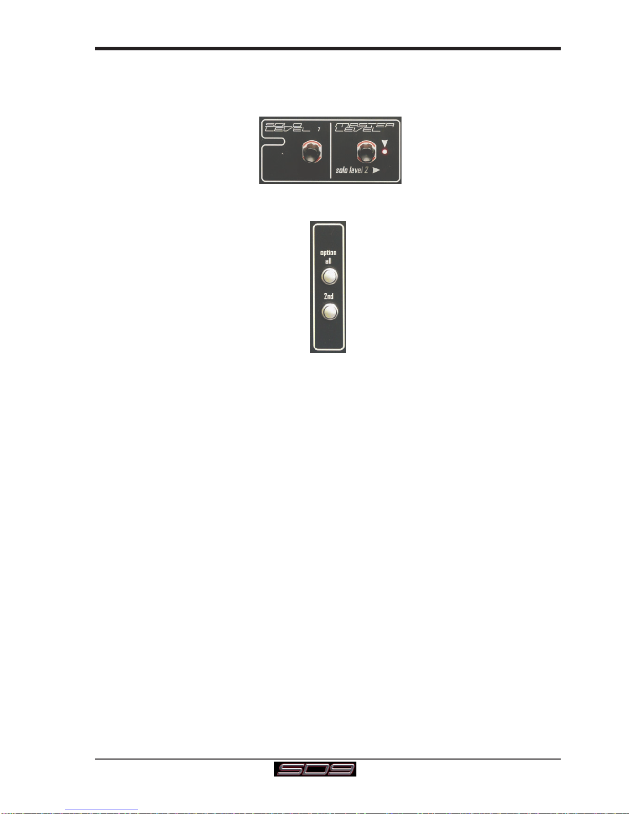
To the left of the screen are more channel controls: When pressed, the 2nd function button allows access to different param-
eters: 1) Stereo Aux Pan and Pre/Post switching
2) Hard Mute of a channel
3) Fine adjustment of Delay settings on output channels
The Option/All button has 2 main functions:
1) When pressed and released, any channel that is a member of a gang will be temporarily isolated from that gang.
2) When pressed and held, any parameter that is adjusted on a single channel will also be adjusted in the same way
on all of the channels in that bank
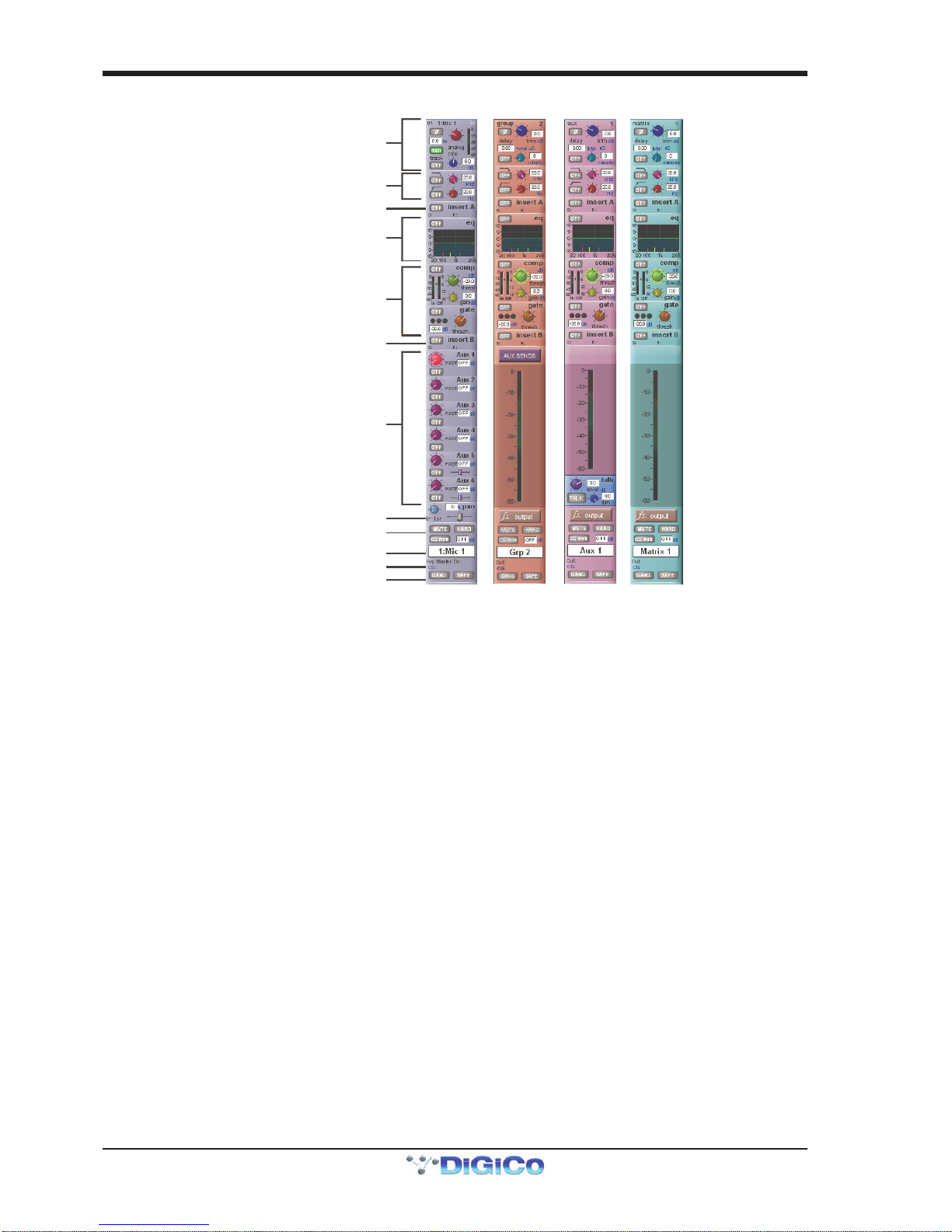
1.3.8 Channel Types ......................................................................
The signal flow of the SD9 is best understood in terms of the four channel types contained within it, shown below. Each channel
type offers full signal processing capabilities. As a summary, the four channel types are as follows:
- Input channels bring signals into the console to be mixed and sent to aux and group busses.
- Aux channels send a variety of mixes of the Input channels to the Aux outputs, mainly for use as monitor mixes and FX
sends.
- Group channels mix groups of input channels together, to feed the buss outputs or the output matrix.
- Matrix channels send the outputs of the matrix to the console’s main outputs (Optionally).
The Group channels, Aux channels and Matrix channels are all referred to as output channels. While the Aux and Matrix channels
are the channel types most commonly routed to outputs, all four channel types can be routed directly to outputs.
Channels are laid out in banks of 12 on the console worksurface and can be identified by their colour: Light-blue for Input chan-
nels, red for Group channels, purple for Aux channels and blue-green for Matrix channels.
By default, the Input Channels will be assigned to the top banks on the left and right sections of the console.
The output channels (Groups, Auxes and Matrices) will be assigned to the lower banks.
Control Groups will also be assigned to the lower banks. These bank assignments can be customised by the user and saved in a
session at any time.
Holding any bank or layer button down for a couple of seconds will switch both worksurface sections to the same bank level.
The controls on each different type of output channel are identical but an input channel has a number of additional features.
SD9 - Getting Started
1-6
Input Module - Touch to Expand
Analogue Gain/Digital Trim
Phase - Gain Tracking
Main/Alt Input Select
Inputs
Insert A Routing & On/Off
HPF/LPF
4 Band EQ
Touch To Expand
Dynamics
Touch To Expand
Insert B Routing & On/Off
Aux Sends
Touch to Assign Rows
Channel Pan
Mute & Hard Mute
Channel Label
R
outing Module - Touch to Expand
Gang & Safe Indicators
Groups
Auxes
Matrix
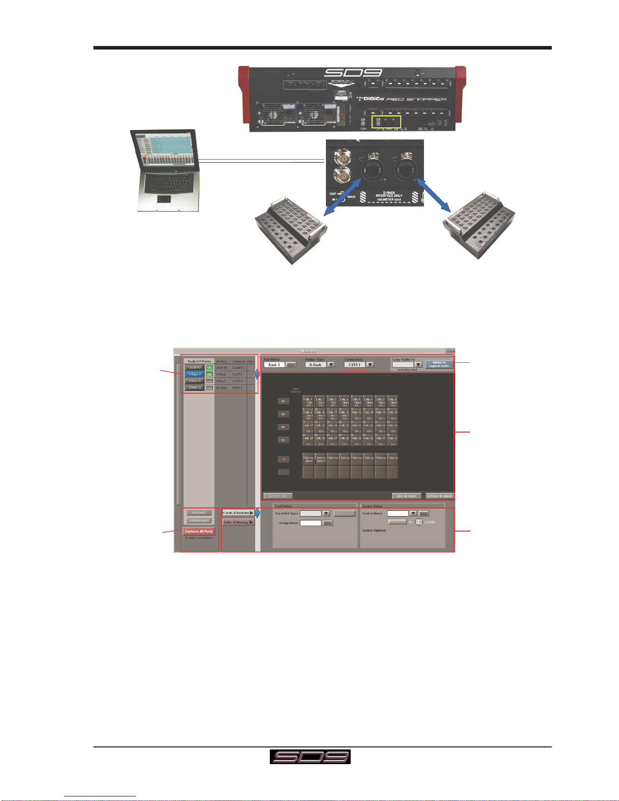
1.4 Hardware Configuration
1.4.1Connections ..........................................................................
Detailed information on the various systems of connection is provided in the relevant Appendix but the following diagram provides
an overview of a single console/ rack setup.
All connections should be made before switching on the console and racks.
The console and racks may each have dual redundant power supplies and both should be switched on at all times. After switch-
ing on the console the software will be launched automatically and the state of the worksurface and settings should be the same
as when it was last Shut Down.
To Shut Down the console press the System>Shut Down button and wait until you receive a message saying that it is safe to
switch the power off.
The SD9 worksurface has 8 analogue I/O and 2 AES I/O L/R pairs on its rear panel and additional I/O is supplied in the form of a
remote D-Rack which has 32 analogue inputs and 8 analogue outputs as standard. This rack is connected to the worksurface by
a 75M STP CAT5e cable. Optionally, 2 D-Racks can be connected to the SD9.
If used with a DiGiCo Little Red Box the CAT5e ports can also be used to connect with BNC MADI equipped consoles.
The console also has a pair of standard BNC MADI connectors (MADI IN & OUT) which can be connected to any of the range of DiGiCo
stageracks (DiGiRack, MaDiRack,MiNiRack or SDRack)with 75Ohmcoaxialcables. This MADIport could alsobeused toconnectto a
MADIequippedrecorder.
From Mid 2013, new SD9 consoles can also be fitted with optional Optocore connectors providing the possibility of including an
SD9 in a DiGiCo Optocore loop
The connection for the D-Rack is a single cable from the D-Rack port on the back of the console to the DiGiCo Audio Interface port
on the D-Rack.
In normal operation the MADI connections on Port 3 should be as follows:
Rack MAIN MADI IN connected to the console MADI OUT
Rack MAIN MADI OUT connected to the console MADI IN
SD9 - Getting Started
1-7
D-Rack 1D-Rack 2
PORT 3 MADI IN/OUT
DiGiRack
MaDiRack
MiNiRack
OR
MADI Recorder
DIGICO CAT5E
DIGICO CAT5E
1.4.2 Audio I/O Panel.....................................................................
The Audio I/O panel is used to configure the physical I/O connected to the SD9, including configuring and naming the sockets of
the cards installed in racks, and the setting of Pads and phantom power.
Local I/O : The SD9 provides local audio I/O in the rear of the console. These operate independently of connected racks..
To access the SD9 Audio I/O Setup touch Setup>Audio I/O on the Master Screen
The Audio I/O panel that opens is divided up into the following sections:
Port Selection
and Status
Global Port
Management
Configuration of
Cards & Sockets
or Splits & Sharin
g
,
as defined by
buttons to the left
Graphic
Representation of
Selected Rack
Selected Port’s
Properties
The left side of the window shows the ports. Each port relates to an available physical audio connection (Local IO, CAT5 or MADI
Port)
The section immediately to the right of this contains the controls relating to the ports. When a port is selected, this section changes
to reflect the status of the selected port, and allows it’s configuration to be changed as required.
The right hand section of the Audio I/O Window shows a graphical representation of the rack configuration connected to the
selected port. Depending on the port selected, the graphic will change, showing the available physical I/O. Each small “square” on
the image represents a single physical audio connection or socket, with these arranged in columns or rows, representing I/O
cards in racks, or the local I/O on the back of the console.
The section below the graphical rack picture allows configuration of the cards or slots and sockets, including custom naming,
phantom power and pad selection.
The local I/O configuration is fixed, so no hardware changes are possible. You can, however, change the Port Name, the Group
Names and the Socket Names (the name of each physical connector on a card).

SD9 - Getting Started
1-8
RackConnections
With a Rack selected in the left hand port selection list, the window will change to look something like the image below, depending
on the cards installed in the connected rack. The graphic shows the 6 available cards/slots, 4 input & 2 output.
In order to use the rack, the on-screen contents of the rack must match the cards physically installed in the rack connected. There
are two ways of achieving this :
Manual Conforming of Rack :
Select each card and manually select the appropriate card in the Card/Slot Type drop down menu in the lower section of the
window. Once the correct card type is selected, the Label at the bottom the selected card will turn green, indicating the card type
matches the card installed in the rack. If the Card Type name is Red, then there is a mismatch, and the error should be corrected
by selecting the correct card type.
Automatic Conforming of Rack :
Just below the rack view section of the window is the auto-conform all button. Pressing this button will correctly select the
correct card for each slot of the connected rack. Once complete, all of the Card Labels beneath each slot should turn green.
It is also possible to auto-conform on a card-by-card basis. With a single card selected (by touching any of the sockets on that
card), press the auto-conform button next to the Card/Slot type button selector in the lower section of the window. This will
automatically match the Card/Slot type for the connected rack.
Copying Audio and Listening to Copied Audio (MADI Recorder Setup)
Audio from one or two D-Racks can be copied to the MADI Port 3 Output by selecting the incoming Port(s) in the Ports list and
using the Copy Audio To drop down menu. For example, if you want to copy D-Rack 1 and/or D-Rack 2 Audio Inputs to a MADI
equipped recorder connected on Port 3, select Rack 1 in the ports list and then select Port 3 from the Copy Audio To drop down
menu. Then repeat the procedure for Port 2 copying this to Port 3 as well.
For 56 Ch Standard MADI,the 32 inputs on Rack 1 and the first 24 inputs on Rack 2 will be copied to Port 3 and can be recorded as
necessary.
For 64 Ch Standard MADI,the 32 inputs on Rack 1 and the 32 inputs on Rack 2 will be copied to Port 3 and can be recorded as
necessary.
In addition, by connecting the recorder's MADI Output to the console's MADI 3 Input, the playback can be monitored in the same
channels as the original source material. Just press the Listen To Copied Audio button to monitor playback and press it again to
return to monitoring the live sources from the rack.

SD9 - Getting Started
1-9
Edit the Port Name here.
Eg. Stage Rack, Local Rack etc...
Select Card Type manually or
using Auto-Conform function,
and edit Group Name
Selected Socket Properties
Edit Name and Socket options.
A
uto Conforming for all ports,
i
ndividual racks,
o
r individual cards
Select the contents of the bottom-right
corner of the Audio IO window
Select the port to be configured
Copy Rack Audio to MADI
StandardMADIConnections
If you have a standard MADI connection (not a DiGiCo Rack) to your SD9, you can set the SD9 to display the MADI with generic
signal names, i.e. MADI 1, MADI 2.. etc. through to MADI 56 or 64 instead of the usual rack style names. The naming does not
affect the signal, but makes routing signals easier.
STD MADI = 56 channel MADI
MADI 64 = 64 channel MADI
Console to Console routing
IftwoDiGiCoconsolesareconnectedtogether using MADI, it is possible torouteaudiobetweenthem.ThePortthatisconnectedtothe
secondconsoleshouldbedefinedasaStandardMADIConnection.
Unrouting All Outputs
Alloutputstotheselected port can beunroutedatoncebypressingtheunroute all outputs buttonbelowthe cards graphic and selecting
yesinthe warning pop-up whichappears."Copied"audioisnotunroutedbythisaction.
Note that this will cancel all routing created in the channel screens and cannot be undone.
Splits & Sharing
Inamulti-consolesystemwhereRacksare connectedwithMADIandshared betweentwoDiGiCoConsoles,onlyoneoftheconsolescan
takecontrol of therack,with respect toGain, Phantom PowerandPads. To overcomethis, it ispossibleto place theSD9 into oneof3
statesofoperation;Isolate,ReceiveOnlyorFullControl.
Sharing isconfigured in thebottom right-hand cornerof the windowwhen the Splits& Sharingbutton is selected:
Thesethreestatescanbesetindividually in the right column), on aper-rackbasis(middlecolumn),orgloballyforallsharedracks(left
column).
Isolate : The SD9 will not communicate with the rack and therefore any adjustment of input gain or +48V switch will have no
effect on the rack settings
Receive Only : The SD9 will receive the rack’s existing settings but will not be able to control the gain etc on the racks.
Full Control : TheSD9 willsend its settingsto theracks and change them accordingly.
SD9 - Getting Started
1-10
1.5 Configuring a Session
The SD9 has a default setup which means that the new user need not get involved in configuring the desk at this stage. However,
here is a brief overview of how the different displays are used in putting together a session. Each of the master displays intro-
duced below are described fully within the SD Series Software Reference Manual
The Setup >Audio IO display is used to configure the physical I/O connected to the SD9, including configuring and naming the
sockets of the option cards installed in racks, and the setting of pads and phantom power. (See previous section)
The File > Session Structure display is used for configuring how the console’s the DSP channels is to be divided between
channel types, and where the format of the channels is defined.
The Session Structure display can be used to automatically assign the channels to the worksurface. However, channels can
also be manually added to the worksurface using the Layout >Channel List display.
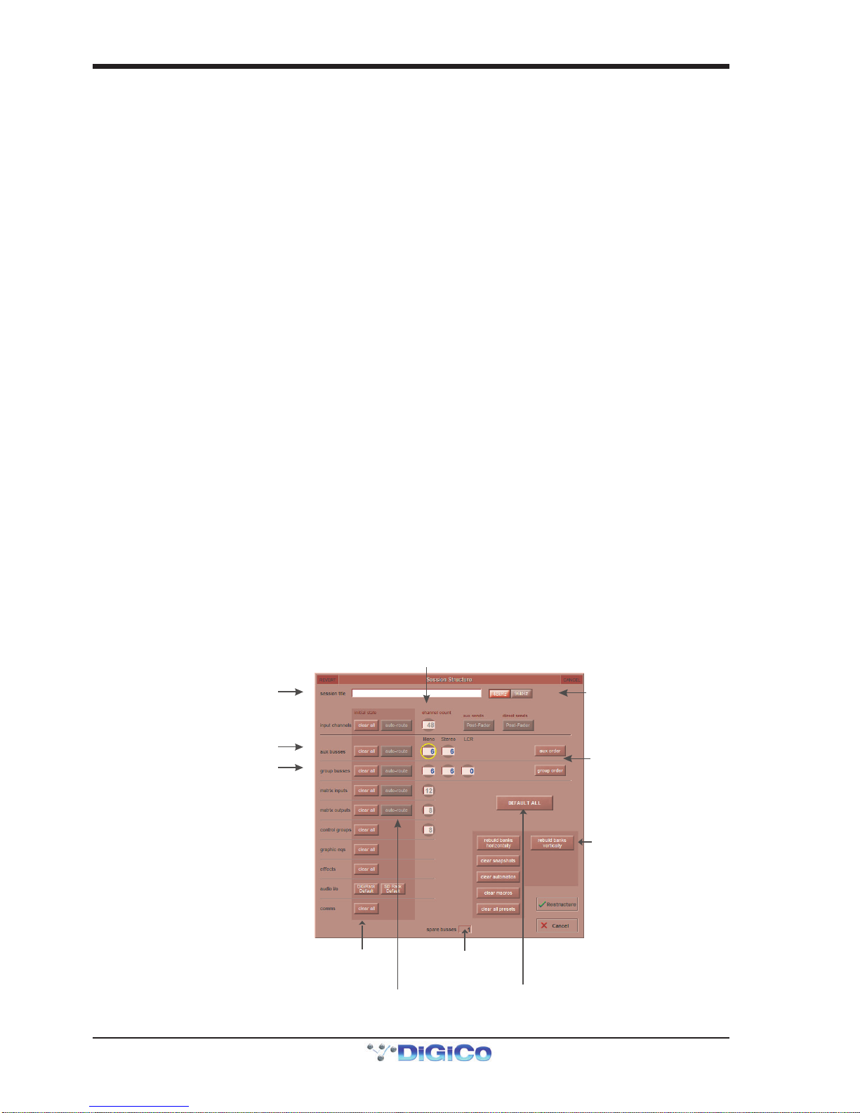
1.5.1SessionStructure..................................................................
When starting a new session, it is important to decide how many of each type of buss is required. While changes to session
structure can be made once a session has been started, it is best to try and set these parameters before configuring the session.
The structure will set the number and type of aux and group channels and allow you to choose which parts of the new session
will be cleared and reset. There is also an option to automatically route the inputs and outputs from channel types that you have
opted to clear.
To adjust any of the channel allocations, touch on the associated channel count box, and either enter a number using the pop-up
number keypad, or adjust using the assigned touchturn controller.
The maximum total amount of Aux and Group channels available is 16 mono or stereo. As you increase the number that you
require you will see the resources available decreasing accordingly in the number display at the bottom of the panel.
Note - Pressing the Default All button followed by the Restucture button will automatically configure a new
session with the following setup where the first 32 rack inputs are routed to input channels 1-32 and the
Master Buss is routed to Local outputs 1 & 2 and also to Rack 1 outputs 1 & 2. All input channels will be
routed to the Master Buss and the console headphones will be fed by the Master Buss when nothing else is
soloed.
The default configuration is :
48 Mono or Stereo input channels (Fixed)
6 Mono Aux busses & 6 Stereo Aux busses (Adjustable)
6 Mono Group busses & 6 Stereo Group busses (Adjustable)
12 Matrix Inputs and 8 Matrix Outputs (Fixed)
8ControlGroups(Fixed)
1 Stereo or LCR Master Buss
2Mono orStereoSoloBusses(Fixed)
Option to Clear
parts of the session
when restructuring
Option to automatically
route inputs/outputs
when using the Clear function
Create a default session
with flat parameters
and basic routing
Total number
of spare
busses
Touch number’s to
edit with pop-up
keypad or touchturn
Set number and type ofAux
S
et number and type of Group
Enter Session title
Select Session
Sample rate
Adjust Group
or Aux Order
Select Bank Layo
ut

SD9 - Getting Started
1-11
Clear All Buttons : When changing routing, you have the option of clearing any non-default routing or processing (EQ, dynamics
etc) from the channels in the session. This is especially useful when restructuring an existing session to make a new session.
The clear snapshots, clear automation and clear macro’s perform similar operations.
Rebuild Banks : When changing the session structure, there are two possible scenarios. If you restructure the session without
rebuilding banks, any additional channels you have allocated are not “placed” on the worksurface, and need to be manually
assigned to faders. If however, you restructure a session with Rebuild Banks enabled, the worksurface will be built with all
channels available on the worksurface.
Banks can be laid out horizontally or vertically according to the button selected
Aux Sends and Direct Sends : Bytoggling the state of theAux Sendsand Direct SendsButtons inthe Input Channels section, itis
possibletochangethedefaultoperationoftheAuxSendsandDirectSends.Thesefunctionstogglebetween“PostFader”,“Pre-Fader”
and “Pre-Mute”.These buttons canonly be usedin conjunction with the clearall function.
Auto-Route:TheAuto-routefunctionsautomaticallyroutesconsecutiveinputsforinputchannels,andconsecutiveoutputsforbusses.
Forexample,auto-routing 32 inputs willroutethefirst physical input (eg1:Mic1)to input channel1,thesecondphysical input (1:Mic 2)to
inputchannel 2… until youeitherrun out ofinputsor channels. Auto-routesareas follows :
InputChannelsauto-routewithphysicalinputs
Aux,GroupandMatrixChannelsautoroutetophysicaloutputs
MatrixInputsauto-routewithgroupoutputs
NOTE: Auto-Routing canonly beused inconjunction withthe “ClearAll” button.
1.5.2 Assigning Faders to the Worksurface ...............................
If,afteraSession Restructure wheretheRebuildBanksbuttonwasnotpressed,you find thatnewlycreatedchannelsdonotappearon
the worksurface,open the Layout>Channel List panel on theMasterscreenandyouwill see a fulllistofallinput and output channels
thatarepresentin the session.
Toassignchannels to the worksurface,selectabankand press the LCD Function button.
ThenpresstheChannelSelectbuttonbelowthedisplaylabelledCopy Bank From toenterthatmode.
Nowpress the firstchannel that youwish to assignon theLayout/Channel List on the Masterscreen.
Consecutivechannelswillbeassignedtotheworksurfaceforeachchannelintheselectedbank.
Now press the LCD Function button again and return to the standard mode by pressing the LCD button labelled Solo
Touch first channel
to assign
Press LCD Function button
thenAssign Faders
Press LCD button(s)
for Assignment
Open
Layout/Channel List
Click down arrow
to expand list
C
ustom Fader Assignments:
Press LCD Function button
then Copy Bnk From
Whole Bank Assignments:
SD9 - Getting Started
1-12
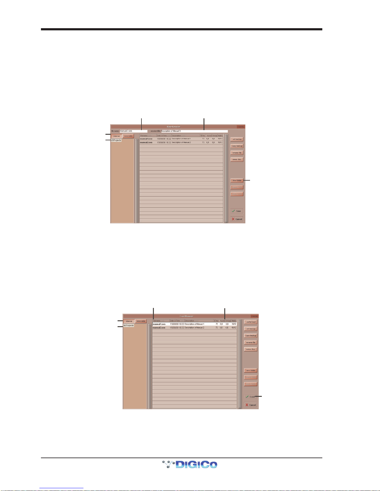
1.6 Saving and Loading Sessions
1.6.1 Save As New File .................................................................
When you change the configuration of the a session you should save it to the console's flash drive under a new filename.
If the Save Session panel has not appeared automatically after a session restructure then touch the Files button on the Master
screen and then press Save As New File.
Select the destination drive (Internal or Removable) and file path and then enter a new file name and description for the file - then
press the Save button.
Note: If you touch a session name on the existing list, this name will automatically be selected as the new file
name and touching Save will overwrite the old file.
Enter a Filename
Enter a Description
I
nternal files saved
in D:\Projects
Select Internal or
Removable USB
To create a new fold
er
in D:\Projects
1.6.2 Save Session ........................................................................
This button which is found above the Save As New File button will save the existing session in the same location and under the
same file name as it was previously saved or loaded from. It therefore serves as a "Quick Save" option to update an existing
session.
Remember that this function will overwrite your last saved version.
If you wish to save the session under a new name use the Files menu button and select Save As New File (See above).
LoadSession
To load a previously saved session:
Touch the Files button on the Master screen and then press Load Session.
Select the source drive (Internal or Removable) and the required file from the list - then press the Load button.
Select a File
File Details
I
nternal files saved
in D:\Projects
Select Internal or
Removable USB
Press Loa
d
SD9 - Getting Started
1-13
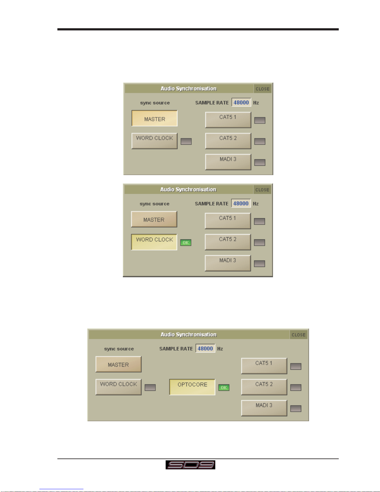
1.7 Audio Sync
The SD9 operates a Sample Rates of either 48000Hz (48kHz) or 96000Hz (96KHz).
Bydefault,itissettoclockinternally(asaMaster)andtheSamplerateis determined by your selection in the Session Structure panel.
Within a normal setup, the SD9 will usually remain as clock master. However, there are times when the SD9 needs to be clocked
externally. The Audio Sync panel allows you to control external synchronisation.
To access the Audio Sync Panel, touch the Setup Menu button, followed by Audio Sync. The following panel will open:
The SD9 will clock from the following sources : Word Clock, CAT5#1, CAT5#2 and MADI 3
Note : When a valid clock is detected on an external sync input, the corresponding Green OK box will light, even if that input is not
selectedas theclock source forthe SD9.
Thesecondpictureaboveshowsanexample of External Clocking: WordClock @ 48kHz
Note: If the console has an Optocore board fitted, an Optocore Sync option will also be available.
If the console is connected to an Optocore system then the Audio Sync should normally be set to Optocore if no external clock
sourceisrequired.

SD9 - Getting Started
1-14
1.8 Routing Basics
1.8.1SelectingInputs&Outputs...................................................
All channel input, output, insert send and insert return routing is done via routing displays, accessed via the dark grey routing
buttons in the channel Setup and Output displays (shown below for an Input channel’s input).
Note that multi-channel signals are routed individually, and then collected together as a "Multi Channel" as
described in the SD Software Reference manual
To access Channel Input Setup, touch the top of an input channel display on the touchscreen.
To access Channel Output Setup, touch the bottom of any channel type's display on the touchscreen.
Press Main Input
Label Channel
Mono/Stereo
Touch top of
Input Channel
Select or type
Number of Inputs
to Ripple Route
Select
Card
Select
Socket
Select
Rack
Select a Bank
Within each display, there are three columns containing three levels of routing selection:
- The left-hand column contains the available ports within which the desired input or output might be located;
- The middle column, signal groups, then shows the available groups of inputs or outputs within that port;
- The right-hand column, signals, then displays the individual inputs or outputs available within that signal group.
The boxes in each column are lit blue to indicate that they are currently selected. If there is already a routing assigned within the
display, the port and signal group columns containing the current assignment will be half-lit.
Each output can only have one channel routed to it. The outputs that are currently in use by another channel display in blue text. If
you attempt to route a different channel to an output which is already in use, a confirmation box appears, indicating which channel
is already using it, and warning that continuing with the action will cause the old channel to be derouted from this output. Press
Yes to proceed, No to cancel.
Note that when routing direct outs from Input channels or outputs from output channels, any number of
available signals can be selected. A new route selection will therefore be added to previous selections in
these cases. However, inputs, insert sends and insert returns can only route to/from one signal (in the case of
mono channels) or two signals (in the case of stereo channels). A new route selection will therefore result in
the previous selection being lost for inputs and insert sends and returns.
For stereo channels, left and right routes are presumed to be consecutive: When routing stereo signals, select the left route, and
the next signal in the list will be automatically selected as the right route. If the last signal in a signal group or port is selected as
the left route, the first signal in the following signal group or port will selected as the right route.
For input and insert return routing, the INTERNAL port provides the following signal groups:
Misc: The oscillator, white and pink noise generators.
Graphic EQs: The outputs of the SD9’s internal graphic EQ’s.
Effects: The outputs of any effects sends that have been created

SD9 - Getting Started
1-15
Channels: The direct outputs from the other input channels
Groups: The outputs of the group busses
Auxes: The outputs of the auxiliary busses.
Matrix: The outputs of the Matrix channels.
Note: The outputs for the channel being routed are locked out of the signal list.
Note also that the console views all routes as a single list. Therefore, if the left signal is connected to the last
signal in a port, the right signal, will be automatically connected to the first signal of the next port, regard-
less of port type.
For output and insert send routing, the INTERNAL port provides access to the inputs of the SD9’s Graphic EQ’s, and the inputs to
any effects that have been created.
The 0:Local I/O port contains a list of the inputs or outputs found directly on the SD9’s back panel.
The Rack ports contain all of the inputs or outputs available within the remote I/O racks, as defined in the Audio I/O display
Once a route has been selected, its name will appear below the routing button in the Setup or Outputs display.
Whenever a route is created, metering and additional controls are made available below the routing button. These controls are
dependent on the type of route created and are described in detail in the SD Series Software Reference manual:
Local Mic input routed to an input or insert return: 48V button for remote control of phantom power and a -20dB input pad
D-Rack Mic routed to a mono input or insert return: 48V button for remote control of phantom power and a -20dB input pad
D-Rack Mic or Local Mic Input routed to a stereo input:48V button, a -20dB input pad, MS decode, width, balance and L/R controls.
Mic pre-amp routed to an insert return: 48V button, a -20dB input pad, a phase reverse button and gain trim.
Output routed to a console output: -10db pad (rack out only), on button for switching the send on and off, gain
trim and send point selector which toggles the place within the channel from
which the direct output is fed:
pre-F Pre-fader,
post Post-fader
pre-M Pre-mute (and pre-fader)
Insert send routed to a console output: -10db pad (rack out only), on button for switching the send on and off, and
gain trim.
Insert send routed to a graphic EQ: an on button for switching the send on and off
Output routed to a graphic EQ: no additional control.
Buttons become ringed in either red or green to indicate that they are on.
1.8.2 Ripple Channels ...................................................................
The ripple channels function, located at the top of the route display, allows consecutive channel routes to follow the routing of
the current display incrementally. For example, Channels 1 to 8 direct outputs can be routed to Rack 1 > Line outs 1 to 8 respec-
tively by routing Channel 1’s direct out to Rack 1 > Line out 1 and allowing the ripple channels function to route Channels 2-8
automatically.
The number of channels to be rippled is defined either by selecting the appropriate grey numbered button, or by selecting the
keyboard button to the right of the numbered buttons, typing the required number of channels (8 in the example above) into the
numeric keypad which appears, and pressing OK. Once you have configured the ripple channels function, any routing action
will also effect the appropriate number of channels above the channel being routed.
The ripple channels function treats stereo channels as two channels. In other words, if Channel 2 in the above example is
stereo, the ripple channels function will route Channel 1 to Line out 1, Channel 2 Left and Right to Line outs 2 and 3, Channel 3
to Line out 4 etc.
1.8.3 Channel Names.....................................................................
The black and white text box in the Setup display is used for naming the channel. Channel names are displayed in the scribble
strip at the bottom of the screen. By default, the channel is given the same name as the selected input signal.
Note that if no input signal is selected, the scribble strip simply displays the channel number, prefixed by ch for Input channels,
and prefixed by Aux,Grp or Matrix in the case of output channels.
The following notes are specific to naming channels:
The Next button moves the entire Setup display to the next channel.
At the very top of the channel, the channel number and input signal name are displayed for Input channels, and the channel type
and number are displayed for output channels. These labels remain unchanged, regardless of any channel naming.
For Input channels, note that if the channel input signal is changed once a channel has been manually
named, the channel name will no longer follow the input signal name. To reactivate the automatic channel
naming function, clear the name and re-select the channel input.
Note also that the channel Output display also provides access to this channel naming facility.
Channels can also be named directly in the Channel List display (in the Layout menu). Open the display, activate the Edit
function below the list, and expand the required channel type list by touching its row. Touching the channel name column for
any channel in the list will cause a keyboard pop-up to appear, where a name can be typed in the usual way.
Table of contents
Other digico Music Mixer manuals


