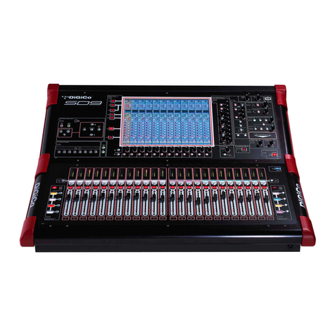
digico SD8 Installation instructions

SAFETY INSTRUCTIONS, SETUP &
INSTALLATION MANUAL
ISSUE A - OCTOBER 2009

Setup & Installation Manual
Page2
Theexclamationpointwithinanequilateraltriangleisintendedtoalerttheusertothepresenceofimportantoperatingand
maintenance(servicing)instructionsintheliteratureaccompanyingtheappliance.
WARNING:ApparatuswithCLASS1 construction shall beconnectedtoaMAINSsocketoutletwithprotectiveearthingconnection.
1 Readtheseinstructions.
2 Keeptheseinstructions.
3 Heedallwarnings.
4 Followallinstructions.
5 Donotusethisapparatusnearwater.
6 Cleanonlywith adrycloth.
7 Donotblockanyoftheventilationopenings.Installinaccordancewiththemanufacture’sinstructions.
8 Donotinstallnearanyheatsources,suchasradiators,heatregisters,stovesorotherapparatus(includingamplifiers)
thatproduceheat.
9 Donotdefeatthesafety purpose of thepolarizedorthegroundingtypeplug.Apolarizedplughastwobladeswithone
widerthantheother.
Agroundingtypeplughastwobladesandathird grounding prong. The widebladeorthethirdprongareprovidedfor
yoursafety.Iftheprovidedplugdoesnotfitintoyouroutlet,consultanelectricianforreplacementoftheobsoleteoutlet.
10 Protectthepowercordfrombeingwalkedonorpinchedparticularlyatplugs,conveniencereceptaclesandthepoint
wheretheyexitfromtheapparatus.
11 Onlyuseattachments/accessoriesspecifiedbythemanufacturer.
12 Useonlythe transportation cartonorcasesupplied bythemanufacturer.When this cartonorcase is used,usecaution
whenmovingthecartonorcase/apparatuscombinationtoavoidinjuryfromtipover.
13 Unplugthisapparatusduring lightning stormsorwhenunused for alongperiod of time.
14 Referallservicingtoqualifiedpersonnel.Servicingisrequiredwhentheapparatushasbeendamagedinanyway,such
aspowersupplycordorplugisdamaged,liquidhasbeenspilledorobjectshavefallenintotheapparatus,theapparatus
hasbeenexposedtorainormoisture,doesnotoperatenormally,orhasbeendropped.
14 Donotexposethis equipment to drippingorsplashingand ensure thatnoobjectsfilled with liquids,suchasvases, are
placedontheequipment.
16 TocompletelydisconnectthisequipmentfromtheACmains,disconnectboththepowerplugsfromtheACreceptacles.
17 Themainsplugsofthepowersupplycordandbothpowerswitchesshallremainreadilyoperable.

Page3
LesymbolereprésentantUnéclairfléchédaneuntriangleequilateralapourbutd’alerterl’utilisateurdeapresenced’une“tension
dangereuse>nonisoléeal’intérieurduboitierpouvantetred'uneforcesuffisantepourconstituerunrisqued’électrocution.
Lepointd'exclamationdaneuntriangleequiiateralapourbutd’alerterl’utilisateurdeIapresenced’instructionsimportantesconcernantIa
fonctionnernentetIamaintenance,dansIadocumentationquiaccompagnel’appareil.
ATTENTION: CetéquipementdeCLASSE1doitetreconnecteèauneprised’alimentationmunied'uneconnexionaIaterre.
1 Veuillezlirecesinstructions.
2 Conservezcesinstructions.
3 Respecteztouteslesconsignesdesecurite.
4 Suivezscrupuleusementtouteslesinstructions.
5 N’utilisezpascetappareilprésd'unpointd’eau.
6 Utilisezuniquementunchiffonsecpourlenettoyer
7 N'obstruezaucunedesouiesdeventilation.Installez-leenrespectantlesinstructionsdufabricant.
8 Nel'installezpasprèsdesourcesdechaleurtelsqueradiateurs,panneuxchauffants,etuves,ouautresappareils
produisantdeIachaleur(dontlesamplificateurs).
9 Nepas utiliserd’adapteur poursupprimer Ia prise de terre dec pricesa troisfiches. SiIa prise foumnie ne peut pas étre
branchéedansIapriseelectrique,adressez-vousaunelectricenquiremplaceraIapriseobsolete.
10 ProtegezIe cordon secteurafin que l‘onne marchepas dessus etqu’il ne soitpas pince,surtout au niveaudes prises, ou
al‘endroitouilsortdel’appareil.
11 UtilisezexclusivementdesfixationsetdesaccessoiresrecommandésparIefabricant.
12 Utilisezl’appareiluniquementavecIechariot,letrépied,lesupportouIatablespëcifiésparIefabricant,ouvendueavec
l’appareil.Siunchariotestutilisé,preneztoutesespreacutionsnécessairesIorquequevousdevezdeplacerl‘ensemble
(chariotetappareil)afinqu’ilsneserenversentpas.
13 Debranchezl’appareilenperioded’orageous’ildoitresterinutilisépendantlongtemps.
14 Confieztouteslesreparationsetinterventionsaunpersonnelqualifie.Uneinterventionestnecessairesil’appareilaete
endommagéd’unefaconoud’uneautre,sisoncordonousaprisesecteuronteteendommagés,siduIiquideaete
renverseousidesobjetssonttombésal’interieur;ouencoresi I’appareil a ete exposé aIapluieoual’humidite,s'ilne
fonctionnepasnormalement,ous'ilesttombe.
15 N’exposezpascetequipementauxéclaboussuresetveillezacequ’aucunrecipientremplideliquide,verreouvase,ne
soitposedessus.
16 Pourdeconnectercomplétementcetéquipementdusecteur,débranchezIaprisesecteurdelapriseelectrique.
17 Laprisesecteurdoittoujoursresterdirectementaccessible.

Setup & Installation Manual
Page4
Contents
SD8 Quick Start Guide .............................................................................. 6
Single Console with 1 MADIRack ............................................................ 6
FOH and Monitors Rig Using MADI......................................................... 7
Installation Introduction ........................................................................... 8
System Description .................................................................................. 8
The Worksurface....................................................................................... 8
Console Power Supply and Cooling ....................................................... 8
Worksurface Connections ....................................................................... 8
Headphone Connections ......................................................................... 8
Keyboard ................................................................................................... 8
Lighting ..................................................................................................... 8
User Option panels................................................................................... 9
Interface Rack Units and Modules .......................................................... 9
Rack Power Supply, Cooling ................................................................... 9
Rack Signal Earthing................................................................................ 9
Rack Control Panel Connections ............................................................ 9
Rack Modules ........................................................................................... 9
Rack Module Inputs and Outputs............................................................ 9
Example Installation ............................................................................... 10
Rack Module Connections..................................................................... 10
MADI Cabling Considerations ............................................................... 10
Synchronisation Connections ............................................................... 10
Timecode Connections .......................................................................... 10
Connections............................................................................................. 10
Worksurface Front Panel ....................................................................... 11
I/O Rack Control Panel ........................................................................... 11
I/O Rack Audio Connections.................................................................. 11
I/O Rack Units .......................................................................................... 12
Optocore® Optical Audio Data System (Optional) .............................. 12
Redundant Optical Operation (Optional).............................................. 12
Adjusting Settings in a Multiple Rack System ..................................... 12
Care of the optical cable system........................................................... 12
Checking the Optical cables.................................................................. 13
Setting Up External Display Monitors................................................... 13
Connecting an external screen ............................................................. 13
Note about LCD Monitors. ..................................................................... 13
Important Note for Installers.................................................................. 13
Paint Finishes & Colours ....................................................................... 13

Page5
Copyright © 2009 Digico (UK) Ltd
All rights reserved.
Nopartofthispublicationmaybereproduced,transmitted,transcribed,storedinaretrievalsystem,ortranslatedintoanylanguageinany
formbyanymeans without thewrittenpermissionof Digico UKLtd.Informationin this manualissubject to changewithoutnotice,and
doesnotrepresentacommitmentonthepartofthevendor.DigicoUKLtdshallnotbeliableforanylossordamagewhatsoeverarising
fromtheuseofinformationoranyerrorcontainedinthismanual.
Allrepairand serviceof the SD8product should beundertaken byDigico UK Ltdor its authorisedagents. DigicoUK Ltd cannotaccept
anyliabilitywhatsoeverforanylossordamagecausedbyservice,maintenance,orrepairbyunauthorisedpersonnel.
Digico (UK) Ltd
Unit10
SilvergladeBusinessPark
LeatherheadRoad
Chessington,Surrey
KT9 2QL
England
Telephone: +44(0)1372845600
Fax: +44(0)1372845656
Email: [email protected]
WWW: http://www.digiconsoles.com
Alltrademarksareacknowledgedasthepropertyoftheirrespectiveowners
Manual Issue: Issue A, October 2009
Electrical Safety Warning
Unlikemostlargeconventionalanalogueconsoles,theSD8worksurfacecontainsitsownmains
powersupply,andavarietyofinternalsupplyunitsandconverters.Thesearefullyinsulatedand
coveredtomeettherelevantelectricalsafetystandards,buttechniciansworkingwithintheconsole
shouldbeaware of thepresenceofmains voltage.
NotealsotherackPSUifoperatedremovedfromthechassishasheatsinksexposedthatare live to
mainsvoltage.
Also,SD8containsa number ofback-litflatscreen displays. The illuminationsystemof these
displaysuseslinevoltagesofuptoseveralKV,generatedbyhigh frequency DC - DC converters
locatedclose to thedisplays. Touchingor tampering with these circuitswill puta technician atrisk of
very damagingRF burns tothe skin and/or highvoltageelectricshock.

Setup & Installation Manual
Page6
SD8 Quick Start Guide
Ifyoutryingto getsoundsfromthemixerwithoutreadingthewholeinstallationandoperating manuals,pleaseatleastreadthispage first!
Single Console with 1 MADIRack ................................................
Detailedinformationonthevarioussystemsofconnectionisprovidedintheusermanualbutthefollowingdiagramprovidesan
overviewofasingleconsole/singleracksetup.
Optional Remote Control
Laptop connection with
E
thernet Crossover Cable
STANDARD CONNECTION WITH MADI
MAIN MADI
IN MAIN MADI
OUT
MADI 1AOUT
MADI 1A
MADI INPUTS
MADI OUTPUTS
MADI 1BMADI 2AMADI 2B
MADI 2A IN
MADI IN
MADI 1AIN
MADI 2AOUT
MADI OUT
MaDiRack
AUX MADI
IN AUX MADI
OUT
MADI 1B OUT MADI 1B IN
Optional
Redundant
MADI
Connection
SD8 Rear Panel MADI Connections
Optional
M
ADI Recorder
Or
S
econd MaDiRack
Allconnectionsshould bemadebeforeswitchingontheconsoleandracks.
Theconsoleandrackeachhavedualredundant power supplies andbothshouldbeswitchedonatall times. After switchingonthe
consolethesoftwarewillbelaunchedautomaticallyandthestateofthe worksurface and settings should bethesameaswhenitwaslast
ShutDown.
ToShutDown the consolepress the System>ShutDown button andwait until youreceive a messagesaying that itissafe toswitch the
poweroff.
TheSD8 worksurface has 8 analogue I/O and 8AES I/O onits rear panel and additional I/O is suppliedin the formof a remote MaDiRack
whichhas48 analogueinputs and 8analogue outputs asstandard. This rackis connected tothe worksurface by2 x 100Mhigh specifica-
tion 75 Ohm coaxial cables fitted with BNC connectors. This MaDiRack has two pairs of MADI connectors - Main MADI IN & OUT and
AUX MADI IN & OUT.
InnormaloperationtheMADIconnectionsshouldbeasfollows(seediagrambelow):
Rack MAIN MADI IN connected to the console MADI 1A OUT
Rack MAIN MADI OUT connected to the console MADI 1A IN
Note-Optionally, a secondsetofMADI cablescanbeconnected to provideMADIredundancy from therack’sAUX
MADI ports to the console’s MADI 1B ports
Theconsole’s MADI Port 2 can be connected toa MADI recorder(See Audio I/O Panel for setup details) ora second DiGiCoRack or
console.

Page7
FOH and Monitors Rig Using MADI.............................................
FOH & MONITORS
USING MADI ONLY
MONITORS
Audio Sync = MADI IN ON PORT 1
Uni-Directional Gain Tracking
FOH has control of the Analogue Gains
and Monitors can track this
OPTIONAL
LOCAL RAC
K
SHARED
STAGE RACK
OPTIONAL
LOCAL RACK
AUX
OUT
ONLY
PORT 1 IN
PORT 1
IN/OUT
PORT 2
PORT 2
MAIN
IN/OUT
MAIN
MAIN
FOH
A
udio Sync = MASTER

Setup & Installation Manual
Page8
Installation Introduction...............................................................
WelcometotheDigicoSDInstallationandconnectionmanual.Thismanualisprovidedforpurchasers,inordertohelp
theirinstallationandconnectionoftheirnewconsole.
Digicohopethatthis manual answersallthequestionswhichmaybeaskedbysystemdesignersandinstallers,but should there
beany issuesunresolvedforyourparticularinstallation,thelocaldistributororthefactorywillbepleasedtoassist.
IngeneraltheinstallationofaSDseriesmixerpresentsnoproblemswhicharesignificantly different from those of any other
largeformatlivesoundconsolewhenusedexclusivelyforanaloguesystemsandwhenusedindigitalsystems,integrationisnot
significantlydifferentfromotherdigitalconsoles.
System Description.......................................................................
The Digico SD console consists of a Worksurface, and 1 or 2 Input/Output Rack Units
Allthe console’s audioinputs and outputsare connectedto the Rackunits, andeach Rack unitsis connectedto the Worksurface
viaa pair ofdigital MADI links in eithercoaxial or within an Optocoreoptical format. Eachpair cancarry up to56 audioinputs and
outputs.
Thereare2pairsofMADIconnectorsavailableon theWorksurfacerearpanel,including2bidirectionalopticalMADIconnectors
(optional)allowingtheconnection ofupto2Rackunitsoralternativemadiconnections.Thisgives atotalcapacityof112
inputandoutputsockets.However,theconsoleisonlyabletoassignbetween60audiochannels(dependenton
version),sonot allthechannelsina2-madisystemcanbeused simultaneously.
EachRackmodulecontainsinputandoutputcards, which allow the sameRackunittoconnecttodifferenttypes of analogue and
digitalaudiodevices.
Aswell as connectingthe WorksurfaceMADI links toRack Units,you can alsoconnect themdirectly to any other MADIequipped
device,suchasadigitalmultitrackrecorder.
The Worksurface ...........................................................................
TheSDWorksurfaceis inmanywaysverysimilartoanylargeanaloguemixingconsole.One keydifference,however,isthatmost
analoguesignalsare connectedviatheRackunits.TheWorksurfacerearpanel doesincludeasmallnumberofsignalconnectors,
andsomeused onlyforsynchronisation,notforaudioI/O.
The Worksurface is supplied in 2 chassis sizes, for 24 input + 12 master section or 12 input + 12 master section faders.
Console Power Supply and Cooling...........................................
Unlikemostanalogue consoles,theSDWorksurfaceispowereddirectlyfromthemains,withnoexternalsupplyunit.Theinternal
mainssuppliesarehighlyefficient and requireonlylittleforcedcooling. A lownoiseoptionofthe Worksurface power supplyunitsis
available.
However,itis important thatairflowto the ventsonthe rear ofthe Worksurface arenotrestricted in anyway.
Notethere are 2 (Option) x IEC mainsinlets for the dual redundantsupplies. We recommend the use or aUPS to support the mixer in the
eventof“brown outs”and for generalpower conditioning. Ifthis isused,connect thisto 1 supplyonly, whilst theother supplyis directly
poweredfromthemains.In this way UPSproblemsarealsobypassed.
Worksurface Connections............................................................
Apartfromheadphonesandtalkback,alimitedamountof audioisconnectedtotheworksurface.Thisisprincipallyintendedtosignals
usedlocallytomixer,thebulkofconnectionsbeingintendedtobeconnectedviatheexternalrack.
Syncandcontrolconnectionsaredetailedlaterinthismanual.
Headphone Connections..............................................................
Thereisaheadphone connector witha1/4"(6.3mm) stereo jack underthearmrest. These will drivedownto 8 ohm loads,butnote
thereisconsiderablepower/voltageavailableatlowimpedance.Externalvolumelimitingshouldbeprovidedwhererequiredbylocal
regulations.
Keyboard........................................................................................
TheWorksurfaceunitincludes a smallcomputerkeyboard with integraltrackball.This is fittedtosockets on therearpanel and
storedin a spaceat thefront the consoleflight case(where this is factory supplied).Note thatthe mixer isintended tooperate with this
connected.Themixerwillfunctionwitthismissing,butcertainoperationscannotbeaccessedandtheboottimeisconsiderablyextended.
Lighting..........................................................................................
TheworksurfaceincludesoutputsforLitliteorcompatiblegoosenecktypenominal12Vdclamps.
Thebrightnessisadjustableby a panelscreencontrol.ThesearewiredtotheLilitefactorystandardwiringscheme.NotecertainLitlites
(especiallythosesourcedintheUK)maybetoanon-standardwiringschemeandneedtobecorrectedtofunction.

Page9
User Option panels .......................................................................
TheUppersectionoftherighthandworksurfaceincorporatesaremovablepanel. Afurther,smaller,removablepanelisfitted totherear
ofthemixerimmediatelybehindthesurfacepanel.
This isprovided sothat users canfit theirown custompanel, or adapt theexisting panel - thiscould beused formachine remotes, plasma
displays,Analoguemetersetc.
Undernocircumstancesshouldmainsvoltagesbeconnectedtothispanel.Suchsystemsshouldbecontrolledremotelybylowvoltage
circuits(maximum24V).
Notealsothattheinteriorofthemixerworksurfaceiselectricallyverynoisy,andcontainsavarietyofsensitiveelectroniccircuitsrunning
atveryhighclock-speeds.
DigicocannotberesponsibleforinterferencecausedbythemixertodevicesconnectedtotheAccessoryPanel,orforinterferencefrom
thepanelaffectingthe operationoftheconsole.Theconsoleshouldbecommissionedandtestedwithoutthisinstalledpriortotestinguser
externalsystems.
Interface Rack Units and Modules...............................................
Audiosignals are connected to the console viaRack Units.Each RackUnit isa 19-inch chassis with a control panelat thebottom.
Thereare3availablestyleofinterfacerack.MadiRack(standard for SD8) DigiRack and Mini rack.
TheMadirack is 8U (310mm) high with a fixed 48 mic/line input format with slots for up to 3 output only Rack modules
The Digirack is 9U (353mm) high with 14 card slots, each of which can accept a Rack Module, up to 7 input and 7 output modules
The Minirack is 5U (220mm) high with a total of 4 cards slots with may be input or output or a mix of both.
EachRackis astandard 19" wide, Theunits are 365mmdeep, excludingconnectors.
Rack Power Supply, Cooling .......................................................
RackUnitshavetwinsupplies each withtheirownseparate mains power connections,2IECmains inputs per rack.
Atleast1U(45mm)ofspaceshouldbe left above and below the rack unittoallowventilation,andtopreventheat
transferfromadjacentequipment.Atleast200mshouldallowedtosideoftheunitstoallowheatdisippation.
Atleast100mm/4"shouldbelefttheconnectorside of the rack toallowventilation.Howeverthisclearanceisusuallyrequiredtoallow
connectoraccess inanycase.,
Rack Signal Earthing ....................................................................
TheanalogueearthingrequirementsoftheRackunitissimilartothoseofaconventionallargeanalogueconsole.Allanalogue
inputsandoutputsarebalancedandsymmetrical,butnotfloating,becauseoftheirtransformerlessdesign.Installersshoulduse
goodearthingpractice,aswithanylargeaudioinstallation.DigicocanprovidecopiesofAESpapersonthissubjectuponrequest.
Rack Control Panel Connections ................................................
TheRackUnitcontrolpanelprovidesconnectorsasfollows:
MADI MAIN IN & OUT (2 x BNC)
MADI AUXILIARY IN & OUT (2 x BNC)
OPTOCORE® A IN & OUT (HMA Optical) (Option)
OPTOCORE® B IN & OUT (HMA Optical) (Option)
WORD SYNC IN & OUT (2 x BNC)
The MADI IN and OUT connectionscarry audio to/from theWorksurface. There are 2 sets, MAIN &AUXILIARY. The Coax and
Optical(wherefitted)areeffectivelyinparallel.MAIN&AUXILIARYareselectedinsoftware.Only1MADIconnectioncanbe
activeat1time,
TheWord Clock Out socketcanbeused tosynchroniseother digital devicesin the systemtothe console.
TheWord Clock In socket is only used tosynchronise therack systemin specialstand alone mode. It is NOT available to sync
themainsystem.
TheLED indicator onthe panelshowsthe condition oftheRack Unit’s powersupplies,whether the unitissynchronised and
informationoftheRack Status viathe4 buttons andasimple menu system.
Input / Output Slots
Abovethepanel, the RackUnithas InputandOutput slots. Dependenton the rackversion,each of theseslots can befilled
withadifferentRackModule,providinganI/Osystemwhichisconfiguredaccordingtomodeloruserrequirements.

Setup & Installation Manual
Page10
Rack Modules ................................................................................
TherearedifferentRackModulesforinterfacingtodifferentdigitalandanaloguedevices.EachRackModulecarrieseightchannels
ofaudio.
Rack Module Inputs and Outputs................................................
Themodulesfall into twobroad groups -thosewhich carryonlyinputs or outputs,and those whichcarryboth input andoutput
signals.Output modules must be installed in Output slots, while Input and I/O modulesmust beinstalled inInput slots.
Example Installation .....................................................................
This shows a rack, with 48 Mic inputs and 8 line outputs.
Rack Module Connections ...........................................................
AudioconnectionstotheRackModulesaremadeusingappropriateconnectorsforthetypeofmodule.SeetheConnectorTables
fora list of the different connectors used in the Rack Modules.
MADI Cabling Considerations .....................................................
TheMADI(MultichannelAudioDigitalInterface)standardwasdevisedtooperateusingstandardvideocoaxialcableinstallations.
Forshortcable runsofup to5m,any goodqualityvideo cableshouldbe sufficient.Themaximum lengthof a MADIcable
connectionbetweentheWorksurfaceand a Rack Unitis100mnominal.
MADIuses75ohmcable. 50ohm cablesuchas that usedforcomputernetworks is notacceptable.
Thebandwidthof aMADIsignal issuch that caremust be exercisedwhen installing longcable runs. Ingeneral, for maximum
lengthcableruns, a highperformance video cablesuch as RG59/Ucable should beused.If indoubtabout the suitabilityof a
particularcabletype,asampleofthe correct length can be testedwiththesystempriortoinstallationtoproveitssuitability.
TheMADIsignalshould NEVERberoutedviavideodistributionamplifierorswitchingarrangements,andany form ofplugand
socketpatchingofMADIsignalsshouldbeavoidedif at all possible. ThereshouldbeNOcommonearthconnectionwithother
systems(includingvideo)madeviathesleevesofMADIcables.
DetailedMADIcablespecificationandconsiderationsaredetailedinDigicoTechnicalBulletin106
Synchronisation Connections .....................................................
WhentheSD8isused with only analoguesignalsconnectedtobothinputsandoutputssynchronisationdoesnot
needto beconsidered. In this case themixer isrun from its own internalmaster clock.
Thereare,infact,twoseparate synchronisation systems whichusedifferentconnections- the Sample WordClock(orDigital
Sync)andtheTimecodesystem(notusuallyusedforconventionallivesoundapplications).
Theissuessurroundingsynchronisation in adigitalsystem are complex,anddo not fallwithinthe scope ofthismanual, but this
sectiongivesabasicdescriptionof the console’sdifferentsyncinputsand outputs.
Timecode Connections ................................................................
(notNormallyusedontheSD8forconventionalLiveuse)
Theconsolecannotbeslavedtoexternaltimecodebutitcangenerateit’sowntimecodeoutputsviathesoftwareSnapshot/
Timingpanel.Alltimecode connectionsaremadeviatheWorksurfacerearpanel,whichhasinputandoutput connections forMIDI
timecodeand Sony9-pin(RS422).TheMIDIand9-pinsystemsalsoprovideMachineControlinputsandoutputs.

Page11
Connections
Worksurface Rear Panel...............................................................
FunctionConnectorComments
MADI Audio I/O Female BNC 2 Pairs of I/O (arranged as 2 redundant pairs - 4 sockets)
OptocoreHMA2Bidrectionaldualconnector(optional)
AnalogueMic/LineInputs8xXLRfemale8Channelspercard,electronicbalanced,Pin2Hot
AnalogueLineOutput8x XLR male 8channelspercard,electronic balanced, Pin2Hot
AES/EBUInput / Output 8x XLR4 Female(input) +4 Male (Output) floating balanced
MIDI In/Out/Thru 5 pin DIN MMC, MTC
AES/EBUInputFemaleXLRSyncinput ONLY
AES/EBUOutput Male XLRNull signalsync output ONLY
WordClock Input BNC External clockinput
WordClock OutputBNC Clockoutput followsconsole (5Vp-p)
ExternalMonitors15pinHDDOverview,adjustableresolution
Ideallyuse1280x1024 SVGA
NetworkRJ45Ethernetcompatible(Notimplementedforgeneraluse)
USB x 2 A type sockets
KeyboardPS2miniDIN
Mouse/trackballPS2miniDIN
MainsPowerIECpowerx 2 Dual redundantsupplies
90V-260V50-60Hzautosense
WiththedualredundantPSUs,theconsolerequires2separatemainsconnections.Itwilloperateon only 1 supply.
Supplyunitscanbeswitchedoff,removedandreplacedwhilsttheotherisuse(hotswappable)
Worksurface Front Panel..............................................................
USBA type
Headphones1/4"(6.3mm)stereojack
I/O Rack Control Panel .................................................................
DigirackFunctionConnectorComments
MADI I/O BNC socket 2 Pairs of I/O to Console
OptocoreHMA2Bidrectionaldualconnector(optional-notMadiRack)
Word Clock Out BNC socket 48/44.1 KHz 5V p-p
Word Clock In BNC socket 48/44.1 KHz 5V p-p max
MainsPowerIECpowerx 2 Dual redundantsupplies
Stagerack175VArun
FOH rack 175VA run
90V-260V50-60Hzautosense
Requires2separatemainsconnections.Rackwilloperateononly1supplyforshort periods. Supply units on theDigiRackcanbe
switchedoff,removedandreplacedwhilsttheotherisuse(hotswappable),notonMadiRackorMiniRack.
MadirackFunctionConnectorComments
MADI I/O BNC socket 2 Pairs of I/O to Console
Word Clock Out BNC socket 48/44.1 KHz 5V p-p
Word Clock In BNC socket 48/44.1 KHz 5V p-p max
MainsPowerIECpowerx 2 Dual redundantsupplies
Stagerack160VArun
90V-260V50-60Hzautosense
Requires2separatemainsconnections.Rackwilloperateononly1supplyforshortperiods.
MinirackFunctionConnectorComments
MADI I/O BNC socket 2 Pairs of I/O to Console
OptocoreHMA2Bidrectionaldualconnector(optional-notMadiRack)
Word Clock Out BNC socket 48/44.1 KHz 5V p-p
Word Clock In BNC socket 48/44.1 KHz 5V p-p max
MainsPowerIECpowerx 2 Dual redundantsupplies
LocalMinerack125VArun
90V-260V50-60Hzautosense
Requires2separatemainsconnections.Rackwilloperateononly1supplyforshortperiods.

Setup & Installation Manual
Page12
I/O Rack Audio Connections........................................................
ThenumberandtypeofRackModulesineachtypeofrackvariesaccordingtorequirements.SeeStandardConfigurationdetails
elsewhere.
FunctionConnectorComments
AnalogueLineInputs8xXLRfemale8 Channels per card,electronicbalanced,Pin2Hot
AnalogueMicInputs 8 xXLRfemale8 Channelspercard,electronic balanced, Pin2Hot
ThesemoduleslookidenticalexceptforMicorLineIDlabelonthepanel.
AnalogueLineOutput8x XLR male 8channelspercard,electronic balanced, Pin2Hot
NOTE:Analogue cards are either inputor output and these mustbe fitted in the correct side of therack.
AES/EBUInput / Output* 8x XLR4 Female(input) +4 Male (Output) floating balanced
TDIF,ADAT,AVIOMandETHERSOUNDmodulesareoptionallyavailabletospecialorder.Theconsoleisalsocompatiblewith
Optocore’sownaudioracks.Contactyourdealerorthefactoryforinformation.
I/O Rack Units
Optocore® Optical Audio Data System (Optional) ....................
Itshouldbe notedthatallcoaxMADIconnectionsremainavailablefor use(withthe100mcablelengthlimitation)andcan be
consideredabackuptotheopticalsystem,ifrequired.
TheOptocore®systemusedinDigico mixers is ahighspeeddigitalaudiodatasystem that allowsmultipleinterfacerackstobe
connected“daisychain”alongasingleopticalsystem.
TheHMAbattlefield cableandconnectorssystemisadualin/out(2lens) bayonet styleconnector.2multichannelaudiosignals,1
input1output,arecarriedoneach single plug, sothereisonly1connectionrequired per rack. Thesystemactuallycarriesmany
morethanthe single rackcapacityof 56 channelsinand out. Byusingan “address” settingoneach rack equippedwithoptical
connectors,1opticalsignalcanbesenttoseveralracks,witheachracktakingandsendingsignalsindependently.Allunitsonthe
Mixersystemhave2bi-directionalconnectors,allowingtheopticalcabletocomefromthemixertothefirstrack,thenouttothe
secondandsoon.
Allopticalconnectionsshouldbemadewithonedevice'sOptocoreAPortalwaysconnectedtothenextdevice'sOptocoreBPort
throughoutthesystem.
Redundant Optical Operation (Optional)....................................
Akeyfeatureofthissystemisthat,optionally,theOptocoreinterfaceprovidestheabilitytohaveadualredundantopticalpath,so
thatthesystemwillcontinuetooperateunaffectedintheeventofacompletecableorconnectorbreak.Thissystem combined
withHMAensuretheutmostreliability,evenintheeventofacablebeingdestroyed.
Thefinalrack in thedaisychain can beconnectedback tothemixer with anextra(optionally supplied) cable.Thisforms a
complete“ring”ofdataflowingin both directions. Intheeventofacable break, the datawillcontinuetoflowon the remainingpart
oftheringwithoutinterruption.
Adjusting Settings in a Multiple Rack System ...........................
Themadiinterfaceonthe Rack has a“menu”typeprogramming and setting systemusing2pairsof up/down buttons,pageand
data,andanLEDdisplay.
TheMenuis aseries of “pages”.Use the page^ and vkeys to navigatethe pages. Thisis fully documentedin aseparateTechnical
Note.
DONOTbetemptedtochangeANYother setting without good reasonandthenonlyafterstudyingthe detailed notes. It is
possibletomaketherackunusableinanormalsystembyaccident!
Thedisplaywill show thepage item andthedata associated withit. The data^and v keysare used to
changethedisplayedsetting,wherethisispossible.
Thedefaultdisplayistheprimary system status andactivesyncinput.Typically this will readOK:RxA
TheLEDreadoutwilldefaulttotheprimarystatusdisplay,fromanyprevioussetting and the buttons will go toa“locked”mode,
wherethebuttonsaredisabled,topreventtampering.
Pressinganybutton in thisstatecausesdDEC/INC todisplay.
Thisis a prompt to unlock(data - Decrement + Increment)
Pressbothdata^andvbuttonstogethertorelease themenusystem.
Nextpress the page up (or down as required) button to show: OptID=30 (or some othernumber) thissets theOptocore ID.Use
thedataup ordownbutton to setthe correct number.
The stage rack 1 is normally set for ID=30, stage rack 2 (used on dual rack systems) is normally set for ID=32. Note Mixer is
normallyset to ID=0 (set in the mixer software), do not use this in a rack.
Care of the optical cable system .................................................
Whilstthe systemis veryrobust, likeall connectorsystems itshould betreated withcare, theshow dependson it!
TheHMAconnector isaprecisionmachineddevicecontaining2lensesandan1/2turnbayonetstylescrewlockingdevice.
Becauseit isan in/out connection, a plug will fitinto a socket in 1 direction only.
Allconnectorshavecaptivedustcovers.These MUST be fittedtotheexposedconnectoranytime the connector isnotinuse.
Thisistopreventdustlandingonthelensesandtogivemechanicalprotectiontotheseexpensivedevices.
Thecable is 2separate “lightpipes” in1 very stronglightweight outerjacket. Thearmour just insidethe surfaceof thejacket itself
isnearlyimpossibleto cut byhandwith any sortofblade or pullapartexcept with theaidof machines. Howevertheglass
strandsinside can be broken by hard hitsor tightbending (likeany typeof glass!).

Page13
TypicalopticalcablebreaksdonothavethecablebrokenrightthroughanditmaylookOKexternally.Typicalcausesofoptical
cablebreakagearebeingrunoverby a wheel inarail(suchaslidingdoors used in loadingbays)orbytrappingin heavy tight
fittingdoor, suchas used in recording studios. Very tightbends caused by pulling a cable verytight witha knot tied in itcan also
causethelight pipetobreak.
Itshouldbe noted thatthe optical cableis not repairableon site. Itisbest consideredthatit is notrepairable at all,and treated with
duecare. Ingeneralitisnotconsideredeconomictorepairbrokenoptical cables.
Repairandmakingofthesecablesisahighlyskilledjobrequiringspecialisedtoolsandmaterials.Becausethelensesarebonded
withanopticalglue,the internal parts ofconnectorscannotbe re-used. It isnotpossibleto “splice” broken cablesectionswithout
usinga connectorto terminatethe broken ends of the glass strands. The usualfix fora breaknear a cable end is to shorten the
cablepast the break and fit a new plug. A break inthe middle leads to 2 cables half the length with 2new plugs or just scrapping
thecable.
SeeDiGiCoTechnicalBulletin(TB99)forOpticalFault Finding Notes.
Checking the Optical cables ........................................................
Notethatthe datatransmission system usesIR laser lightsources andis scattered lightsystem. This meansthe datasignal
cannotbeseen,unlikeToslinkcablesusedforCDplayersforexample.Thismeanslookingat cable connected to a live sourcewill
notshow if the signal isgetting through. As with all laser sources usersshould not look directly into the end ofcable with the
otherendconnected
Totest theintegrity of a HMA cable, use a regular lightsource (torch/flashlightor table light) at one end andsee ifthe light
emergesfrombothlenses at the otherend.Becausethe cables useslenses,thiswill normally appear asthelightis quite distant
down a tunnel. Which in a way it is!
Setting Up External Display Monitors.........................................
TheMixer is provided with an output for an externalPC monitor.This isa standardSVGA analogue15 pin HD D connector. The
screenisthesystemoverviewscreen.This a special purposescreen,setupfromthemixer system to displayinformationuseful
totheoperator.
Mostoperatorswillwishto connect a monitortotheoverviewoutput. Typically thisissetupto show the operationofallinput
channelssimultaneously,whichcannotbeseencontinuouslyonthemixeritself.
Connecting an external screen....................................................
Theoverviewoutput has adjustableresolution.This is shippedsetto 1024 x760as this suitsthemajority of modernmonitorsfor
“plug-inandgo”use.Thisoffersthepossibilitytodisplaymoreinformation,includingall96inputchannels.
Howeveritis recommended that,ifavailable,a1280x1024XVGAmonitoris usedtoallowthemaximumcapabilitiesofthe
overviewtobeused.
Thechangethe resolutionrequireschangestointernalsetupfilesofthe embeddedcontrolcomputerandthisshouldonlybedone
byatechnicianfamiliarwithPCsoftwareset-upoperations.Seesetupnotesfollowing.
Notethescreenmustbeconnectedandpoweredat the same timeorbeforethemixerisbooted,forthis screen to operate.
Note about LCD Monitors.............................................................
InDigico’sexperience,ifamodernLCDmonitor(as opposed to conventional CRTbasedunits)isusedataresolutionbelowits
specifieddesignfigure,thismayactuallyprovenottoworkcorrectly.Typicalproblemsarepoorverticaledgedefinitionand
shimmeringofthe picture. Thisdoesnot usually affectCRT screens runbelowmaximum resolution. Thereis no adjustmentinthe
mixertocorrectthis, and theonlysolution is totryadifferent screen. Thismaybe relevant intouringsystemswhere operatorsmay wish to
borrowamonitor. Notethereisspecificwidescreenoutputsetupavailable.
Important Note for Installers ........................................................
SDisproductofconsiderablecomplexityandissubjecttoconstantrevisionandchangestoimproveperformance
andthemanufacturingprocess.
Asa result, theproduct asdelivered may vary in smallways fromthe details in this manual.Any specificationwhich is critical for
auser’sapplicationshould be confirmedwithDigico at the timeofordering. If thereistheslightest question thatmightsignificantly
affectthe installationof theSD8 in its new home, please ask!
Possibleexamplesincludecriticaldimensionswithrespecttocustom-madefurnitureandfitments,orfittingdetailsinrelationtoa
vehicleinmobilestudioapplications.
Paint Finishes & Colours .............................................................
Forthepurposesofmatchingfurnitureandothersurroundingequipmentinapermanentinstallation,thefollowingpaintspecifications are
used in the SD8.
TheWorksurfacePanelsandEndCheeks,rackfacepanelsarepaintedusingmetallic“sparkle’effectgold,overthisblackhighlights
arepaited.
TheChassis Frame and Armrest arepaintedin a blackpaint, usinga deep spatterfinish coat.
Table of contents
Other digico Music Mixer manuals
