Digimoba Elektronic 4000 Trackswitch ID Manager User manual
1
Manual Trackswitch ID Manager

2
The Trackswitch ID Manager is used to read and write RFID Tags, also called
transponders. These transponders are available in various forms. Transponders in
paper or in foil form are ideally suited as stickers for model railway purpose.
RFID (Radio Frequency Identification) is a technology that enables wireless
identification and communication. The corresponding transponders are able to store
data without their own energy source and, if necessary, transmit it to suitable reading
devices.
In addition, a special protocol ensures that a collision of data from many
transponders, which are simultaneously in the reading or writing area of the antenna
of the ID Manager or other reader, is prevented. This means that only one
transponder can be actively processed at a time.
This makes it possible, for example, to identify or mark model railway vehicles
contactless. The transponders (Tags) in the form of paper stickers or foil stickers can
easily be stuck on the underside or inside model vehicles. The information stored in
these transponders can be read using the ID Manager ore the reader module 4010.
The reader module 4010 can transmit the read information directly to a display
module 9086 (with cable 8030) or via Trackswitch feedback bus (with feedback bus
cable 8015---8019) to the control system Trackswitch or S88 feedback bus (with
adapter cable 8032) to any other control system supporting S88 bus. In both cases,
power is supplied via the bus cables.
Currently supported are four-digit numbers, which are displayed on the four-digit
display module 9086. When the reader module 4010 is directly connected to the
display module 9086, these two devices are powered by a normal USB charger and
connection cable 8031 on the reader module 4010. The display module 9086 has
been developed to fit the Digimoba track control panel. However, it can also integrate
in self-developed track control panels.
Thus, this system is able to identify 10,000 (0000—9999) different vehicles. This is
especially helpful in areas that are difficult or impossible to see on a model railway
layout (incisions, fiddle yards, tunnels, poorly visibly stations etc.) for the necessary
overview of the whereabouts of the vehicles or entire trains. In connection with
corresponding PC control programs, these numbers can also be used to trigger
different routes or other actions. This means that routes for different trains can be
guided differently, sound playback started, functions switched on, platform and other
lightning switched on, speeds changed and much more.
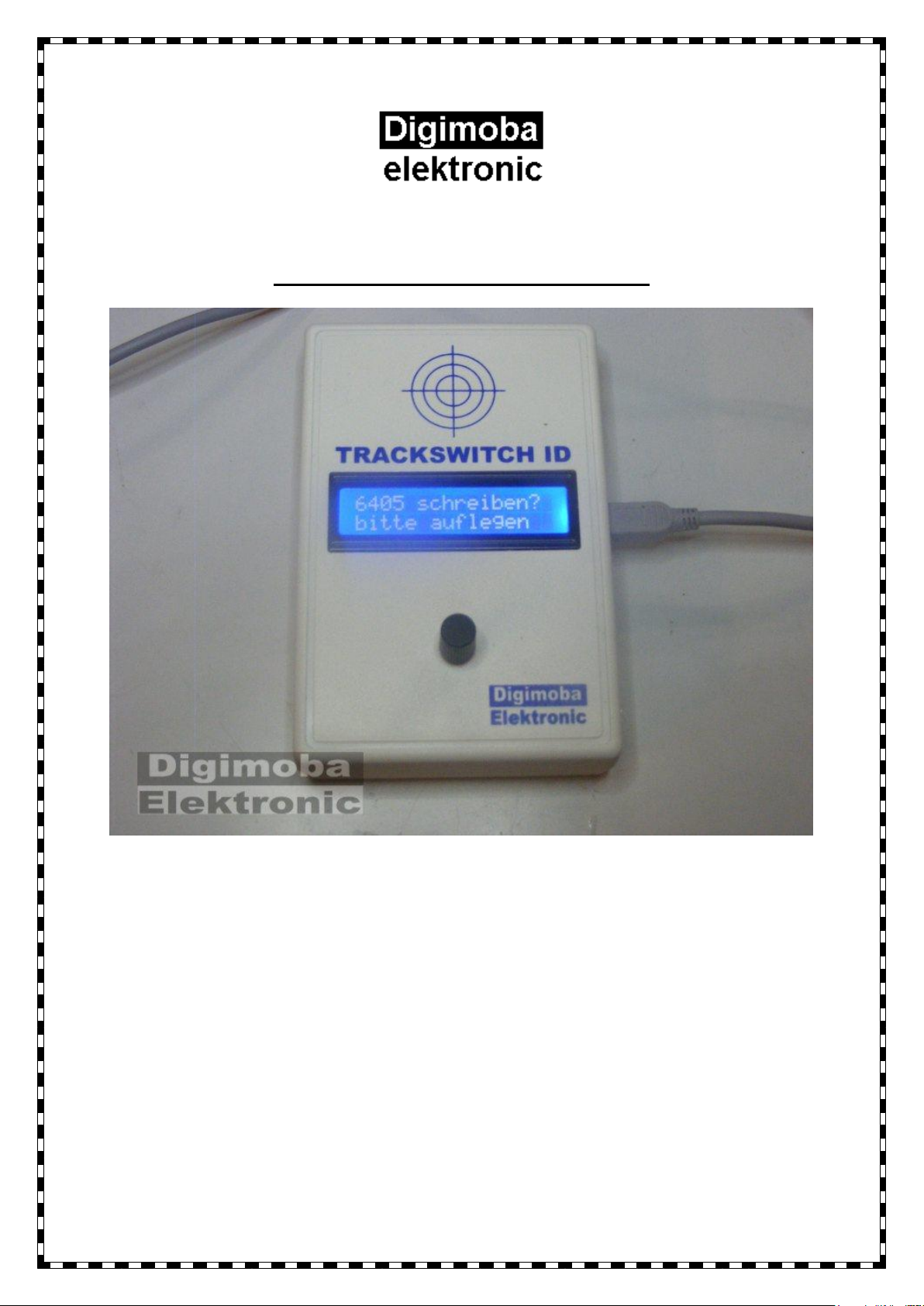
To write a suitable transponder (Tag) with the ID Manager 4000 select the menu
point “Transponder schreiben?” with the rotary encoder. Press the rotary knob briefly
to select the thousands digit. The desired number can be set by turning the rotary
knob. By pressing the rotary encoder, the next lower decimal point is reached to
select the next number until all numbers have been entered completely. Press twice
to dial the number with the question “Transponder schreiben? Bitte auflegen”
appears. Now the transponder must be held parallel on the surface on the marking of
the ID Manager. This number is written by pressing the rotary encoder again. You
can also stop the process by turning the knob counterclockwise. The display asks
you: “xxxx zurück?” xxxx stands for the selected number. By pressing the rotary
knob, you can start entering the number from the beginning without having written
this number, or by turning it clockwise you can return to the write query.
You can check whether the transponder has been correctly written by turning the
rotary encoder counterclockwise and display shows “Transponder lesen?” Hold the
transponder parallel to the surface above the marking. When the transponder has
3
been read out, the display changes to “Transponder gelesen:xxxx” for three seconds,
where xxxx stands for the number read out.
You can read out a transponder again or return to the menu for describing a
transponder by turning the rotary knob clockwise.
The transponders can be rewritten as often as required. Empty, still blank
transponders show 0000 when they are read out, can of course also be written in this
way again.
The ID Manager is powered by a USB mini cable from a standard USB charger that
can be plugged into the side of the unit. Bothe is included in the scope of delivery.
The device can be updated via this USB connection and is therefore prepared for
future innovations or expansions.
The appropriate transponders can be obtained from us. The mounting on or in the
vehicles is unproblematic with two exceptions:
1. They must not be glued directly onto or behind metallic substrates. Metal of
such magnitudes interferes with radio signals and makes there use
impossible. Tests have shown that the distance between a transponder and a
metal surface must be at least 10 mm.
2. The transponder must be placed as close as possible to the reader. So
underside of a vehicle or inside on the underside if the reader is mounted
under the track. Normal rails of a track limit the function only insignificantly.
Depending on the size of the transponder, distance of 15----35 mm are
possible.
The reader module 4010 consists of the actual module (blue) and the associated
electronics. A coded 8-pole cable (enclosed) connects these two elements. The
reading unit can easily be mounted under the desired track, and the function is also
available under the track substructure. Therefore, retrofitting existing plants is
relatively easy. Also here no metallic layers or foils should be present between
vehicle transponder and reader.
The transponder technology can be used independently of the many different current
systems and track gauges, whether analogue or digital. The mounting of
transponders on model vehicle as well as the installation of readers under a track is
relatively easy. The biggest advantage of this technology is that the existing electrical
systems do not have to be interfered with. Track separations or track contacts are
also not necessary! In addition, no special knowledge is required to use this
technology.
Legal information:
This device is exclusively approved for the intended use in dry rooms. The power
supply may only be providing from specially designed, approved and marked sources
for model railways applications.
Not technical changes may be made to the power supply or to our device be
unauthorized persons. Any liability for improper use or unauthorized modification is
rejected.
Reading this operating instruction is part of the intended use and is therefore
necessary before using our device.
Not suitable for children under the age of 14.
4
Stand 08/2019
Änderungen im Sinne des technischen Fortschrittes
vorbehalten.
Elektroaltgeräte gehören nicht in den Hausmüll! Bitte
entsorgen Sie diese kostenfrei bei Ihrem örtlichen
Entsorgungsunternehmen.
Digimoba Elektronic
Sudetenstraße 10
D-96253 Untersiemau
Tel.: 09565 488423
Fax.: 09565 488432
Ust-Id.Nr: DE814201353
WEEE-Nr : DE58841512
www.digimoba.de
Table of contents


