Digital Equipment RRD40 User manual

EK-RRD40-0M-001
RRD40
Optical
Disc
Drive
Owner's
Manual

EK-RRD40-0M-001
RRD40 Optical Disc Drive
Owner's
Manual
Prepared
by
Educational Services
of
Digital Equipment Corporation

September 1988
Copyright
ID1988
by Digital Equipment Cotporation.
All
Rights
Reserved.
Printed in U
.S.A
CLASS 1 DANGER
INVISIBLE LASER RADIATION
WHEN
OPEN.
AVOID DIRECT EXPOSURE TO BEAM
WARNING
Use
of
controls
and
adjustments
or
performance of procedures
other
than
those specified herein may result in hazardous radiation exposure.
NOTICE:
This equipment generates, uses, and may emit radio frequency energy. The
equipment has been type tested and found to comply with the limits for a
aass
A computing
device
pwsuant
to
Subpart
J
of
Part
15
of
FCC
Rule!!I,
which
are
designed
to
provide
reasonable
protection
against
such
radio
frequency
interference
when
operated
in a
commercial
environment Operation
of
this equipment in a residential area may cause interference
in
which
case
the
user
at
his
own
expense may
be
required
to talce
measures
to
correct
the
interference.
The information in this document is subject to change without notice and should not
be
construed
as a commitment
by
Digital Equipment Cotporation.
Digit81 Equipment Corporation assumes no responsibility for any errors that may appear in this
document.
The software,
if
any, described in this document is furnished under a license and may be used
or copied only
in
accordance with the terms
of
such license. No responsibility is assumed
for the use
or
reliability
of
software
or
equipment that is not supplied by Digital Equipment
Cotporation
or
its affiliated companies.
The following are trademarks
of
Digital Equipment Cotporation:
~amaamr
DEC
DECmailer
DECmate
DECnet
DECservice
DECsystem-I
0
DECSYSTEM-20
DECUS
DECwriter
DIBOL
MASSBUS
MicroVAX
MicroVAX II
MicroVAX 3000
PDP
P/OS
Professional
Q-Bus
Q22-Bus
Rainbow
RRD50
RSTS
RSX
RT
UNIBUS
VAX
VAXstation
VAXstation
II
VMS
VT
Worlc
Processor

Contents
1 Introduction
1.1
Scope . . . . . . . . . . . . . . . . . . . . . . . . . . . . . . . . . 1-1
1.2 Product Variations . . . . . . . . . . . . . . . . . . . . . . . . . . 1-1
1.2.l Drives . . . . . . . . . . . . . . . . . . . . . . . . . .
..
• . . .
1-2
1.2.2 Interfaces . . . . . . . . . . . . . . . . . . . . . . . . . . . . .
1-3
1.3 Specifications . . . . . . . . . . . . . . . . . . . . . . . . .
1-4
2 Installation
2.1
2.1.l
2.1.2
2.1.3
2.2
2.2.l
2.2.2
2.2.3
2.2.4
2.2.5
2.2.6
Half-Height RRD40 Installation . . . . . . . . . . . . . . . . . .
Assigning a SCSI Address ID Number
...........
.
Cabling the Half-Height RRD40 . . . . . . . . . . . . . . . .
Testing the Half-Height RRD40 . . . . . . . . . . . . . . . .
Tabletop RRD40 Installation . . . . . . . . . . . . . . . . . . . .
Equipment
............................
.
Voltage Selecting . . . . . . . . . . . . . . . . . . . . . . . . .
Cabling the Tabletop RRD40 . . . . . . . . . . . . . . . . . .
Installing the Power Cord/Verifying Power . . . . . . . . . .
Assigning an Address ID/Unit Number
...........
.
Testing the Tabletop RRD40 . . . . . . . . . . . . . . . . . .
3 Operation
3.1
3.2
3.3
3.4
3.4.l
3.4.2
3.4.3
Front Panel
Loading a Disc . . . . . . . . . . . . . . . . . . . . . . . . . . . .
Unloading a Disc . . . . . . . . . . . . . . . . . .. . . . . . . . .
Disc and Caddy Repairing . . . . . . . . . . . . . . . . . . . . .
Removing the Disc from the Caddy . . . . . . . . . . . . . .
Cleaning a Disc . . . . . . . . . . . . . . . . . . . . . .
Replacing the Disc in the Caddy . . . . . . . . . . . . . . . .
2-1
2-2
2-4
2-4
2-4
2-4
2--0
2--0
2-10
2-10
2-11
3-1
3-2
3-3
3-5
3-6
3-9
3-9
Iii

iv Contents
4 Testing the RRD40
on
a MicroVAX
4.1
4.2
4.2.1
4.2.2
4.3
4.3.1
4.3.2
4.3.3
4.3.4
4.3.5
4.3.6
Rwming Tests on MicroVAX Host Systems
Customer Run Tests on a MicroVAX Host System
......
.
Equipment
............................
.
Running MDM: Customer Mode . . . . . . . . . . . . . . . .
Service Mode Testing on a MicroVAX Host System
.....
.
Equipment
............................
.
Running MDM: Menu/Command Line Mode . . . . . . . . .
Help
..............................
..
Tests
..............................
..
Running the Tests . . . . . . . . . . . . . . . . . . . . . . . . .
Error Reports . . . . . . . . . . . .
A Digital Repair Services
Figures
4-1
4-2
4-2
4-2
4-7
4-7
4-7
4-8
4-9
4-9
4-13
1-1 RRD40 Tabletop Drive . . . . . . . . . . . . . . . . . . . . . . .
1-2
1-2
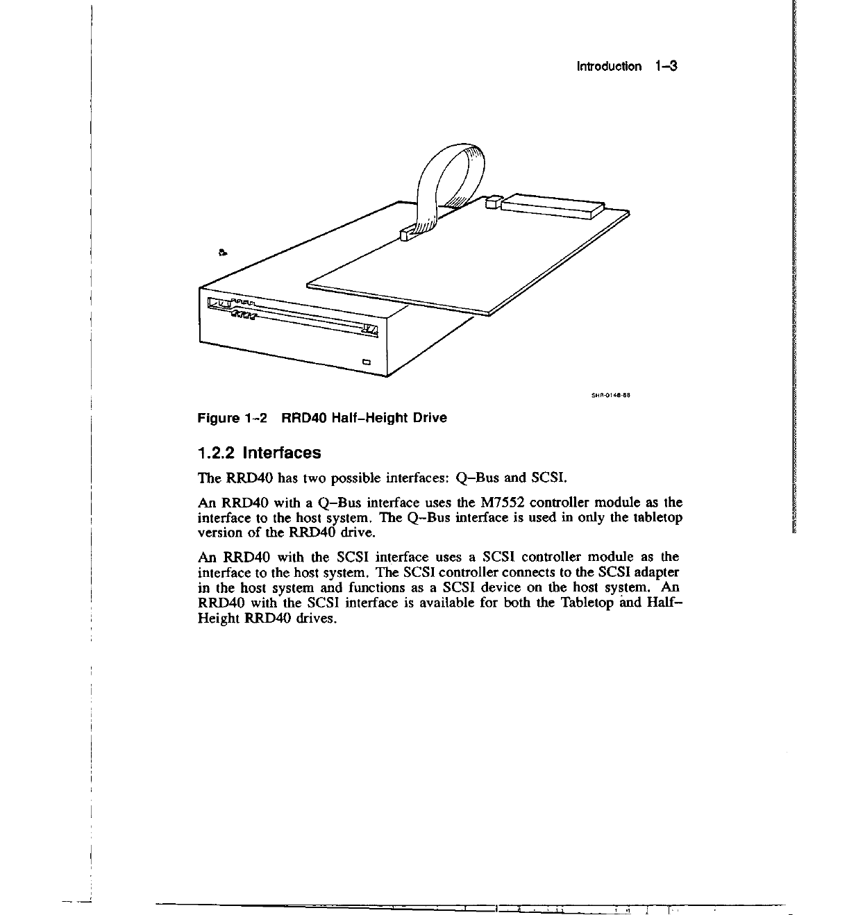
RRD40 Half-Height Drive . . . . . . . . . . . . . . . . . . . . .
1-3
2-1 SCSI Controller . . . . . . . . . . . . . . . . . . . . . . . . . . .
2-2
2-2
RRD40 Rear Panels . . . . . . . . . . . . . . . . . . . . . . . . .
2-5
2-3
Cabling:
Q-Bus
Interface . . . . . . . . . . . . . . . . . . . . . .
2-7
2-4
Cabling: I RRD40 with SCSI Interface . . . . . . . . . . . . .
2-8
2-5
Cabling: 2 RRD40s with SCSI Interface . . . . . . . . . . . . .
2-9
3-1 RRD40 Front Panel . . . . . . . . . . . . . . .
3-2
3-2
3-3
3-4
3-5
3-6
Disc Loading . . . . . . . . .
Caddy Parts . . . . . . . . . . . . . .
Disc Tabs
......................
.
Separating the Caddy . . . . . . . . . .
Separating the Disc and Housing . . . . . . . . .
3-4
3-5
3-6
3-7
3-8
I
I

Tables
1-1 RRD40 Specifications . . . . . . . . . . .
2-1
SCSI Address ID Nwnber Settings . . .
2-2
Tabletop RRD40 Installation: Parts List
4-1
Verify Mode Functional Tests . . . . . .
4-2
Service Mode Functional Tests
.......
.
4-3
Utilities . . . . . . . . . . . . . . . . . . . . .
4-4
Diagnostic Monitor: Set/Show Commands .
4-5
Drive Error Codes (Service Mode Only)
..
4-6
Controller Error Codes (Service Mode Only)
Contents V
1-4
2-3
2-5
4-5
4-6
4-6
4-11
4-14
4-15

1
Introduction
1.1
Scope
This manual
is
for the user and operator
of
the RRD40 Optical Disc Drive.
The RRD40
is
a read-only storage device that reads data stored on removable
optical discs. An optical disc
is
4.7 inches in diameter and can store 600
megabytes (about 600 million characters)
of
data.
In
optical storage devices, data (which
is
stored on the disc) is read off
of
the
disc by a laser system. A laser
is
a concentrated beam
of
light.
In
the RRD40,
the laser (contained in the RRD40 disc drive) shines light on the disc. The
intensity
of
the light reflected back (to the laser from the disc) determines the
data on the disc. The concentrated beam
of
light from the laser is so fine that
it
is
possible to store massive amounts
of
data on a single disc.
1.2 Product Variations
There are two RRD40 drives that use one
of
two interfaces.
1-1

1-2
Introduction
1.2.1 Drives
The RRD40
is
available as a tabletop version or a "half-height" version. The
half-height version
is
designed to be embedded into an existing host system
enclosure. Figure 1-1 and Figure
1-2
show the two RRD40 drives. Although
the two are physically different, they are functionally the same.
Figure 1-1 RRD40 Tabletop Drive

1-4
Introduction
1.3 Specifications
Table 1-1 gives the specifications
of
the RRD40 Disc Drive.
Table
1-1
RRD40 Specifications
PHYSICAL
Height:
Width:
Depth:
Weight:
PERFORMANCE
Capacity Per Disc:
Average Latency:
TABLETOP
76.2 mm (3.0 in)
229
mm
(9.125
in)
280
mm
(11.0 in)
4 kg (8.8 lb)
HALF-HEIGHT
41.5
mm
(1.6
in)
146 mm (5.75 in)
209 mm (8.07
in)
2 kg (4.4 lb)
635 megabytes
Average Transfer Rate:
155
msec at outer track
60 msec
at
inner track
175.2 Kbytes per second
Less than 6 secondsInitialization Startup Time:
ENVIRONMENTAL
OPERATING NON-OPERATING
Ambient Temperature:
10
to 50°C
-40
to
70°C
50 to 122°F 40 to 158°F
Relative Humidity:
10
to
80% 5
to
95%
Maximum
Wet
Bulb: 28°C (78°F) 46°C (115°F)
Max Pressure Altitude: 3.4
km
13.6
km
Heat Dissipation:
14
W (typical)

Introduction
1-3
SHA-0148·8!:1
Figure
1-2
RRD40
Half-Height
Drive
1.2.2 Interfaces
The RRD40 has two possible interfaces:
Q-Bus
and SCSI.
An RRD40 with a
Q-Bus
interface uses the M7552 controller module as the
interface to the host system. The
Q-Bus
interface is used in only the tabletop
version
of
the RRD40 drive.
An RRD40 with the SCSI interface uses a SCSI controller module as the
interface to the host system. The SCSI controller connects to the SCSI adapter
in the host system and functions as a SCSI device on the host system.
An
RRD40 with the SCSI interface is available for both the Tabletop and
Half-
Height RRD40 drives.
'
.,
i
I
I
I
!

2
Installation
This chapter gives instructions on how to install the RRD40 Disc Drive.
Most
of
the instructions deal with the installation
of
the Tabletop RRD40; the
installation
of
the Half-Height RRD40
is
covered briefly.
2.1 Half-Height RRD40 Installation
The Half-Height RRD40 comes with a SCSI interface only. This version
of
the drive
is
generally not customer installable. This section gives some
general installation information, but refer
to
the host system documentation
for specific installation instructions.
The installation
of
the Half-Height RRD40 into the host system unit
is
dependent on the system enclosure and also the current configuration
of
the
host system.
If
you are installing a Tabletop RRD40, go to Section 2.2.
2-1

2-2
Installation
2.1.1
Assigning a
SCSI
Address
ID
Number
Locate the switch pack on the SCSI controller module (refer
to
Figure 2-1).
The switch pack can be assigned any number
0-
7.
The four DIP switches on
the switch pack are numbered
1-4.
Switch 1 sets the most significant bit, and
switch 3 sets the least significant bit. Switch 4
is
unused. The board comes
preset
to
ID number 0 (all switches down).
ADDRESS
10
NUMBER SWITCH PACK
'----f'
n
~---
SH~-0149·88
Figure 2-1 SCSI
Controller

Installation
2-3
Proceed as follows:
1.
Determine the SCSI Address
ID
number that your RRD40 will be
assigned. This number is based on the current configuration
of
the
host system and can be any number
0-7.
Refer
to
your host system
documentation for more information on the SCSI Address
ID
numbers.
2. Set the switch pack to the correct
ID
number. Table 2-1 gives the
settings for each
of
the eight possible
ID
numbers that the controller can
be assigned. Use a ball point pen or pointed object to set the switches.
NEVER USE A PENCIL TO SET THE SWITCH PACK. The graphite
used
in
pencils can damage the switch pack.
Table
2-1
SCSI Address
ID
Number Settings
ID Number Binary Code Switch Settings
1 2 3 4
0 000 0 0 0 0
I 001 0 0 I 0
2 010 0 I 0 0
3
011
0 I I 0
4 100 I 0 0 0
5 IOI I 0 I 0
6 110 I I 0 0
7
Ill
I I I 0
Key
to
Switch Settings
0=0N=UP
I=
OFF=
DOWN
Switch 4 must be set to 0

2-4
Installation
2.1.2 Cabling the Half-Height RRD40
The Half-Height RRD40
is
embedded inside the host system enclosure and
is
cabled internally. Refer to the host system documentation.
2.1.3 Testing the Half-Height RRD40
The Half-Height RRD40 uses a SCSI interface and responds to the same
testing as the other SCSI devices on the host system. Refer to the host system
documentation.
2.2 Tabletop RRD40 Installation
The Tabletop RRD40 comes with either a
Q-Bus
or SCSI interface. The
RRD40 rear panels are different for each interface, but the installation
procedures are similar. Figure
2-2
shows both rear panels.
The RRD40 with the
Q-Bus
interface has only one cable connector on the
rear panel. The RRD40 with the SCSI interface has two cable connectors
on
the rear panel. There are two cable connectors because SCSI RRD40's can
be "daisy-chained" together. Refer to Section 2.2.3 for more information on
the cable connectors.
2.2.1
Equipment
The equipment necessary to install the Tabletop RRD40 depends on which
interface (SCSI or
Q-Bus)
your RRD40 uses. Table
2-2
lists the parts
needed for each installation. Make sure that you have all parts necessary for
installation before proceeding.
Note that
if
your RRD40 uses the
Q-Bus
interface, the M7552 controller
module should have already been installed into the host system by a specially
trained Digital Field Service Engineer.

0-BUS
INTERFACE
~\·.-
............
l@I
(~
a-BUS
INTERFACE
CABLE
CONNECTOR
SCSI
INTERFACE
SCSI
UNIT
NUMBER SWITCH PACK
SCSI
INTERFACE
CABLE
CONNECTORS
Figure
2-2
RRD40 Rear Panels
Installation
2-5
POWER SWITCH
o==
VOl
TAGE SELl;;CTOR
SHR-0139·88
VOLTAGE
SELECTOR
Table
2-2
Tabletop RRD40 Installation: Parts List
Equipment
External
1/0
Cable
Part Number
BC18R-XX
or
BC16V-XX
17-02007-01
Power Cord n/a
Test Disc 23507-03
M7552 Controller Kit KRQ50-xx
SCSI Interface
Q-Bus
Ioterface
..;
..;
..;
..;
..;
..;

2-6
Installation
2.2.2 Voltage Selecting
The rear panel
of
the RRD40 contains a voltage selector that can
be
set to
one
of
two voltages (110 V or 220 V). Figure
2-2
shows the location
of
the
selector on the rear panel. Verify
that
the
voltage
that
your
RRD40
is
set
to is
the
correct
voltage
for
your
power
requirements
before powering
up
the
drive.
To change the setting
of
the voltage selector, insert a flat object (such as a
screwdriver) into the selector and turn so the desired voltage
is
facing up.
In
Figure
2-2,
the selected voltage is 110
V.
2.2.3 Cabling the Tabletop RRD40
The cabling is different depending on which interface your RRD40 uses. The
Q-Bus
interface is a simple connection from the rear of the drive to the host
system. The SCSI interface requires a terminator assembly.
0-Bus
Interface
The cabling for the
Q-Bus
interface depends on the host system.
Some host systems (such as the MicroVAX 3000 series) have a cable
connected directly to the controller module in the host system. This cable
comes out
of
the rear
of
the host system and must be installed into the
interface connector on the rear
of
the RRD40 drive. The cable
is
tightened
onto the connector by hand. The rear panel
of
the RRD40 drive
is
shown in
Figure 2-2.
Other host systems (such
as
the MicroVAX II) have an RRD40 bulkhead on
the rear patch panel
of
the system. This bulkhead has two connectors marked
"A" and "B".
If
this
is
the first RRD40 to be attached to the controller, then
you would attach the cable to the "A" connector. The cable
is
tightened onto
the connector by hand at both ends. Connect the cable to the host system
first, and then to the rear
of
the RRD40 drive. The cabling
is
shown in
Figure
2-3.

lnslallation
2-7
Figure
2-3
Cabling:
0-Bus
Interface
SCSI Interface
An RRD40 which uses the SCSI interface has two cable connectors on the
rear panel (shown in Figure 2-2). The SCSI interface allows for connecting
multiple drives in a daisy-chain configuration. Because
of
this option, the
final drive in the chain must be "terminated". The terminator is simply a
connector for the unused rear panel interface connector on the drive.
It
is the
same as the connector on the I/O cable.
If
you have only one drive, the external
I/0
cable is connected from the host
system to the top connector on the RRD40 drive. The terminator is then
installed in the bottom connector on the rear panel
of
the drive.
If
you have a second RRD40 drive, the external I/O cable for drive #2 goes
from the bottom connector
of
drive
#1
to the top connector
of
drive #2. The
terminator is then installed into the bottom connector on the rear panel
of
drive #2.
Follow the applicable instructions.

2~
Installation
Single
drive
cabling
To
cable a single drive, proceed as follows (refer
to
Figure
2-4
):
l.
Connect the external 1/0 cable
to
the SCSI port on the rear
of
the host
system.
2.
Connect the other end
of
the cable
to
the top connector on the rear
of
the
drive.
3.
Install a terminator assembly into the unused (bottom) connector on the
rear
of
the RRD40.
Figure
2-4
Cabling: 1 RRD40
with
SCSI Interface
11
I
I
I
"
I
I
'

Installation
2-9
Multiple drive cabling
If
you already have an RRD40 drive on the
system, and you want to add another RRD40, then a "daisy-chain" cabling
configuration
is
used.
To
daisy-chain a drive is to connect the new drive to
the RRD40 that is already connected to the host system.
To daisy-chain a new drive to a previously connected drive, proceed as
follows (refer to Figure 2-5):
1. Remove the terminator from the bottom connector
of
the RRD40 that is
already connected to the host system.
2. Take the external I/O cable for the RRD40 drive that you are installing.
Install one end into the open connector (the connector that you just
removed the terminator from).
3. Install the other end
of
the I/O cable into the top connector
of
the "new"
RRD40 (the drive that you are installing).
4. Install the terminator into the unused (bottom) interface connector on the
RRD40 you are installing.
TERMINATOR
Figure
2-5
Cabling: 2 RRD40s with SCSI Interface

2-10
Installation
2.2.4 Installing the Power Cord/Verifying Power
1.
Make sure that the power switch on the rear panel
of
the RRD40 is set
to the OFF (0) position (refer to Figure 2-2).
2. Install the female end
of
the power cord into the receptacle on the rear
of
the drive.
3. Install the other end
of
the power cord into a wall outlet rated for the
correct voltage. Make sure the voltage selector is properly set.
4. Tum the rear panel power switch to the ON
(I)
position and verify that
the POWER indicator on the front panel lights.
If
the POWER indicator does not light, then a problem exists. Set the
POWER switch back to the OFF (0) position. Verify that the wall outlet
has power, and try again.
If
the indicator still fails to light, contact your
Digital Service Representative before proceeding any further.
2.2.5 Assigning
an
Address ID/Unit Number
For the SCSI interface, you must assign the drive a SCSI Address ID number.
For the
Q-Bus
interface, you must assign the drive a unit number. Follow the
instructions that apply.
SCSI Interface
Locate the switch pack on the rear
of
the SCSI Tabletop RRD40 (shown in
Figure 2-2). This switch pack sets the SCSI Address ID number that the
RRD40 will respond
to
in
the host system. The drive must be given a SCSI
Address ID number by setting the switch pack. The four DIP switches on
the switch pack are numbered
1-4.
Switch I sets the most significant bit, and
switch 3 sets the least significant bit. Switch 4 is unused. The board comes
preset to Address ID number 0 (all switches down).
Proceed as follows:
I. Power down the drive.
2.
Determine the SCSI Address ID number that your RRD40 will be
assigned. This number
is
based on the current configuration
of
the
host system and can be any number
0-7.
Refer to your host system
documentation for more information on the SCSI Address ID numbers.
Table of contents
Other Digital Equipment DVD Drive manuals
Popular DVD Drive manuals by other brands

NEC
NEC ND-3520A user manual

Dolby Laboratories
Dolby Laboratories Program Optimizer DP600 Replacement guide

Toshiba
Toshiba PA3352 1CD2 Series user guide

Ikebana
Ikebana USB 2.0 External DVD-R/RW Quick Start Installation Guide for Windows PC

IBM
IBM 10K3799 user guide

Lenovo
Lenovo ThinkPad Ultrabay 9.5-mm DVD Burner IV user guide