Digitrax DZ125IN User manual

DZ125IN
Fits Many N Locomotives
F
Fe
ea
at
tu
ur
re
es
s:
:
nPlug N’Play decoder: for 6-pin socket N scale locomotives
nDigitrax LocoMotion®System-Your locomotives look like the real thing.
The Digitrax LocoMotion System makes them run like the real thing, too!
Torque Compensation for smooth as silk silent operation.
128 Speed Step operation (14 or 28 steps can also be used).
Momentum with acceleration and deceleration.
Normal Direction of Travel is user selectable.
Switching Speed feature for easier and faster access to yard speeds.
3 Step Speed Tables set start, mid and max voltage for custom control.
28 Step Speed Tables with 256 level resolution for precise control.
nScaleable Speed Stabilization (Back EMF) with simple setup & 256 level
resolution.
nSuperSonic motor drive for silent operation.
nFX3Function outputs for prototypical lighting effects and on/off control:
Constant Brightness Lighting with directional or independent control.
Realistic Effects like Ditch lights, Mars lights, strobes, and many more.
FX3 & Standard Function Qualifiers operate functions based on direction,
F0 on or off, direction and F0, and whether loco is moving.
Function Remapping of 14 functions for custom function setup.
Master Light Switch turns off all lights & functions with one keystroke.
nTransponder ID Equipped ready for transponding on your Layout, for e.g.
a Digital surround-sound system
nAll Mode Programming
nDecoder Reset CV with or without speed table reset.
nMotor Isolation Protection prevents damage to your decoder.
nBasic, Advanced & UniVersal Consisting
n2 Digit and 4 Digit Addressing
nUp to 20V DCC/DC track voltage operation, maximum
nDCC Compatible
©2007 Digitrax, Inc www.digitrax.com 1
N Scale
Mobile Decoder
1 Amp/1.25 Amp Peak
2 FX3Functions, 0.5 Amp
with 6 Pin NEM 651 type plug fit Kato
N-EMD class 66 and others
D
Di
ig
gi
it
tr
ra
ax
xC
Co
om
mm
ma
an
nd
dC
Co
on
nt
tr
ro
ol
l
R
Ru
un
nY
Yo
ou
ur
rT
Tr
ra
ai
in
ns
s,
,N
No
ot
tY
Yo
ou
ur
rT
Tr
ra
ac
ck
k!
!

©2007 Digitrax, Inc www.digitrax.com 2
P
Pa
ar
rt
ts
sL
Li
is
st
t
1 DZ125IN Decoder 1 Instruction sheet
I
In
ns
st
ta
al
ll
la
at
ti
io
on
nI
In
nf
fo
or
rm
ma
at
ti
io
on
n
See the Digitrax Decoder Manual for complete decoder test procedures, instal-
lation instructions, programming and technical information. Digitrax manuals
and instructions are updated periodically. Please visit www.digitrax.com for the
latest versions, technical updates and available locomotive-specific installation
instructions.
I
In
ns
st
ta
al
ll
la
at
ti
io
on
nI
In
ns
st
tr
ru
uc
ct
ti
io
on
ns
s
1. Carefully remove the locomotive’s shell from the frame. Notice the orienta-
tion of the shell to the frame so that you can reinstall correctly.
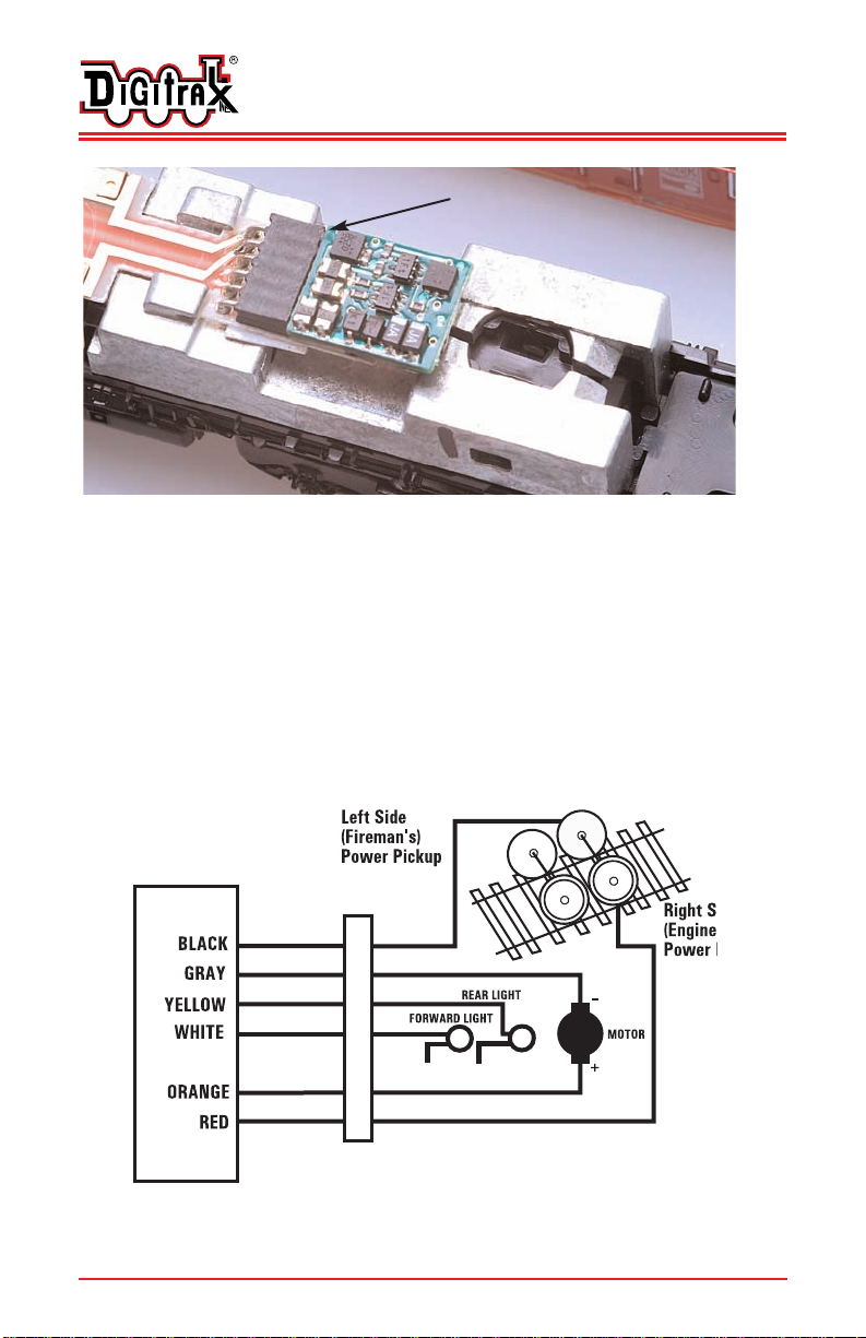
2. Remove the 6 pin analog shorting plug and in its place insert the DZ125IN
decoder with the correct pin-1 orientation. The DZ125IN has 6 pins that
insert directly into the 6 pin socket (NEM 651 type) on the locomotive’s
PCB. The DZ125’s small size allows the decoder to be easily installed in a
variety of European locomotives. For the Kato EMD Class 66 example, the
DZ125IN should be inserted in the socket as shown in Figure 2.
(Figure 1): Kato factory N-EMD class 66
D
Di
ig
gi
it
tr
ra
ax
xC
Co
om
mm
ma
an
nd
dC
Co
on
nt
tr
ro
ol
l
R
Ru
un
nY
Yo
ou
ur
rT
Tr
ra
ai
in
ns
s,
,N
No
ot
tY
Yo
ou
ur
rT
Tr
ra
ac
ck
k!
!
PIN 1
Factory Analog
shorting plug
©2007 Digitrax, Inc www.digitrax.com 3
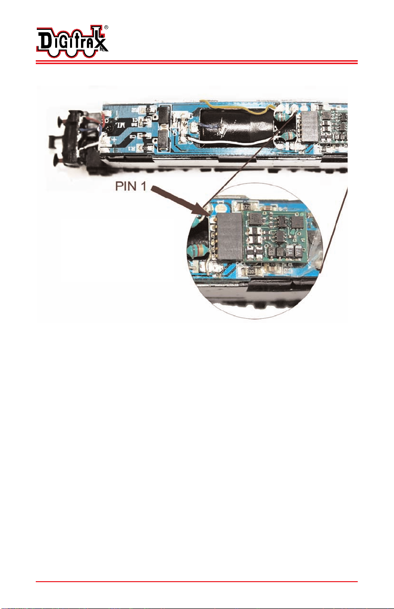
(Figure 2): Kato N-EMD class 66 with DZ125IN installed
3. Test the locomotive on some track with a DCC system to verify motor and
lights work in both directions
4. Reinstall the locomotive’s shell , install is complete!
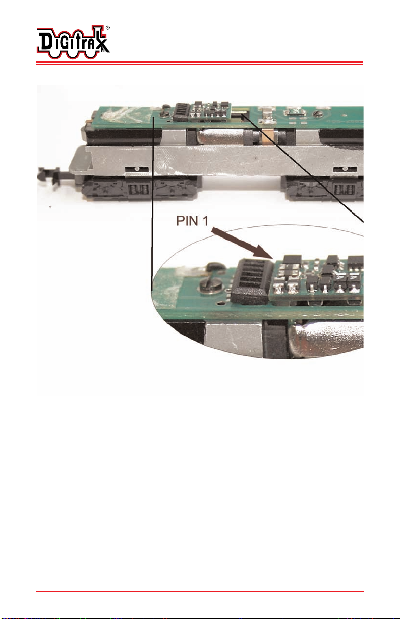
For proper installation orientation in Bachmann Farish Jubilee, the Dapol
Hymek and the Trix v160 N scale examples, please refer to page 9 in
this guide. For other N scale locomotives be sure to identify the correct pin-
1 location of the locomotive socket from the manufacturer’s instructions.
4
45
50
0C
Ce
em
me
et
te
er
ry
yS
St
tr
re
ee
et
tT
T7
77
70
0-
-4
44
41
1-
-7
79
99
92
2
N
No
or
rc
cr
ro
os
ss
s,
,G
GA
AU
US
SA
A3
30
00
07
71
1F
F7
77
70
0-
-4
44
41
1-
-0
07
75
59
9
w
ww
ww
w.
.d
di
ig
gi
it
tr
ra
ax
x.
.c
co
om
mE
Es
sa
al
le
es
s@
@d
di
ig
gi
it
tr
ra
ax
x.
.c
co
om
m
DZ125IN
Pin 4
Pin 2
Pin 6
Pin 5
Pin 1
Pin 3
NEM 651 loco socket
Figure 3. DZ125IN Wiring Diagram
Warning: to prevent decoder
damage, the decoder must be
correctly oriented in the socket
PIN 1
©2007 Digitrax, Inc www.digitrax.com 4
DZ125IN is factory default programmed to address 03. You can easily cus-
tomize the address and other features. See section “Customizing Your
Decoder” that
Installation Notes:
1. Do not exceed the decoder’s 500mA total function output rating.
2. We recommend that the Blue wire, also called +Common or Lamp
Common, be connected as shown. If you wish to omit the Blue wire in your
installation, consult the Digitrax Decoder Manual for more information.
3. The head lamp should be hooked up using the Blue/+Common wire for
optimal Digitrax transponding operation.
4. To use a function output with an inductive (coil) type load, see the Digitrax
Decoder Manual for more information to avoid damage to the decoder.
5. See the Digitrax Decoder Manual for full details of wiring 12-16V lamps,
1.5V lamps, and LEDs. Lamps that draw more than 80 mA when running
require a 22 ohm 1/4 watt resistor in series with the directional light func-
tion lead to protect the decoder.
6. Some locomotives employ filter capacitors for RFI suppression in the loco-
motive wiring. These may cause problems with Supersonic decoders and
non-decoder analog operation on DCC. This capacitor should be removed
for safe operation.
C
Cu
us
st
to
om
mi
iz
zi
in
ng
gY
Yo
ou
ur
rD
De
ec
co
od
de
er
r
Your Digitrax decoder is ready to run and will operate using address 03 with no
additional programming. For a more prototypical railroading experience, your
decoder can be customized for your specific locomotive by programming some
of the Configuration Variables, or CVs, available. See the Digitrax Decoder
Manual or the Digitrax web site for more information.
C
Ch
ha
an
ng
gi
in
ng
gt
th
he
eD
De
ec
co
od
de
er
rA
Ad
dd
dr
re
es
ss
s
The first CV most people change is the decoder address. This allows you to
D
Di
ig
gi
it
tr
ra
ax
xC
Co
om
mm
ma
an
nd
dC
Co
on
nt
tr
ro
ol
l
R
Ru
un
nY
Yo
ou
ur
rT
Tr
ra
ai
in
ns
s,
,N
No
ot
tY
Yo
ou
ur
rT
Tr
ra
ac
ck
k!
!
Loco Type V Start V Mid V Max
CV02 CV06 CV05
Switcher
Concentrated low speed. Limited top 002/x02 038/x26 064/x50
speed
Road Switcher
Prototypical top speed w/evenly 002/x02 048/x30 098/x62
distributed curve from 0 to top speed
Mainline Loco
Quick increase to cruising speed then 002/x02 128/x80 154/x9A
levels off to prototypical top speed.

©2007 Digitrax, Inc www.digitrax.com 5
independently control each loco with a unique address. Digitrax decoders are
shipped with CV01 (AD2), the two digit address, set to 03. Following is a brief
description of how to change the decoder address with a Digitrax DT series
throttle. See your Starter Set Manual for complete programming instructions.
1 Place the loco on the programming track. Go into Program Mode on your
system. On DT400 press PROG. On DT300, DT100 & DT200 press
RUN/STOP & FN/F0.
2. Choose AD2 for 2 digit addressing or AD4 for 4 digit addressing (DT300 &
DT400). (Ad for DT100 & DT200, see your Starter Set manual for 4 digit
instructions).
3. Use your throttle to choose the address you want to set up for the decoder.
4. Complete address programming. On DT400 press ENTER. On DT300,
DT100 & DT200 press SEL.
Note: CV29 must also be programmed to enable 4 digit addressing, this is
done automatically by the DT300 & DT400 but not on earlier throttles.
4
45
50
0C
Ce
em
me
et
te
er
ry
yS
St
tr
re
ee
et
tT
T7
77
70
0-
-4
44
41
1-
-7
79
99
92
2
N
No
or
rc
cr
ro
os
ss
s,
,G
GA
AU
US
SA
A3
30
00
07
71
1F
F7
77
70
0-
-4
44
41
1-
-0
07
75
59
9
w
ww
ww
w.
.d
di
ig
gi
it
tr
ra
ax
x.
.c
co
om
mE
Es
sa
al
le
es
s@
@d
di
ig
gi
it
tr
ra
ax
x.
.c
co
om
m

©2007 Digitrax, Inc www.digitrax.com 6
D
Di
ig
gi
it
tr
ra
ax
xL
Lo
oc
co
oM
Mo
ot
ti
io
on
n
®
S
Sy
ys
st
te
em
m
Your locomotives look like the real thing, now you can make them run like the
real thing, too. Digitrax decoders incorporate torque compensation for smooth
as silk operation. You can also program CVs that control momentum, 3 step
and 128 step speed tables, switching speed, normal direction of travel and more
to take full advantage of the Digitrax LocoMotion System.
M
Mo
om
me
en
nt
tu
um
m-
-C
CV
V0
03
3&
&C
CV
V0
04
4
Momentum is part of the LocoMotion System. Acceleration is controlled by
CV03 and deceleration by CV04. Both come from the factory set to 000/x00. A
range of 000/x00 to 031/x1F is available for both accel and decel. We recom-
mend that you try CV03:003/x03 and CV04:000/x00 as a starting point for
experimenting with momentum.
S
Sp
pe
ee
ed
dT
Ta
ab
bl
le
es
s-
-H
Ho
ow
wt
th
he
eL
Lo
oc
co
oR
Re
es
sp
po
on
nd
ds
st
to
ot
th
he
eT
Th
hr
ro
ot
tt
tl
le
e
With Digitrax LocoMotion, there are two types of speed tables: 3 Step Tables
and High Resolution 28 Step Tables. Please see your Digitrax Decoder Manual
for a discussion of the 28 Step Tables. The 3 Step Tables are set up by program-
ming 3 CVs: Start Voltage (CV02), Mid point Voltage (CV06) and Max Voltage
(CV05). These values are set at 000/x00 at the factory. All have a range of val-
ues from 000/x00 to 255/xFF. We recommend the following CV values as a
starting point for experimenting with speed tables.
D
Di
ig
gi
it
tr
ra
ax
xC
Co
om
mm
ma
an
nd
dC
Co
on
nt
tr
ro
ol
l
R
Ru
un
nY
Yo
ou
ur
rT
Tr
ra
ai
in
ns
s,
,N
No
ot
tY
Yo
ou
ur
rT
Tr
ra
ac
ck
k!
!

©2007 Digitrax, Inc www.digitrax.com 7
O
Ot
th
he
er
rL
Lo
oc
co
oM
Mo
ot
ti
io
on
n
®
F
Fe
ea
at
tu
ur
re
es
s:
:S
Sw
wi
it
tc
ch
hi
in
ng
gS
Sp
pe
ee
ed
d&
&N
No
or
rm
ma
al
lD
Di
ir
re
ec
ct
ti
io
on
n
o
of
fT
Tr
ra
av
ve
el
l
Switching speed is controlled by CV54. The factory setting is 000/x00 for
OFF. To turn on the switching speed feature, program CV54 to a value of
001/x01. When this feature is on, use F6 to activate and deactivate switching
speed. When switching speed is ON and F6 is ON, the switching speed feature
is on. With the feature ON, the throttle’s target speed is effectively reduced by
about 50% and the effects of accel and decel programmed into the decoder are
reduced by 1/4. This is useful for yard switching operations.
Normal Direction of Travel is controlled by CV29. See your decoder manual
for additional information on the settings for CV29.
This decoder supports Scaleable Speed Stabilization (Back EMF)
S
Su
up
pe
er
rS
So
on
ni
ic
cS
Si
il
le
en
nt
tO
Op
pe
er
ra
at
ti
io
on
na
an
nd
dT
To
or
rq
qu
ue
eC
Co
om
mp
pe
en
ns
sa
at
ti
io
on
n
The factory settings in the decoder provide silent, smooth operation of your
locomotive under most conditions. For more information about these settings,
please see the Digitrax Decoder Manual or our website.
D
Di
ig
gi
it
tr
ra
ax
xT
Tr
ra
an
ns
sp
po
on
nd
di
in
ng
gC
CV
V6
61
1
Digitrax Transponding is controlled by CV61. The initial factory set value is
000/x00 for OFF. To turn ON transponding, program CV61 to a value of
002/x02. This allows you to use Digitrax transponding to keep track of your
rolling stock. When transponding is enabled, the front light of the locomotive
will flicker slightly to indicate transponding signal is being communicated. For
optimal transponding operation, we recommend that you hook up the forward
and rear lights as shown in the wiring diagram (Figure 1).
D
De
ec
co
od
de
er
rR
Re
es
se
et
tC
CV
V0
08
8
Decoder reset lets you reset all CV values to the initial factory settings. To
reset all CV values, program CV08 to a value of 008/x08. You also have the
option of resetting all values except the 28 speed step tables. To do this, pro-
gram CV08 to a value of 009/x09.
4
45
50
0C
Ce
em
me
et
te
er
ry
yS
St
tr
re
ee
et
tT
T7
77
70
0-
-4
44
41
1-
-7
79
99
92
2
N
No
or
rc
cr
ro
os
ss
s,
,G
GA
AU
US
SA
A3
30
00
07
71
1F
F7
77
70
0-
-4
44
41
1-
-0
07
75
59
9
w
ww
ww
w.
.d
di
ig
gi
it
tr
ra
ax
x.
.c
co
om
mE
Es
sa
al
le
es
s@
@d
di
ig
gi
it
tr
ra
ax
x.
.c
co
om
m

©2003 Digitrax, Inc www.digitrax.com 8
F
Fu
un
nc
ct
ti
io
on
nO
Ou
ut
tp
pu
ut
ts
so
on
nt
th
he
eD
DZ
Z1
12
25
5I
IN
N
The DZ125IN is set up at the factory to control two function outputs. The
DZ125IN is configured to control the forward and reverse lights on the loco-
motive through the white lead and yellow lead using Function 0 (F0F-forward
and F0R-reverse) for directional lighting. Both function outputs can be easily
set up with Digitrax FX3lighting effects or as standard on/off functions with
the following operational qualifiers:
1. Forward or Reverse direction of travel, or
2. Whether F0 is on or off, or
3. Both direction of travel and whether F0 is on or off, or
4. Whether the locomotive is stopped or moving.
M
Ma
as
st
te
er
rL
Li
ig
gh
ht
tS
Sw
wi
it
tc
ch
h
Each of the function outputs can be programmed to turn on and off with the F0
ON/OFF key on your throttle, creating a Master Light Switch. The CV
values for creating this effect are listed in the Digitrax Decoder Manual in the
section: Setting Up FX & FX3Effects on Function Outputs.
W
Wa
ar
rr
ra
an
nt
ty
y&
&R
Re
ep
pa
ai
ir
r
All warranties on Digitrax products are limited to refund of purchase price,
repair or replacement at Digitrax’s sole discretion. Except as expressly stated in
the full warranty statement, there are no warranties, express or implied, includ-
ing but not limited to any warranties of merchantability or fitness for a particu-
lar purpose. This decoder is not warrantied for track voltages above +/- 20V in
DCC or DC operation. Be sure to check your DCC or DC system does not cre-
ate voltages on the tracks above this limit. For complete warranty details see
www.digitrax.com.
Digitrax, Inc. is not responsible for unintentional
errors or omissions in this document.
D
Di
ig
gi
it
tr
ra
ax
xC
Co
om
mm
ma
an
nd
dC
Co
on
nt
tr
ro
ol
l
R
Ru
un
nY
Yo
ou
ur
rT
Tr
ra
ai
in
ns
s,
,N
No
ot
tY
Yo
ou
ur
rT
Tr
ra
ac
ck
k!
!

©2003 Digitrax, Inc www.digitrax.com 9
4
45
50
0C
Ce
em
me
et
te
er
ry
yS
St
tr
re
ee
et
tT
T7
77
70
0-
-4
44
41
1-
-7
79
99
92
2
N
No
or
rc
cr
ro
os
ss
s,
,G
GA
AU
US
SA
A3
30
00
07
71
1F
F7
77
70
0-
-4
44
41
1-
-0
07
75
59
9
w
ww
ww
w.
.d
di
ig
gi
it
tr
ra
ax
x.
.c
co
om
mE
Es
sa
al
le
es
s@
@d
di
ig
gi
it
tr
ra
ax
x.
.c
co
om
m
©2003 Digitrax, Inc www.digitrax.com 10
4
45
50
0C
Ce
em
me
et
te
er
ry
yS
St
tr
re
ee
et
tT
T7
77
70
0-
-4
44
41
1-
-7
79
99
92
2
N
No
or
rc
cr
ro
os
ss
s,
,G
GA
AU
US
SA
A3
30
00
07
71
1F
F7
77
70
0-
-4
44
41
1-
-0
07
75
59
9
w
ww
ww
w.
.d
di
ig
gi
it
tr
ra
ax
x.
.c
co
om
mE
Es
sa
al
le
es
s@
@d
di
ig
gi
it
tr
ra
ax
x.
.c
co
om
m
Installation orientation
for Dapol Hymek
©2003 Digitrax, Inc www.digitrax.com 11
4
45
50
0C
Ce
em
me
et
te
er
ry
yS
St
tr
re
ee
et
tT
T7
77
70
0-
-4
44
41
1-
-7
79
99
92
2
N
No
or
rc
cr
ro
os
ss
s,
,G
GA
AU
US
SA
A3
30
00
07
71
1F
F7
77
70
0-
-4
44
41
1-
-0
07
75
59
9
w
ww
ww
w.
.d
di
ig
gi
it
tr
ra
ax
x.
.c
co
om
mE
Es
sa
al
le
es
s@
@d
di
ig
gi
it
tr
ra
ax
x.
.c
co
om
m
Installation
orientation for
Trix V 160

Made in U.S.A.
307-DZ125IN-INS 1k/11/07
DZ125IN
Fits a Variety of N Scale Locomotives
450 Cemetery Street
Norcross, GA USA 30071
www.digitrax.com
T770-441-7992
F770-441-0759
Other Digitrax Toy manuals

Digitrax
Digitrax SoundFX SDH187MT User manual

Digitrax
Digitrax Evolution Express Series User manual

Digitrax
Digitrax LocoMotion DN163K0b User manual

Digitrax
Digitrax Zephyr Express DCS52 User manual

Digitrax
Digitrax Super Chief Xtra DT402 Series User manual

Digitrax
Digitrax DN166I2B User manual

Digitrax
Digitrax DN136D User manual

Digitrax
Digitrax UP7 User manual

Digitrax
Digitrax DN166I0 User manual
Popular Toy manuals by other brands

REVELL
REVELL KIT 0302 Assembly manual

Barbie
Barbie POWER WHEELS P5066 Owner's manual & assembly instructions

Eduard
Eduard Spitfire F Mk.IX manual

Multiplex
Multiplex Space Scooter Building instructions

MiniArt
MiniArt WW II Military Miniatures Series General Instruction

Mega Construx
Mega Construx Call of Duty DPB56 instructions


