Digitronic Digitaler Schaltbeschleuniger
Automationsanlagen GmbH DIGISPEEDDS1/V2
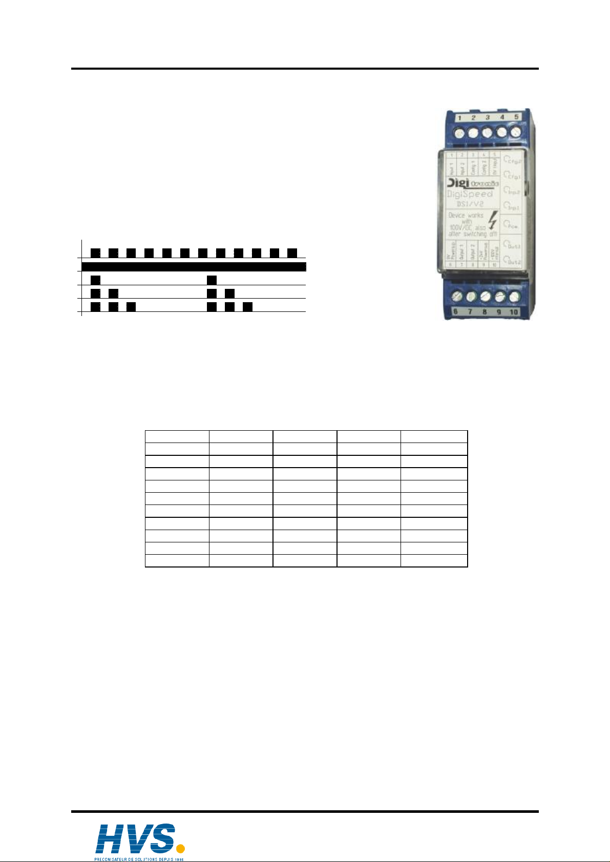
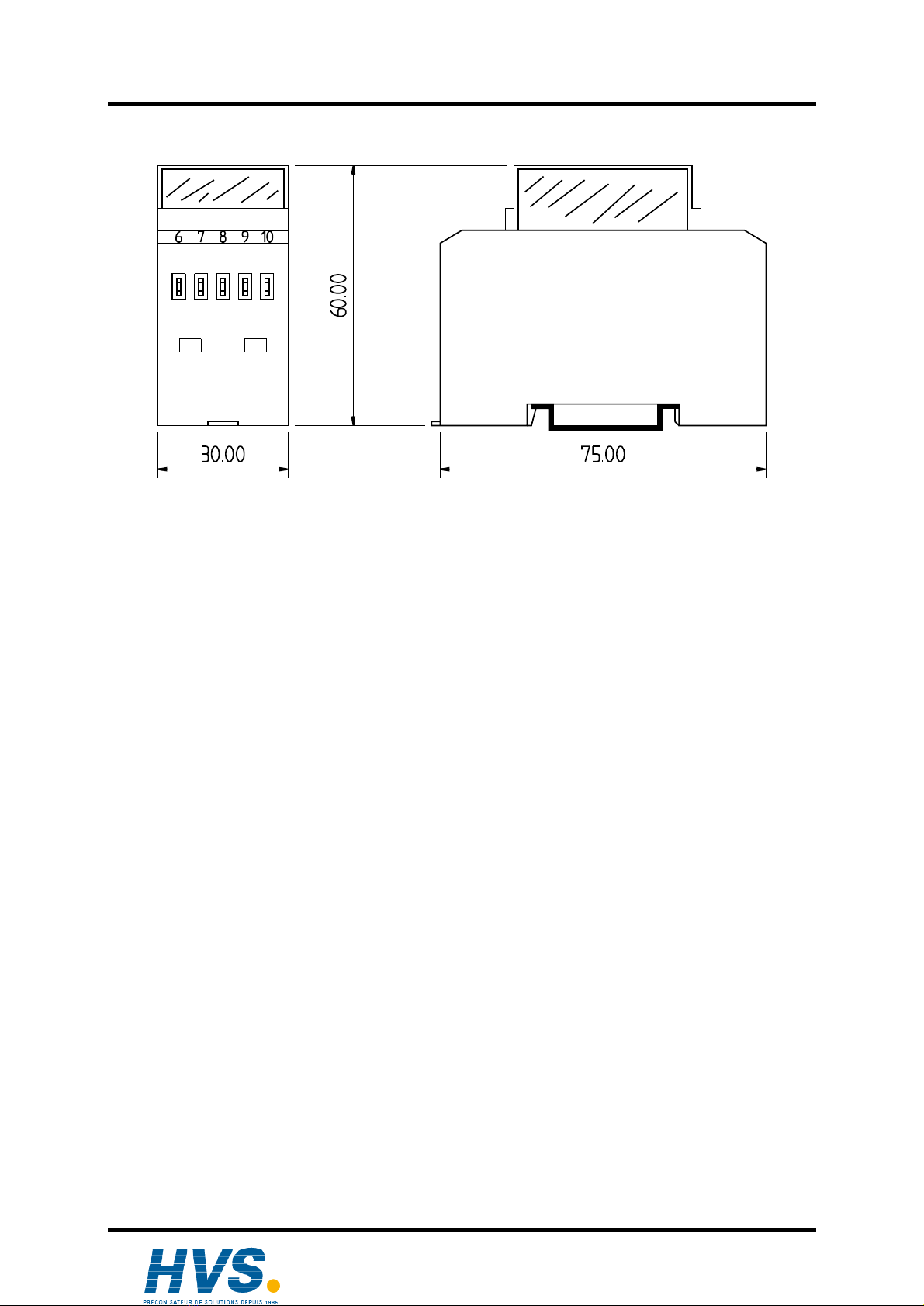
9. Dimensions
10. Technical Data
DisplayAnzeigen.......................................................7LEDforstatus:4xinputs,1xstate ofservice2x
outputs+
Supplyvoltage..........................................................24VDC ±20%, min. 5 Amp.
Current input............................................................max. 8Atop-current in the moment ofswitching
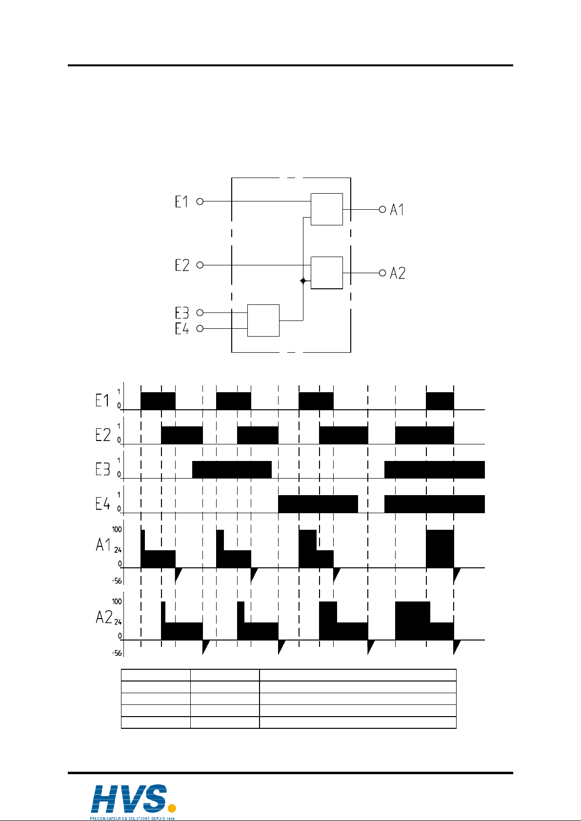
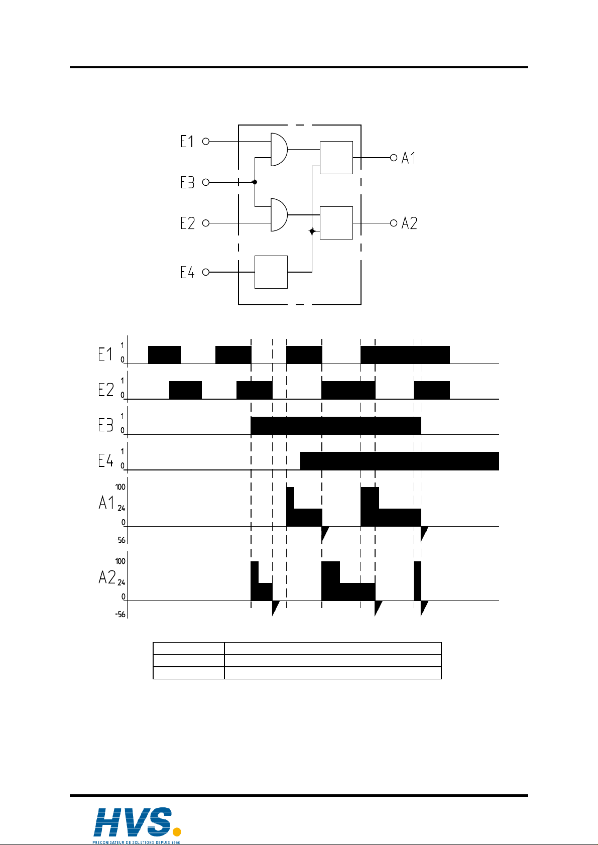
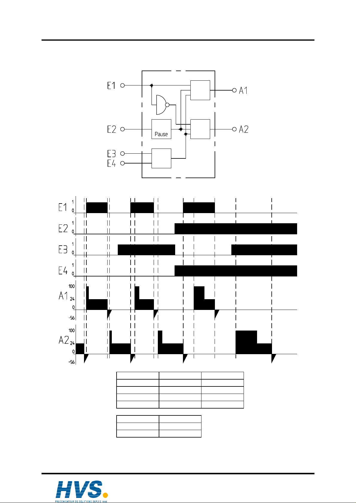
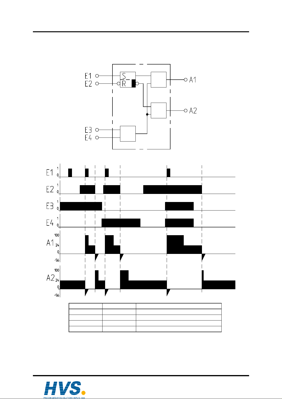
Numberofinputs......................................................4 programable inputs, galvanicallyseparated 4
standard-programs
.................................................................................Example: 2 switching inputs2 inputs
whichdetermine the time-intervalofthe overload-
impulse.
Input voltage.............................................................active 16-30VDC, passive 0-3VDC
Input resistor............................................................2,2kΩ-2,5kΩ
Numberofoutputs ...................................................2
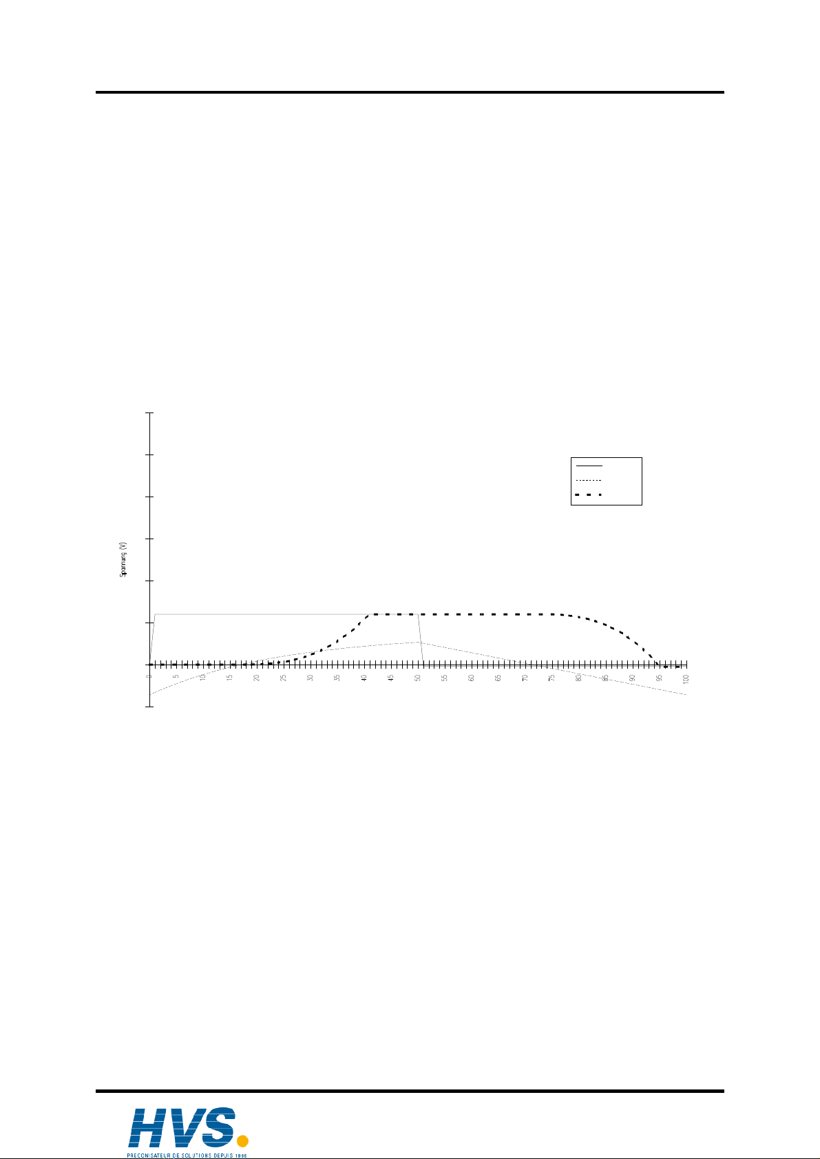
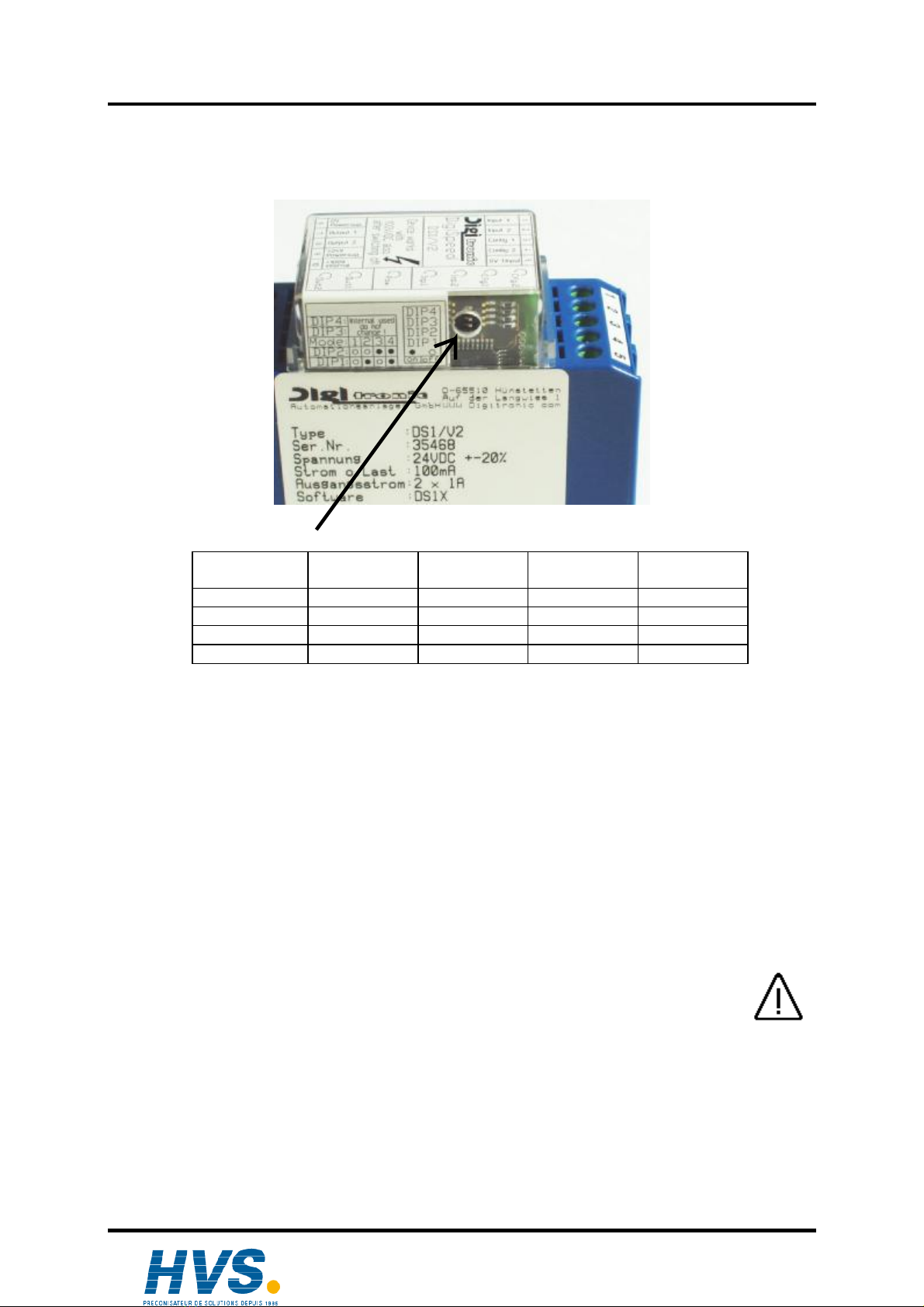
Overload-impulse.....................................................100VDC,
Note: The overload in the device isde-established
during one minute afterswitching off the device.
Duration ofthe overload impulse.............................maybe programed.
Flywheelvoltage.......................................................-56VDC.
Output voltage..........................................................Supplyvoltage -1Vat 1Apermanent current.
(bei24VDC min. 23VDC)
Output current..........................................................1Apermanent current peroutput ,resistant against
short circuits
Delaytimes ..............................................................max. 100µs
Recoverytimes ........................................................see chapterrecoverytimes
Cover........................................................................hardlyignitableThermoplastplastic,continous
temperature up to 100°C
Conductorallocation................................................fivesolidscrewclampsup to 2,5mm²inthe
structuralmodule of5,08mm; with labeling
Assembly..................................................................comfortablesnap-on assemblyonto symmetrical
carriererrail according to EN50 022, rowassembly
possible.
Disembly..................................................................bypulling backthe snap clip.
Dimensions..............................................................see chapter"9. Dimensions"
Covertype................................................................Covercorrespondswith IP20.
Operating temperature.............................................0°to +55°C.
Weight about 110g.
9. DimensionsCovertype.........................................Covercorrespondswith IP20.
Operating temperature.............................................0°to +55°C.
Weight......................................................................about 110g.
Ausgabe: August 04 Seite: 14
2 rue René Laennec 51500 Taissy France
Fax: 03 26 85 19 08, Tel : 03 26 82 49 29
Site web : www.hvssystem.com