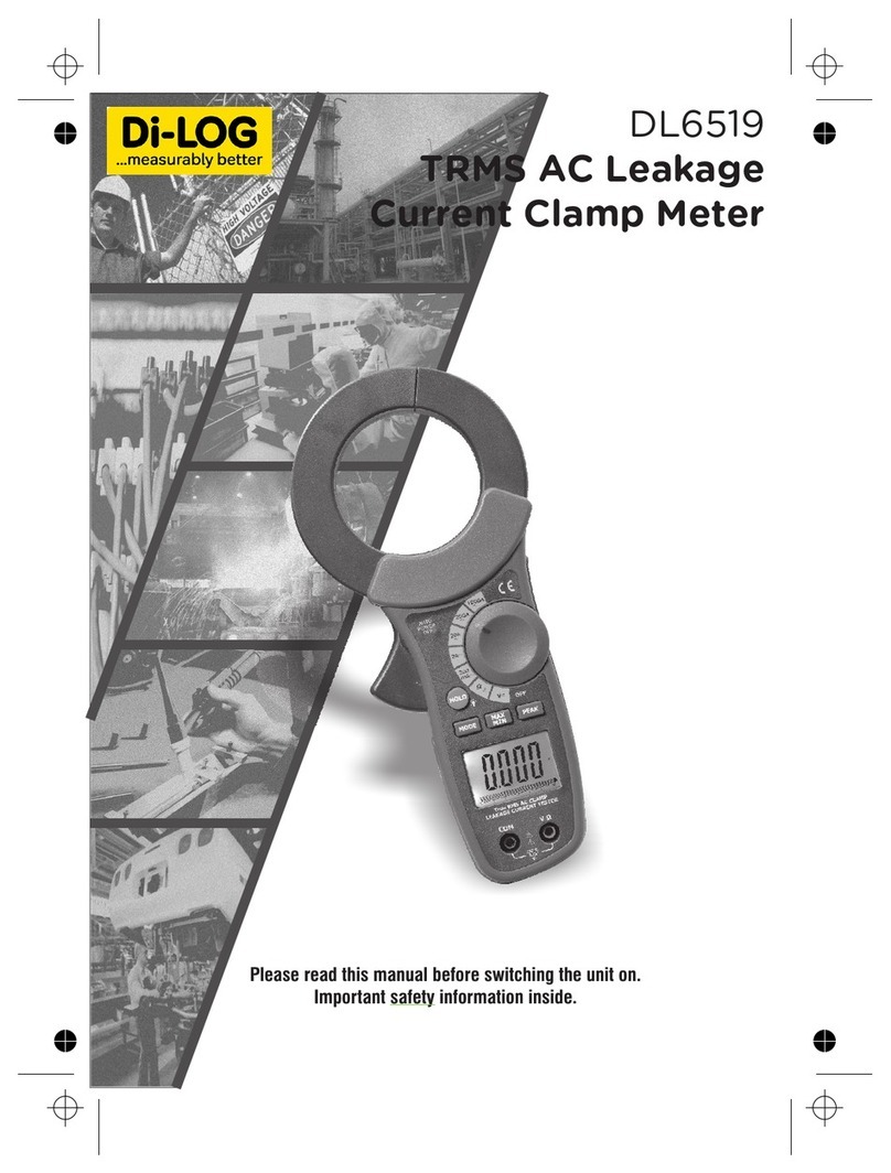
Dilog DL6505 User manual

Warranty & Maintenance
DL6505 200A AC MINI
CLAMP-ON METER
operating manual
Di-Log Test Equipment
28 Wheel Forge Way,
Trafford Park,
Manchester
M17 1EH, UK
tel: + 44 161 87 7 0322 fax: + 44 161 877 1614
email: sales@dilog.co.uk website: www.dilog.co.uk
EN
61010-1
CAT II
600V

This manual contains information that must be
followed for operating the meter safely and
maintaining the meter in a safe operating condition.
If this meter is not used in the manner specied,
the protection provided may be impaired.
Warning! Warns of potential danger, refer
to the instruction manual to avoid personal
injury or damage to the meter.
Caution! Dangerous voltage. Danger of
electrical shock
Continuous double or reinforced insulation
complies with IEC536, class 11
Symbol of conformity, conrms conformity with
relevant EU directives. The meter complies with
EMC directives (89/336/EEC). Specically stand-
ards EN 50081-1 and EN 50082-1 as well as the
Low Voltage Directive (73/23/EEC) described in
the standard EN 61010-1.
The meter has been designed in accordance with
the safety regulations for electronic measuring
instruments, EN 61010-1, IEC 61010
Voltages above 75V DC or 50V AC may constitute a
serious shock hazard.
Before using the meter casing check for physical
damage to the casing in particular around the
connectors. If the case is damaged do not use
the meter.
Safety Information

Safety Information Safety Information
Check the test leads for damaged insulation or
expose metal. Check the leads for continuity. Replace
damaged leads with identical model or specication
before using the meter.
Where applicable use GS38 approved leads (not
supplied) these are available from Di-Log. When using
test leads keep ngers behind the nger guards.
Do not apply more than the rated voltage, as marked
on the meter between the terminals or between any
terminal and ground.
Before making a measurement ensure that the rotary
switch is set to the appropriate range. Do not turn the
rotary switch whilst making a measurement.
Use the appropriate terminals, function and range for
your measurements. If the value to be measured is
not known use the maximum measurement position
and reduce the range step by step until a satisfactory
reading is obtained.
Do not use or store the meter in an environment
of high temperature, humidity, fumes, vapour,
gaseous, inammable and strong magnetic eld.
The performance and safety of the use may be
compromised in such circumstances.
Disconnect circuit power and discharge all high
voltage capacitors before testing resistance,
continuity, diodes, capacitance or current.

Safety Information
Before measuring current check the meters fuses
and turn off power to the circuit before connecting
the meter to the circuit.
Replace the battery as soon as the low battery
indicator appears. If the battery is low the meter
may give false readings.
Turn the meter power off when not in use,. Remove
the battery if the meter is in use for a long period.
Constantly check the battery as it may have leaked.
A leaking battery will damage the meter.
The meter may only be opened by a qualied service
technician for calibration and repair.

Safety Information Features
• 3-1/2 digit (2000 count) LCD display
• High resolution to 10mA AC
• Built-in non-contact AC voltage
detector plus ashlight
• MAX Hold and Data Hold
• Auto power off
• (18mm) Jaw opening

Specications
Display:
3-1/2 (2000 count) Digit LCD
Polarity: Minus sign ( - ) indicates negative polarity
Overload indication: “OL” displayed on the LCD
DCA zero adjust: One touch zero key
Display rate: 2 readings/second, nominal
Battery: Two 1.5V AAA batteries
Low Battery indication: “BATT” displayed on the LCD
Auto OFF: approx. 7 minutes
Operating conditions:
32˚F to 86˚F (0˚C to 30˚C) 90%RH; 86˚F to 104˚F (30˚C
to 40˚C) 75%RH; 104˚F to 122˚F (40˚C to 50˚C) 45%RH
Storage conditions: - 14˚F to 140˚F (-30˚C to 60˚C); <
90% Relative Humidity
Altitude: Operate at less than 3000 meters
Weight: 175g including battery
Dimensions: 164 x 65 x 32mm
Jaw opening: 18mm
Standards: IEC 1010, Category II 600V

Specications Specications
6
2
4
1
5
7
Range Specications
Function Range Resolution Accuracy (of reading)
AC Current (50/60Hz) 2A 1mA
80A 200mA ±(3.0% + 8 digits)
Non-Contact AC Voltage 100VAC to 600VAC 50/60Hz
3
9
8

Specications
Meter Description
1. Current sensor jaw
2. Torch button
3. Rotary function switch
4. Data HOLD key
5. LCD display
6. Clamp trigger
7. MAX HOLD key
8. Non-contact AC voltage indicator light
9. Non-contact AC voltage detector probe tip
Function Maximum Inputs
AC Current 200A
Input Limits

Specications AC Current Measurements
Input Limits
1. Set the Function switch to the ACA range.
2. Press the jaw trigger and clamp around, fully
enclosing a single conductor. Do not allow a gap
between the two halves of the jaw. Refer to the
diagram at right for the correct way to enclose a
single conductor.
3. Read the ACA value on the LCD.
wrong correct

Non-Contact AC
Voltage Meassurements
Warning:
RISK OF ELETROCUTION. BEFORE USE, ALWAYS TEST
THE VOLTAGE DETECTOR ON A KNOWN LIVE CIRCUIT
TO VERIFY PROPER OPERARTION.
1. Touch the probe tip to the hot conductor or
insert into the hot side of the electrical outlet.
2. If AC voltage is present, the detector light will
illuminate.
Note:
The conductors in electrical cord sets are often
twisted. For best results, rub the probe tip along a
length of the cord to assure placing the tip in close
proximity to the live conductor.
Note:
The detector is designed with high sensitivity. Static
electricity or other sources of energy may randomly
trip the sensor. This is normal operation.

Non-Contact AC
Voltage Meassurements
Torch
Press and hold the top button to turn the torch on.
Release the button to turn the torch off.
Data Hold
To freeze the current reading on the LCD, press the
“Hold Backlight” key. The word HOLD will appear on the
LCD while the meter is in the Data Hold mode. To release
the Data Hold function and return the meter to normal
operation, press the “Hold Backlight” key again. The
word HOLD will switch off.
MAX Hold
To hold the highest reading on the LCD, press the MAX
hold button. The MAX hold button is located on the left
side of the meter (bottom button). The meter reading will
not change as readings change, rather it will only display
the highest reading encountered since the MAX hold
button was pressed. Press the MAX hold button again to
return to normal operation.
Auto Power Off
The auto off feature will turn the meter off after 7 minutes.
Battery Replacement
1. When the low battery symbol appears on the
LCD the batteries must be replaced.
2. Power down and remove the rear battery
compartment Phillips screw.
3. Lift off the battery compartment cover and replace
the two 1.5V AAA cells.
4. Replace compartment cover and secure the screw..
Operations

Warranty & Maintenance
Di-Log Test Equipment
28 Wheel Forge Way,
Trafford Park,
Manchester
M17 1EH, UK
tel: + 44 161 87 7 0322 fax: + 44 161 877 1614
email: [email protected].uk website: www.dilog.co.uk
24 Month Warranty
Di-Log instruments are subject to stringent quality controls.
If in the course of normal daily use a fault occurs we will
provide a 24 month warranty (only valid with invoice).
Faults in manufacture and materials defect will be rectied
by us free of charge, provided the instrument has not been
tampered with and returned to us unopened.
Damage due to dropping abuse or misuse is not covered
by the warranty.
Outside the warranty period we offer a full repair and
re-calibration service.
Maintenance
WARNING Do not attempt to repair or service your meter
unless you are qualied to do so and have the relevant
calibration, performance test and service information.
To avoid electrical shock or damage to the meter do not
get water inside the case.
Periodically wipe the case with a damp cloth and mild
detergent. Do not use chemical solvent.
Clean the input terminals with cotton bud, as dirt or moisture
in the terminals can affect readings.
EN
61010-1
CAT II
600V
Table of contents
Other Dilog Measuring Instrument manuals
Dilog
Dilog PL107N User manual

Dilog
Dilog DL6507 User manual
Dilog
Dilog DL6780 Combi Volt 1 User manual
Dilog
Dilog DL6702 User manual
Dilog
Dilog DL7206 User manual
Dilog
Dilog DL7040 User manual

Dilog
Dilog DL7030 User manual
Dilog
Dilog DL6799 User manual
Dilog
Dilog CombiVolt DL6780 User manual
Dilog
Dilog DL6506 User manual
