OPTOKON PM-800-GL User manual

is registered trademark of OPTOKON, a.s. Other names and trademarks mentioned herein may be the
trademarks of their respective owners.
OPTOKON, a.s., Cerveny Kriz 250, 586 01 Jihlava, Czech Republic
tel. +420 564 040 111, fax +420 564 040 134, WWW.OPTOKON.COM, INFO@OPTOKON.CZ
s/w: 1.2 23/05/2017
PM-800-GL
Optical Power Meter
INSTRUCTION MANUAL

2
is the registered trademark of OPTOKON, a.s. Other names and trademarks mentioned
herein may be the trademarks of their respective owners
All rights reserved. No parts of this work may be reproduced in any form or by any means - graphic, electronic,
or mechanical, including photocopying, recording, taping or information storage and retrieval systems - without
the written permission of the publisher.
Products that are referred to in this document may be either trademarks and/or registered trademarks of the
respective owners. The publisher and the author make no claim to these trademarks.
While every precaution has been taken in the preparation of this document, the publisher and the author
assume no responsibility for errors or omissions, or for damages resulting from the use of information
contained in this document or from the use of programs and source code that may accompany it. In no event
shall the publisher and the author be liable for any loss of profit or any other commercial damage caused or
alleged to have been caused directly or indirectly by this document.
OPTOKON, a.s.
Cerveny Kriz 250
586 01 Jihlava
Czech Republic
tel. +420 564 040 111
fax +420 564 040 134
WWW.OPTOKON.COM

PM-800-GL INSTRUCTION MANUAL
3
Contents
1Introduction.................................................................................................4
2Features ......................................................................................................4
3Application...................................................................................................4
4Accessories ..................................................................................................5
4.1 Standard......................................................................................................................5
4.2 Optional......................................................................................................................5
5Specifications ...............................................................................................6
6Safety information ........................................................................................7
7Maintenance .............................................................................................. 10
7.1 Battery care ..............................................................................................................10
7.2 Instrument care.........................................................................................................10
7.3 Recommended cleaning and mating instructions.....................................................11
8Instrument and button function description .................................................. 12
8.1 Menu #1 – Absolute power measurement mode......................................................13
8.2 Menu #2 – Relative power measurement mode.......................................................14
8.3 Menu #3 – Working with the internal memory........................................................15
8.3.1 SAVE RESULT ...............................................................................................16
8.3.2 BROWSE RESULTS.......................................................................................17
8.3.3 UPLOAD MEMORY.......................................................................................17
8.3.4 ERASE MEMORY..........................................................................................18
8.3.5 HOME..............................................................................................................18
9Measurement loss....................................................................................... 19
9.1 Basic theory..............................................................................................................19
9.2 Method 6 ..................................................................................................................20
9.2.1 Setting the reference.........................................................................................20
9.2.2 Measurement Loss............................................................................................21
9.3 Method 7 ..................................................................................................................22
9.3.1 Setting the reference.........................................................................................22
9.3.2 Measurement Loss............................................................................................23
9.4 High power measurement.........................................................................................24
10 Setting up data transfer........................................................................... 25
11 Power loss and decibels........................................................................... 28
12 Notes ..................................................................................................... 29
13 Calibration, service center........................................................................ 30

PM-800-GL INSTRUCTION MANUAL
4
1Introduction
The PM-800-GL optical power meter is designed to measure absolute or
relative optical power in optical networks. The AWD (Auto Wavelength
Detection) function facilitates the tester settings and eliminates the operator´s
failure. The memory capacity allows storage and uploading of up to 3000
measurements including memory position or fiber number, wavelength, absolute
value or relative value and insertion loss. The SmartProtocol PC evaluation
software supports memory download and test report generation.
The rechargeable Li-Pol battery ensures long term working with a minimum
service life of 5 years. Batteries can be charged via a USB port or external
AC/DC adaptor. The microprocessor controlled charging process ensures optimal
battery status and extended operation time.
The PM-800-GL series can measure a wide range of optical power level, -70 to
+36 dBm.
2Features
Small size, light weight
InGaAs or Si photodetector
Four types according to dynamic range
Detection of modulation 270 Hz, 1 kHz, 2 kHz
AWD (Auto Wavelength Detection) function
Two levels high capacity memory: Cable No., Fiber No.
SmartProtocol PC software - memory download, reporting solution
Firmware upgrade via USB
S/N displayed during switch on
Displayed units: dBm, dB, W
Reading/writing measured data from/to tag (chip)
High dynamic range
Absolute and Relative optical power measurement
Powered by Li-Pol battery charging via USB port
10 min Auto Off, battery status indicator
Easy to use with menu navigation
Simple and fast calibration
3Application
Absolute or relative optical power measurement
Optical network measurements
Measurement output power of optical transmitters
Measurement input power of optical receivers
Measurement attenuation in fiber cabling, in conjunction with the LS-800
Optical light source
Measurement loss in connectors, splices, adaptors, switches and other
components
Easy and rapid identification of failure points in fiber networks
Suitable for SM and MM applications

PM-800-GL INSTRUCTION MANUAL
5
4Accessories
4.1 Standard
Power meter
Changeable input adaptors
USB cable
Li-Pol battery
Power charging adapter 5 V DC
Calibration certificate
Hard carrying case TE-HC-03
Smart Protocol PC software
Data Exporter PC software
4.2 Optional
Master patchcords
Master adaptors
USB Power charging adaptor TE-HC-03
4.3 Input adapters:
TE-AGP-FC
FC adaptor
TE-AGP-SC
SC adaptor
TE-AGP-ST
ST adaptor
TE-AGLP-FC
FC adaptor
TE-AGLP-SC
SC adaptor
TE-AGLP-ST
ST adaptor
TE-AGLP-LC
LC adaptor
Compatible with adapter type G Compatible with adapter type GL

PM-800-GL INSTRUCTION MANUAL
6
5Specifications
GeneralspecificationsValue Unit Note
Dimensions165x80x40 mm withTE‐AGP‐250 adapter
Weight340 gwithbattery
Operationtemperature‐10to+60/0to+45°CDischarging/charging
battery
Storagetemperature‐10 to+45
°
C
Humidity(non‐
condensing)0to95%
PowerMeterPM‐800‐
06
PM‐800‐
16
PM‐800‐
26
PM‐800‐
36
Dynamicrange‐70to+6‐60to+16‐50to+26‐40 to
+36dBm
DetectorInGaAsSi
Wavelengthrange850to1700 400to1100 nm
Workingwavelengths850,1300,1310,1490,
1550,1625650,850,980 nmcanbecustomized
Accuracy±5 % 1310,1550nmat‐20 dBm
Resolution0.25 dB at25°C
Tonedetection0.270,1,2kHz
Autoswitching(AWD)Yes ‐
AWD/Modulation
Detection‐50/‐45dBm1300–1625nm/850nm
DatastorageUpto3000 ‐numberofmeasurements
DisplayunitsdBm,dB,W‐
6Ordering code:
PM-800 - XX - XX - (SI)
Dynamic range Adaptor type Photodetector
06 -70 to +6 dBm G 2.51, FC, SC, ST - InGaAs
16 -60 to +16 dBm GL LC, FC, SC, ST SI Si
26 -50 to +26 dBm
36 -40 to +36 dBm
Note: 1) G-type without additional adapter is suitable for ferrule 2.5 mm
PM-800 with adapter type G PM-800 with adapter type GL

PM-800-GL INSTRUCTION MANUAL
7
7Safety information
The PM-800 instrument emits no optical power itself and does not create any
hazards to the user. To ensure a high level of operator safety during installation,
commissioning and operating the equipment, as well as ensuring that the equipment
remains undamaged, it is necessary to consider the following general warnings and
recommendations.
For high power optical signal the safety rules for laser systems must be observed,
see laser classification.
Installation, commissioning, operation and service of equipments with high power
level are only allowed to be carried out by an authorised person.
Use only the equivalent connector types to those built into the instrument in
order to avoid damage to the instrument components.
Optical connectors must be clean, in case the connectors are not perfectly clean –
please clean them according to the procedure described in the technical
specification for the relevant connectors.
Never use magnifying devices to inspect optical fiber ends unless you are sure
that no optical power is being emitted.
Use only magnifying devices with a built-in infra-red filter to ensure safety.
During operation, testing or maintenance of a fiber optic system, never look into
an active fiber optic cable. Infrared radiation may be present and permanent eye
damage can result.
Avoid direct exposure to the beam.
Do not activate the laser when there is no fiber attached to the optical output
connector.
Under no circumstances should you look into the end of an optical cable attached to
the optical output when the device is operational. The laser radiation can seriously
damage your eyesight.
7.1 Laser classification
A laser is a light source that can be dangerous to the people exposed to it. Even low power
lasers can be hazardous to eyesight. A person exposed to laser radiation (especially
invisible radiation) may be unaware that damage is occurring. Some lasers are so powerful
that even the diffuse reflection from a surface can be hazardous to the eye. Laser radiation
predominantly causes eye injury via thermal effects on the retina. A transient increase of
only 10 °C can destroy retinal photoreceptors
Lasers have been classified by wavelength and maximum output power into four classes
and a few subclasses since the early 1970s. The classifications categorize lasers according
to their ability to produce damage in exposed people, from class 1 (no hazard during
normal use) to class 4 (severe hazard for eyes and skin). There are two classification
systems, the "old system" used before 2002, and the "revised system" being phased in
since 2002. The latter reflects the greater knowledge of lasers that has been accumulated
since the original classification system was devised, and permits certain types of lasers to
be recognized as having a lower hazard than was implied by their placement in the original

PM-800-GL INSTRUCTION MANUAL
8
classification system. The revised system is part of the revised IEC 60825 standard. From
2007, the revised system is also incorporated into the US-oriented ANSI Laser Safety
Standard (ANSI Z136.1). Since 2007, labeling according to the revised system is accepted
by the FDA on laser products imported into the US. The old and revised systems can be
distinguished by the 1M, 2M and 3R classes used only in the revised system and the 2A
and 3A classes used only in the old system. Class numbers were designated using Roman
numerals (I–IV) in the US under the old system and Arabic numerals (1–4) in the EU. The
revised system uses Arabic numerals (1–4) in all jurisdictions.
The classification of a laser is based on the concept of accessible emission limits (AEL) that
are defined for each laser class. This is usually a maximum power (in W) or energy (in J)
that can be emitted in a specified wavelength range and exposure time. For infrared
wavelengths above 4 μm, it is specified as a maximum power density (in W/m2). It is the
responsibility of the manufacturer to provide the correct classification of a laser, and to
equip the laser with appropriate warning labels and safety measures as prescribed by the
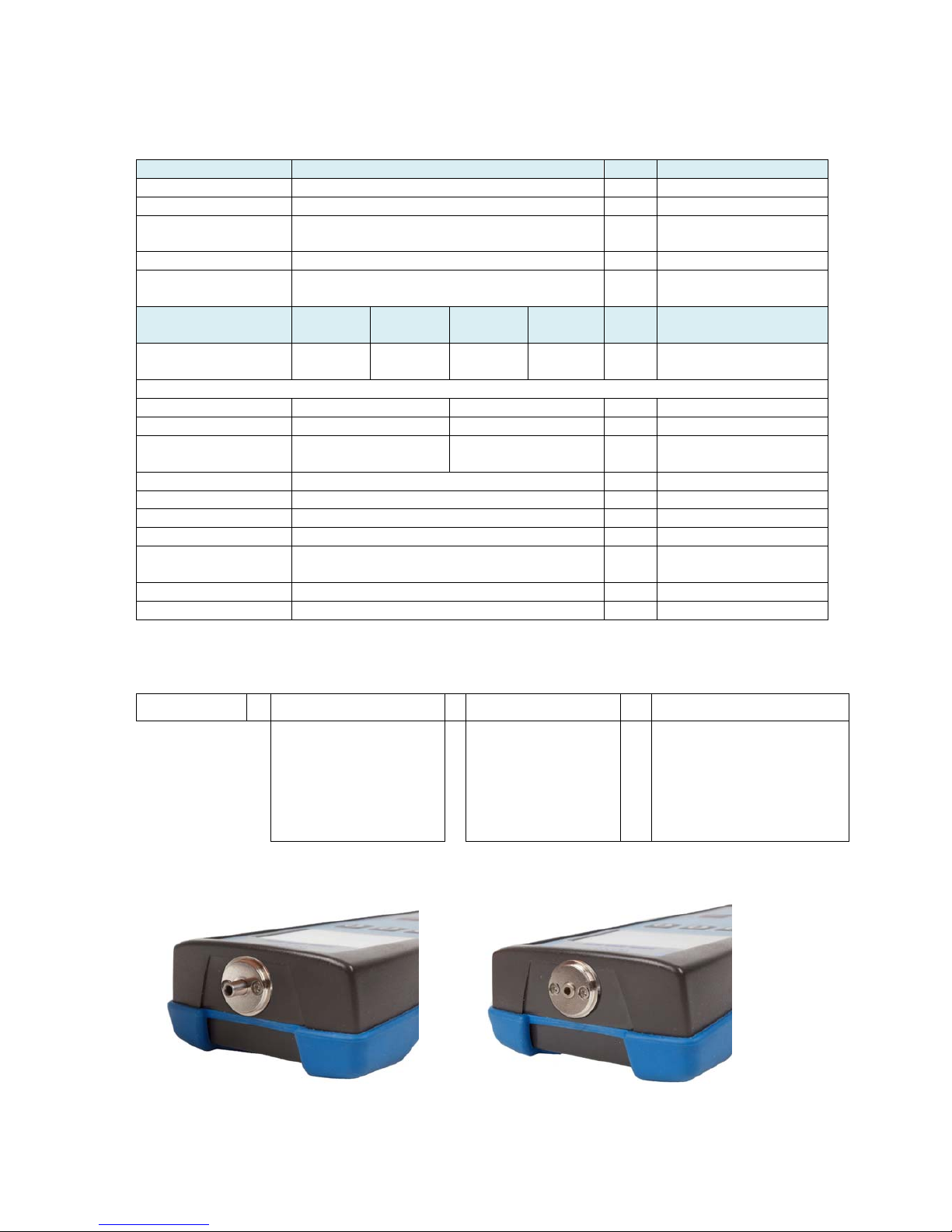
regulations. Safety measures used with the more powerful lasers include key-controlled
operation, warning lights to indicate laser light emission, a beam stop or attenuator, and
an electrical contact that the user can connect to an emergency stop or interlock
Below, the main characteristics and requirements for the classification system from 2002
are listed, along with typical required warning labels. Additionally, classes 2 and higher
must have the triangular warning label shown here and other labels are required in specific
cases indicating laser emission, laser apertures, skin hazards, and invisible wavelengths
Class 1
A class 1 laser is safe under all conditions of normal use. This means the maximum
permissible exposure (MPE) cannot be exceeded. This class includes high-power lasers
within an enclosure that prevents exposure to the radiation and that cannot be opened
without shutting down the laser. For example, a continuous laser at 600 nm can emit up to
0.39 mW, but for shorter wavelengths, the maximum emission is lower because of the
potential of those wavelengths to generate photochemical damage. The maximum
emission is also related to the pulse duration in the case of pulsed lasers and the degree of
spatial coherence.
Class 1M
A Class 1M laser is safe for all conditions of use except when passed through magnifying
optics such as microscopes and telescopes. Class 1M lasers produce large-diameter beams,
or beams that are divergent. The MPE for a Class 1M laser cannot normally be exceeded
unless focusing or imaging optics are used to narrow the beam. If the beam is refocused,
the hazard of Class 1M lasers may be increased and the product class may be changed. A
laser can be classified as Class 1M if the total output power is below class 3B but the
power that can pass through the pupil of the eye is within Class 1.
Class 2
A Class 2 laser is safe because the blink reflex will limit the exposure to no more than 0.25
seconds. It only applies to visible-light lasers (400–700 nm). Class-2 lasers are limited to 1
mW continuous wave, or more if the emission time is less than 0.25 seconds or if the light
is not spatially coherent. Intentional suppression of the blink reflex could lead to eye injury.
Many laser pointers are class 2.

PM-800-GL INSTRUCTION MANUAL
9
Class 2M
A Class 2M laser is safe because of the blink reflex if not viewed through optical
instruments. As with class 1M, this applies to laser beams with a large diameter or large
divergence, for which the amount of light passing through the pupil cannot exceed the
limits for class 2.
Class 3R
A Class 3R laser is considered safe if handled carefully, with restricted beam viewing. With
a class 3R laser, the MPE can be exceeded, but with a low risk of injury. Visible continuous
lasers in Class 3R are limited to 5 mW. For other wavelengths and for pulsed lasers, other
limits apply.
Class 3B
A Class 3B laser is hazardous if the eye is exposed directly, but diffuse reflections such as
from paper or other matte surfaces are not harmful. Continuous lasers in the wavelength
range from 315 nm to far infrared are limited to 0.5 W. For pulsed lasers between 400 and
700 nm, the limit is 30 mJ. Other limits apply to other wavelengths and to ultrashort
pulsed lasers. Protective eyewear is typically required where direct viewing of a class 3B
laser beam may occur. Class-3B lasers must be equipped with a key switch and a safety
interlock.
Class 4
Class 4 lasers include all lasers with beam power greater than class 3B. In addition to
posing significant eye hazards, with potentially devastating and permanent eye damage as
a result of direct beam viewing, diffuse reflections are also harmful to the eyes within the
distance called the Nominal Hazard Zone. Class 4 lasers are also able to cut or burn skin.
In addition, these lasers may ignite combustible materials, and thus represent a fire risk, in
some cases. Class 4 lasers must be equipped with a key switch and a safety interlock.

PM-800-GL INSTRUCTION MANUAL
10
8Maintenance
8.1 Battery care
The PM-800 comes equipped with a built-in charger and is powered by Li-Pol battery.
Charging – via USB port (PC) or by using external USB power charging
adaptor (standard accessories)
Before using the PM-800 for first time, charge fully the battery.
Use only supplied USB power charging adapter.
Charge the batteries not to fully charge status before storing PM-800 for a
long period.
If you are not going to use the PM-800 for long period, the batteries will lose
its charge during storage. Charge the batteries once every six months.
The batteries are a consumable. Repeated charging and discharging decreases
batteries lifetime.
8.2 Instrument care
During storage and transport keep the instrument in its carry case to protect
against crushing, vibration, dust and moisture.
Where possible keep the instrument away from strong sunlight.
Clean the instrument housing using alcohol or other cleaning agents. Acetone or
other active solvents may damage the case.
The instrument is resistant to normal dust and moisture, however it is not
waterproof. If moisture does get into instrument, dry it out carefully before
using it again.
-48.95 dBm
LOSS MEM
1310nm
19 nW
-48.95 dBm
LOSS MEM
1310nm
19 nW
battery status
indicator
charging

PM-800-GL INSTRUCTION MANUAL
11
8.3 Recommended cleaning and mating instructions
Cleanliness will affect the performance of an
optical fiber system. Perform the following
procedures prior the installation. Clean all
connectors, adapters, and attenuators before
making any connections. The following cleaning
materials are recommended and may form part
of Your cleaning kit:
Lint-free laboratory wipes.
Isopropyl alcohol in pressurised
dispenser
Lint free pipe cleaners.
Clean, dry, oil-free compressed air.
CLEANING
Connectors/Terminators:
1. Fold a clean, new wipe into a 2” by 2” square
pad.
2. Moisten, but do not saturate, the pad with
alcohol making a spot approximately 1/2” in
diameter.
3. Open the protective cap (E2000 only).
4. Press the ferrule and face into a wet spot on
the wipe. Using force, twist the ferrule so
that a hard wiping action takes place. Repeat
twice, using a clean alcohol-moistened at
each time.
5. Press the ferrule end face into a dry spot on
the wipe. Using force, twist the ferrule so
that a hard wiping action takes place
6. Close the cap (E2000 only)
7. Discard the used pad.
Attenuators:
1. For an exposed ferrule (in-line type), see
connector cleaning procedure, blow the other
end dry with clean compressed air.
2. Clean bulkhead attenuators only by blowing
with clean compressed air.
Adapters:
1. Moisten one end of a lint-free pipe cleaner
with alcohol.
2. Remove express alcohol from the pipe
cleaner with a clean wipe.
3. Insert the moisten pipe cleaner into either
end of the adapter and scrub in and out so
that the inside surface of the adapter is
wiped by the pipe cleaner. Repeat this step
for the opposite end.
4. Insert the dry end of the pipe cleaner into
either end of the adapter to remove any
residual alcohol. For oversized adapters
(biconic), slightly blow the middle of the pipe
cleaner fog better surface contact. Repeat
this step for the opposite end.
5. Blow the adapter dry with clean compressed
air.
MATING
SC, MT-RJ, LC:
1. Align the housing key with the slot in the
adapter.
2. Push the connector into the adapter until a
click is heard/felt indicating the latching
system is engaged. When the SC connector
is fully engaged, the white stripes on the side
of the housing should be hidden inside the
adapter.
FC:
1. Insert the ferrule tip into the adapter.
2. Align the key with the slot in the adapter.
3. Push the connector into the adapter until the
coupling nut reaches the adapter housing.
4. Screw the coupling nut clockwise into the
adapter.
E 2000:
1. Align slots with key on adapter.
2. Push the connector into the adapter until it
clicks.
ST:
1. Align the ferrule hub key with the slot in the
adapter.
2. Insert the connector into the adapter until
the coupling nut reaches the adapter
housing.
3. Align the bayonet slots-on the coupling nut
with the pins on the outside of the adapter.
4. Push the coupling nut into the adapter while
rotating the coupler nut clockwise to lock the
bayonet and secure the connection.
Infrared radiation is invisible and can
seriously damage the retina of the eye Do
not look into the ends of any optical fiber.

PM-800-GL INSTRUCTION MANUAL
12
9Instrument and button function description
[ON/OFF]
Press to turn the unit on.
Press to turn the unit off.
After switching on, the type of device, serial number and firmware version will be
displayed.
The unit will start up with “AUTO OFF” feature – symbol “ “ will be diplayed.
For disable the AUTO OFF feature press and hold the ON/OFF key until symbol
“ “ disappear.
If activated, the unit will turn off after approximately 10 minutes of no activity.
[BL]
Turns the Display Backlight On and Off.
[ ]
Meaning of these keys depends on current menu.
PM-800
SW:1.1
S/N: PM8009009
PM-800
SW:1.1
S/N: PM8009009
Power meter port
with 2.5 mm
universal adaptor
USB port
(charging)
Operatin
g
keys
ON/OFF key
LCD display
Calibration label
BL key

PM-800-GL INSTRUCTION MANUAL
13
9.1 Menu #1 – Absolute power measurement mode
In the absolute power measurement mode the absolute value of the optical signal in
dBm units is shown on the display.
This screen will appear after the instrument is switched on and information regarding
the type of device, serial number and firmware version will appear.
Reading the display:
[]
Selects 850, 1300, 1310, 1490, 1550, 1625 nm wavelengths or AWD
(Auto Wavelength Detection).
Auto Wavelength Detection is notified by the “AWD” on the display.
Note: LS800 with AWD modulation ON must be connected to PM-800 in order to use
this feature.
[LOSS]
Activates the relative power measurement mode (unit dB).
Recalls the last set reference for a selected wavelength.
Goes to menu #2.
[MEM]
Goes to Memory menu #3.
Starts working with the internal memory.
-48.95 dBm
LOSS MEM
1310nm
19 nW
-25.93 dBm
LOSS MEM
1310nm AWD
19 nW c
selected
wavelength
measured
optical power level
AWD is switched ON

PM-800-GL INSTRUCTION MANUAL
14
9.2 Menu #2 – Relative power measurement mode
In the relative power measurement mode is on the value of optical insertion loss in
dB units which corresponds to performed reference is shown on the display.
Reading the display:
[O.POW]
Returns unit into absolute power measurement mode (unit dBm).
Goes to menu #1.
[REF]
Sets and stores the new reference for the selected wavelength
Note: The new reference must be confirmed by the following screen:
[MEM]
Goes to Memory menu #3.
Starts working with the internal memory.
8.12 dB
O. POW
REF MEM
1310nm
-9.10dBm
L
O
S
S
025. dB
O. POW
REF MEM
G
A
I
N
1310nm
-9.10dBm
CONFIRM
NO
SET NEW
REFERENCE
selected
wavelength
measured
optical loss/gain
reference
level

PM-800-GL INSTRUCTION MANUAL
15
9.3 Menu #3 – Working with the internal memory
The memory of PM-800 has a structured, two-level organization. The results are
stored in memory positions (FIBER) in folders called Cable (CABLE). See table below:
This screen will appear after pressing [MEM] key from Menu#1 or Menu#2
[UP], [DOWN], [OK]
Use these buttons for selection appropriate submenu.
CABLE001 FIBER001
FIBER002
FIBER003
FIBER004
FIBER005
FIBER006
..................
FIBERXXX
CABLE002 FIBER001
FIBER002
FIBER003
FIBER004
FIBER005
FIBER006
..................
FIBERXXX
CABLEXXX FIBER001
FIBER002
FIBER003
FIBER004
FIBER005
FIBER006
..................
FIBERXXX
....................
UP DOWN OK
SAVE RESULT
BROWSE RESULTS
UPLOAD MEMORY
ERASE MEMORY
HOME

PM-800-GL INSTRUCTION MANUAL
16
9.3.1 SAVE RESULT
1. By using [UP] [DOWN] select “SAVE RESULT” and press [OK].
2. Select the cable (folder) using [- CABLE +], the unit will display the number of
saved results under the selected cable, then press [FIBER].
3. The unit will suggest the FIBER position under the selected CABLE.
Accept the suggested FIBER position and save the result by pressing [SAVE] or
change the memory position using [- FIBER +], than press [SAVE] to save the
result.
NOTE: If the selected memory position is already occupied, the “!” mark will appear
on the display.
By pressing [SAVE], the new result will OVERWRITE the selected FIBER position and
the old result will be discarded.
- CABLE + FIBER
CABLE 001
FIBER 004
STORED : 003
- FIBER + SAVE
CABLE 001
FIBER 004
STORED : 003
- FIBER + SAVE
CABLE 001
FIBER 001
!
STORED : 003

PM-800-GL INSTRUCTION MANUAL
17
9.3.2 BROWSE RESULTS
1. By using [UP] [DOWN] select “BROWSE RESULTS” and press [OK]
2. Select the cable (folder) using [- CABLE +], the unit will display the number of
saved results under the selected cable, then press [FIBER].
3. Use [- FIBER +] to browse through the results.
9.3.3 UPLOAD MEMORY
1. By using [UP] [DOWN] select “UPLOAD MEMORY”.
2. Press [OK]. All memory content will be sent to the USB port. More information is
contained in the chapter “setting up data transfer”.
- CABLE + FIBER
CABLE 001
STORED : 003
- FIBER + HOME
CABLE 001
FIBER 004
1310nm
-5.05dB
-9.10dBm
- FIBER + HOME
CABLE 001
FIBER 005
EMPTY
UPLOADING ..

PM-800-GL INSTRUCTION MANUAL
18
9.3.4 ERASE MEMORY
1. By using [UP] [DOWN] select “ERASE MEMORY” and press [OK].
2. Press [CONFIRM] to erase memory or [NO] for return to main screen.
9.3.5 HOME
1. By using [UP] [DOWN] select “HOME”.
2. Press [OK] for return to main screen.
CONFIRM NO
ERASE MEMORY
CONFIRM NO
ERASE MEMORY

PM-800-GL INSTRUCTION MANUAL
19
10 Measurement loss
10.1 Basic theory
Loss measures the signal degradation in a fiber optic cable. A light source injects an
optical signal of the appropriate wavelength into the fiber and a power meter
measures the received signal at the same wavelength.
There are two different measurement methods:
Method 6
Method 7
according to IEC 874-1 4.4.7.4.
Power measurement is the basis of optical testing and determines the power budget
of the fiber optic link by comparing the power of the transmitter and the sensitivity of
the receiver. This difference is the maximum acceptable loss. Power loss is caused by
different phenomena such as attenuation of the fiber, dirty connector mating faces,
connector misalignment, loss of splices and other issues such as sharp fiber bends.
The "end to end" loss test is the most commonly used acceptance test of power loss
in fiber optic links. The test is based on measurement the power difference at the
input and output of the link.
The PM-800 and LS-800 are used for this test, where the light source (LS-800) acts
as a transmitter and the optical power meter (PM-800) as a receiver.
The "end to end" test has two steps:
1. Setting the reference
2. Measurement the loss
Important
All connectors and fiber end faces should be cleaned prior to testing (see
chapter 7.3).
The master cord used to set the reference should be the same type as the
patchcords (cables) to be tested (MM:50/125, 62.5/125 or SM).
It is very important that the connections are not disturbed after the reference
value is established.

PM-800-GL INSTRUCTION MANUAL
20
10.2 Method 6
For method 6 two master cords are used to set the reference. Method 6 cancels the
effects of the master cords and one adaptor for all subsequent measurements.
10.2.1 Setting the reference
1. Connect the first master cord to the power meter (PM-800).
2. Connect the second master cord to light source (LS-800).
3. Use the master adaptor to connect the two fiber ends (pic.1).
4. Power on the light source and by pushing [] select the appropriate wavelength.
5. Power on the power meter and by pushing [] select the appropriate wavelength
range.
6. On the power meter activate the relative power measurement mode - by pushing
[LOSS].
7. Set and store the new reference for the selected wavelength - by pushing [REF]
and than [CONFIRM].
(pic.1)
master patchcord
master adaptor
master patchcord
PM-800 LS-800
Do not disconnect
after referencing
Do not disconnect
after referencing
Table of contents
Other OPTOKON Measuring Instrument manuals
Popular Measuring Instrument manuals by other brands

Rohde & Schwarz
Rohde & Schwarz UPD Application note

Triplett
Triplett 614395003647 user manual

TC Electronic
TC Electronic Clarity M quick start guide

Forbes Marshall
Forbes Marshall CODEL TunnelTech 500 Series Operating and maintenance manual

Atracsys
Atracsys fusionTrack 500 user manual

Winland
Winland EnviroAlert EA200 quick start guide