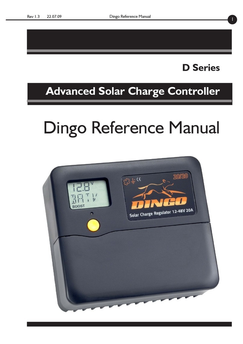
DINGO 4040P User manual

Rev 1.39 03.10.17 Firmware Version 143 ff. Dingo 4040P Reference Manual 1
D4040P
Dingo 4040P Reference Manual
Advanced Solar Charge Controller

Firmware Version 143 ff. Rev 1.39 03.10.17
Dingo 4040P Reference Manual
2
Contents
Introduction .......................................................................................... 4
Additional Installation Notes ........................................................................... 4
Features ........................................................................................................... 5
Overload Protection........................................................................................ 5
Thermal Protection ......................................................................................... 5
Menus .............................................................................................................. 5
1.0 BATV Menu .................................................................................... 6
The Regulation Cycle ..................................................................................... 6
1.1 BOST (Boost) ........................................................................................... 6
Returning to Boost state .......................................................................... 6
1.2 Equalise (optional) .................................................................................... 7
1.3 ABSB (Absorption) ................................................................................... 7
1.4 FLOT (Float) ............................................................................................. 7
2.0 CHRG Menu .................................................................................... 8
CHRG ............................................................................................................. 8
CINT .............................................................................................................. 8
CEXT ............................................................................................................. 8
Generator Control ......................................................................................... 8
GSET ........................................................................................................ 9
GMOD ..................................................................................................... 9
GEXD (Generator Exercise) ..................................................................... 9
GDEL (Generator changeover delay) .................................................... 10
Generator Example ................................................................................ 10
3.0 LOAD Menu ................................................................................. 12
LOAD ........................................................................................................... 12
LINT ............................................................................................................. 12
LEXT ............................................................................................................ 12
Low Battery Disconnect (LSET, LOFF, LON, LDEL) ..................................... 12
4.0 IN Menu ........................................................................................ 13
IN ................................................................................................................. 13
IN/INT .......................................................................................................... 13
IN/EXT ......................................................................................................... 13
5.0 OUT Menu .................................................................................... 13
OUT .............................................................................................................. 13
OUT/INT ..................................................................................................... 13
OUT/EXT .................................................................................................... 13
6.0 DATA Menu (Retrieving Performance Data) .............................. 14
6.1 & 6.2 VMAX & VMIN ............................................................................. 14

Rev 1.39 03.10.17 Firmware Version 143 ff. Dingo 4040P Reference Manual 3
6.3 FTIM (Float time Display) ....................................................................... 14
6.4 SOC (State of Charge Display) ............................................................... 14
6.5 TEMP (External Battery Temperature Sensor Display) .......................... 15
Setting Lockout .................................................................................. 15
6.6 SOLV (Solar Voltage Display) ................................................................. 15
6.7 HIST (History display) ............................................................................ 15
7.0 SET menu ..................................................................................... 17
7.1 TIME ....................................................................................................... 17
7.2 VOLT ...................................................................................................... 17
7.3 PROG (Adjusting Regulation Settings) .................................................... 17
Program Function Table (Generic Programs) ......................................... 17
Program Description .............................................................................. 17
Settings Used in Programs 0-3 ............................................................... 18
Settings for Program 4 ........................................................................... 18
7.4 REG menu (Customising Regulation Settings) ........................................ 19
7.4.1 HYST (Hysteresis Value) ................................................................ 19
7.4.2 Charge Current Limit ................................................................... 20
7.4.3 TCMP (Temperature compensation) ............................................ 20
Connecting a Temperature Sensor .................................................. 21
7.5 MODE Menu (Adjusting Configuration Settings) ................................... 22
7.5.1 LSET & GSET Controlling the load and G outputs ........................ 22
7.5.2 ESET Controlling external switches ............................................... 24
7.5.3 BSET: Configuring B- Sense Input .................................................. 24
7.5.4 BAT2 - Second battery control ..................................................... 26
7.5.5 PWM and Slow Switching .............................................................. 27
7.5.6 BCAP Setting battery capacity ...................................................... 28
7.5.7 ALRM Setting an alarm point ........................................................ 28
7.5.8 RSET & DFLT Reseting and setting factory defaults ...................... 28
7.6 EVNT Menu (Using the Event Controller) ............................................. 29
Examples: ............................................................................................... 32
8.0 Setting up a larger system .......................................................... 33
A.0 Appendices .................................................................................. 35
A.1 Accessories ............................................................................................ 35
A.2 The Alarm Led ....................................................................................... 36
A.3 Current limits & thermal derating .......................................................... 36
A.4 Block Diagram ....................................................................................... 36
A.5 Mechanical Information .......................................................................... 38
Programs 0-3 Menu System & Legal statement on warranty ........................ 39
Program 4 Menu System (for custom settings) ............................................. 40
A.6 History record sheets ............................................................................. 42
A.7 Specifications .......................................................................................... 33

Firmware Version 143 ff. Rev 1.39 03.10.17
Dingo 4040P Reference Manual
4
Introduction
Please read the User Guide before reading this
manual.
In most cases, the User Guide provides all the
information needed for effective installation of
the Dingo, (D4040P) and there is no need for the
user to read this Reference Manual.
Some users will require further information. This
manual provides a detailed technical description
of the operation of the controller. This manual
assumes more technical knowledge than the User
Guide.
If you are in any doubt, it is recommended you do not
adjust the advanced settings described in this manual.
Incorrect adjustment may reduce the effectiveness of
your Dingo and could damage your battery.
All voltage values used in this manual assume
a 12V system. Scale voltages for other system
voltages (e.g. 24V system = voltages x 2, 48V
system = voltages x 4)
Additional Installation Notes
Ensure that you have followed the installation
instructions on pages 3-7 of the User Guide. The
Dingo can be used for system voltages up to 48V.
It is safe to connect the power before setting the
system voltage, even with a 48 volt battery.
The Dingo is not an MPPT or voltage converter.
It needs a solar array with a maximum power
point voltage (Vmpp) of approximately 17V per
12V or nominal system voltage.
Always mount the Dingo vertically with clear
airflow around the bottom and top of the case.
In hot conditions, do not put it in a sealed
enclosure, as this will restrict the airflow around
it. Do not install the Dingo in direct sunlight in
hot conditions.
Please consult section A.3 to determine the
performance at different temperatures. At full
power, in high temperature ambients, the LCD
display may occasionally reach a high enough
temperature to become darker and may become
unreadable. It will return to normal when it cools
down.
1ntro
3
TEST
BOOST
V
+-+-+-
Display
Button
Alarm led
Low level connections
(plug in terminal
block)
Test
terminal
Serial bus port
High current
connections

Rev 1.39 03.10.17 Firmware Version 143 ff. Dingo 4040P Reference Manual 5
Features
The Dingo series of solar controllers is
exceptionally versatile. They give the user
unparalleled capability to adjust the function of the
controller and to monitor the performance of the
energy system.
To cater for non technical users, the Dingo has
four preset programs which can be used without
needing to understand the details of its operation.
For those with a good understanding of solar
regulation, there is another program, which allows
all the settings to be adjusted if required.
Once the program has been selected, it is
possible to disable any further adjustment. This
prevents unauthorised adjustment of settings.
Although the Dingo is primarily a device to control the
charging of batteries from solar electric (photovoltaic)
panels, it can also be used with other energy sources
such as wind, microhydro and fuel driven generators.
The Dingo supports a variety of regulation
methods. It supports slow speed switching and
fixed frequency pulse width modulation (PWM)
control in series and shunt modes.
Low battery voltage load disconnection is
provided, as are an alarm, facility to control the
charging of a second battery bank and control for
a back up generator. The event controller can
be used to control lights, pumping, waste energy
use and other timer functions.
A temperature sensor can be added to correct
the regulation voltages for battery temperature.
There is an input for measuring external voltages.
A serial interface is provided for accessories
including extra switch blocks, remote current
sensors and communication with a computer/
modem.
Using an external current shunt attached to
a remote current sensor (DSA) allows the
controller to see other current flows in the
system.
The Dingo can control larger systems by adding
external switch blocks attached to the serial bus.
The DUSB, D232 or DNET interfaces allows
remote monitoring and adjustment. Custom
settings can be stored on a computer and
uploaded into the controller. Data from the
controller can be downloaded into the computer
and displayed easily.
Overload Protection
The Dingo has overcurrent protection on both
the load and charge switches.
If the user accidently short circuits the load or
the charge connections, then the switch will turn
off very quickly before any damage is done to the
switch.
If the user overloads the load switch, then the
load switch will disconnect after a period of
time to protect itself from overheating. It will
reconnect automatically once the switch cools
If the charge input is overloaded, then the
controller will turn the charge switch off, as
required, to reduce the average charge current
into the Dingo.
For details see section A.3.
Thermal Protection
The Dingo has a temperature sensor on the
circuit board. The function of this sensor is to
tell the Dingo how hot its own circuit board is
so that it can reduce the charge current (the
major heating source) in order to protect against
overheating.
See section A.3 for details of thermal derating
Menus
The Dingo has a simple main menu. This is
described in the user guide and provides most
the information required for normal use.
Behind each of the main menu screens are sub
menus. These are entered by doing a long push
in the main menu. They allow access to more
information and control of more advanced
features.
SEE ALSO Page 8 “Moving around the Menus”
The following pages describe each submenu in
detail.
1

Firmware Version 143 ff. Rev 1.39 03.10.17
Dingo 4040P Reference Manual
6
1.0 BATV Menu
The BATV screen, shown at power-up, displays
the real-time battery voltage.
A long push on the BATV screen will display the
state of the charge regulation cycle.
The Battery Charge Cycle
The Dingo’s sophisticated regulation system
is designed to keep the battery fully charged
without overcharging it.
To achieve this, it uses a charge control process
with three main states. These states are Boost,
Absorption and Float. It also uses a fourth state
from time to time, called the Equalisation state
(See fig 1B.)
1.1 BOST (Boost)
In the boost state, all the charge current available
is used to charge the battery. As the battery
charges, its voltage rises. When the voltage
reaches the boost maximum voltage (BMAX) and
remains there for 3 minutes, the controller will
automatically advance to the absorption state and
then, later, to the float state.
Returning to Boost state
To get this charge cycle to repeat, the Dingo
must return to the boost state. There are three
ways that it can do this.
a. Low Battery Voltage
If the battery voltage falls below the boost return
voltage BRTN for more than 10 minutes, then
the Dingo will switch back into the boost state.
The delay is necessary to prevent large short
term loads causing unnecessary returns to Boost.
b. Programmed boost cycles (optional)
The Dingo will automatically do a boost cycle
after a set number of days (BFRQ), regardless of
battery voltage.
c. Manual boost
The user can manually set the Dingo into the
boost state (or any of the regulation states).
To manually advance to the next state, do a
long push on BATV. This will show the current
regulator state. (BOST=Boost, EQUL=Equalise,
ABSB=Absorption, or FLOT=Float). A long-
push on that state will manually advance into
the next state. Or, to return to the BATV screen
without changing the state, do a short push.
Battery Voltage
Time
BOOST EQUALISATION ABSORPTION FLOAT BOOST
BRTN
FLTV
ABSV
EMAX
BMAX
ETIM ATIM
Fig. 1B - The Battery Charge Cycle
BOST EQUL ABSB FLOT
BATV
CHRG
LOAD
IN
OUT
DATA
SET
Fig. 1A - The BATV Menu Structure
1

Rev 1.39 03.10.17 Firmware Version 143 ff. Dingo 4040P Reference Manual 7
Note: if ETIM is 0, then the Equalise state will be
bypassed. If ATIM is 0, then the Absorption state
will be bypassed.
On the BOST and FLOT displays, the battery
voltage is shown. On the EQUL and ABSB
displays, the time on the equalisation or
absorption timer is displayed. When this time
reaches the set time (ETIM or ATIM) the Dingo
will advance to the next state. Remember that
the timers will stop if the voltage falls too far
below the set point.
1.2 Equalise (optional)
Many battery manufacturers recommend that the
battery bank be given an overcharge occasionally.
This is a deliberate overcharge, designed to
equalise the voltages and specific gravities of all
the cells in the bank by bringing them all up to full
charge and to stir up the electrolyte in liquid cells
to reduce stratification.
The Dingo supports an automatic programmed
equalisation. This state allows the battery voltage
to rise until it gets to the equalisation voltage
(EMAX) and then remain at this voltage for the
set equalisation time (ETIM). This equalisation is
done every EFRQ days. (Typically 30-60 days).
Equalisation will begin at 9am on the appropriate
day. If ETIM is 0, then equalisation will not occur.
To prevent the controller being trapped in equalise
mode for a long time because there is inadequate
charge current to reach the equalise voltage, the Dingo
terminates equalise after 4 days
1.3 ABSB (Absorption)
In this state, the Dingo tries to keep the battery
voltage constant while the last part of the battery
charging occurs. This prevents excessive gassing
which occurs at high cell voltages. The Dingo
will keep the battery voltage at the absorption
voltage ABSV until it has been at this voltage for
the absorption time ATIM. When the absorption
time is finished, the Dingo advances to the Float
state.
If there is a cloudy period and there is insufficient
charge current to keep the voltage up to ABSV,
then the absorption timer will stop and resume
when the voltage comes back up to ABSV.
To allow some margin, the timer actually runs if
the voltage is above ABSV-HYST. (HYST is the
hysteresis setting used for slow speed switching
-usually about 0.4V)
1.4 FLOT (Float)
In this state, the battery has been fully charged.
The charge current is now used to keep the
battery voltage at a level which maintains full
charge. This voltage (FLTV) should be below the
gassing voltage to avoid excessive electrolyte
loss. If charge is drawn from the battery, the
Dingo will allow charging to resume until the
battery returns to FLTV.
2
Moving around the Menus
You can move around the menu system and
change settings using the button on the front of the
controller. There are seven top-level menu items in
the menu system (BATV, CHRG, LOAD etc - see fig
1a). Each menu item provides access to a sub-menu,
and some of these sub-menus lead again to further
sub-menus.
A short push tells the controller to advance to the
next menu item or setting value. To do a short push,
press the button on the front of the controller, and
release it immediately.
A long push “selects”, moving into a sub-menu or
allowing you to change settings. To do a long push,
press the button, holding it down until the menu
changes (about one second).
To change a setting, long push until number flashes.
Short push to adjust. Then long push to save.
Getting back. Wherever you are in the menu
system, a series of short pushes will bring you
back to the top-level menus. (except during setting
adjustment and when you see the word “EXIT” in the
“HISTORY” sub menu - see section 6.7.)
Reverse. If you overshoot the setting you want and
need to go back, you can use reverse. Do a long
push. The number stops flashing. Do another long
push. The number starts flashing again but this time
short pushes will reduce the setting.
Fast Forward. If you do 5 short pushes quickly, you
will enter fast forward mode. The settings change in
larger steps so you can move quickly.
To return to normal mode, don’t push for 1 second.

Firmware Version 143 ff. Rev 1.39 03.10.17
Dingo 4040P Reference Manual
8
2.0 CHRG Menu
CHRG
The CHRG screen gives the real-time total
charging current (Amps). This total is the sum
of solar charge current (CINT) and any external
charge current. This may be current from an
external switchblock or MPPT device connected
to the bus or an external current measured using
a current shunt and a DSA.
CINT
From the charge screen, a long push displays
CINT (Charge Internal). This is the real-time
solar charge current flowing into the SOL-
terminal. (measured in amps.)
External Charge
From the CINT screen, a short push displays
the current reading from any external device
attached which can measure current. If the
device is a maximum power point tracker
(MPPT) then this device is shown as MPTx,
where x is the device number. Similarly, for
switchblocks the display is SWHx and for shunt
adaptors, SHNx. The device number can be
from 1 to 4 for shunt adaptors and from 1 to
12 for MPPT or Switchblocks. To fit the display,
numbers greater than 10 are given letters. So 10
is A, 11 is b and 12 is C.
This list also allows the user to check that the
Dingo has found or ‘discovered’ all the external
devices attached to the bus. This discovery
process is automatic. If a device is not on the
list and should be, then refer to section 8.4 for
troubleshooting advice.
Generator Control
The Dingo has a comprehensive generator
controller built in. It works in a similar way to the
Low Battery Disconnect function. It is designed
to give a run or stop signal to an electronic
start generator. It does not handle the actual
generator start-up sequence - this should be
done by the generator itself.
BA TV
CHRG
LO AD
IN
OUT
D A T A
SET
CINT External
GSET T
oggle function status on / off
GMOD Set gener ator control mode
G ON G ON G ON S et Voltage / SOC% to start generator
GOFF S et SOC% to stop gener ator
GOFF GOFF Set Voltage to stop generator
GDEL GDEL S et dela y bef ore on/off change
SOC% SOC% State Of Charge (SOC) Long push to adjust
GEXD G E X D G E X D Set da ys betw een gener ator e x ercises
GR UN GR UN GR UN GR UN Set length of gener ator e x ercise
GD A Y GD A Y GD A Y View/change number of days since last exercise
(or r un time if gener ator r unning)
0 or 4
1 or 5 2 or 6 3
Fig. 2A - Generator Control Menus (PROG=4 only)
2

Rev 1.39 03.10.17 Firmware Version 143 ff. Dingo 4040P Reference Manual 9
GSET
In the GSET screen, a long push will manually
change the state of the generator output. The
GEN indicator at the bottom of the screen is
visible when the generator function wants the
generator to be running. Note: the Generator
will not turn on during the ‘quiet time’, if
selected. (see below)
GMOD
The generator can operate in four different
modes. The generator mode is selected in the
GMOD screen and can be 0-6.
Quiet time: In modes 0,1 & 2, the generator is
not allowed to start between 9pm and 9am so as
to enforce a ‘quiet time’.
Modes 4-6 are the same as modes 0-2 except
that there is no quiet time.
Note - do not confuse the GSET described in Figure
2A with the screen of the same name described in
Section 7.5.2. which sets the G terminal function.
GEXD (Generator Exercise)
To prevent the generator from seizing up, it
is good practice to exercise the generator
periodically. The Dingo supports this with an
Quiet Time M* No Quiet Time
GMOD: 0 1 2 3 4 5 6 Name Description Range
• • GON Set V to start generator 10-12.5V
• • • • GON Set SOC% to start generator 0-99%
• • • • GOFF Set V to stop generator 11.0-16.5V
• • GOFF Set SOC% to stop generator 1-100%
• • • • GDEL Set delay before on/off change 1-15 min
• • • • SOC% Current SOC%
Long push to adjust
0-100%
• • • • • • GEXD Set days between generator
exercise
2-60 days
• • • • • • • GRUN Set length of generator exercise 0-4.0 hrs
• • • • • • GDAY View/change # of days since
last exercise
2-60 days
• = Active Parameter for relevant generator mode (GMOD)
*M = Manual
GMOD = GMOD Settings
Mode# Description
0. Turn on when battery voltage falls to G
ON for GDEL minutes. Turn off when the
voltage rises to GOFF for GDEL minutes.
Quiet time applies.
1. Turn on when the State of Charge (SOC%)
falls to G ON % of the battery capacity.
Turn off when the voltage rises to GOFF
for GDEL minutes. Quiet time applies.
2. Turn on when SOC % falls to G ON%.
Turn off when SOC% rises to GOFF%.
Quiet time applies.
3. Manual start. When started (in the GSET
screen) the generator will run for GRUN hours.
4. No quiet time. Turn on when battery
voltage falls to G ON for GDEL minutes.
Turn off when the voltage rises to GOFF
for GDEL minutes.
5. No quiet time. Turn on when the State
of Charge (SOC%) falls to G ON % of the
battery capacity. Turn off when the voltage
rises to GOFF for GDEL minutes.
6. No quiet time. Turn on when SOC % falls
to G ON%. Turn off when SOC% rises to
GOFF%.
2

Firmware Version 143 ff. Rev 1.39 03.10.17
Dingo 4040P Reference Manual
10
automatic generator exercise function, which will
turn on every GEXD days. The number of days
since the last exercise is shown on the GDAY
screen. The generator will run for GRUN hours.
When exercising, the elapsed time is shown as
GTIM. Both GDAY and GTIM can be adjusted.
Note:
1. There is no generator exercise when GMOD = 3
(manual start).
2. GSET toggle does not work during generator
exercise
3. A small amount of overcharge will occur if
battery is already fully charged. Use a low GRUN
value if this is of concern.
GDEL (Generator changeover delay)
A programmable delay (in minutes) is used to
prevent false turn on or off of the generator due
to large transient loads. Default setting is 10 min.
The generic programs (PROG=0-3) use
voltage driven generator control (GMOD=0).
See “settings used in Programs 0-3” for on-off
voltages etc.
Generator Example
For example, if SOC% triggered generator on,
voltage-triggered generator off, and no quiet
time, is desired, set up the regulator as follows:
PROG = 4 Allows user adjustment.
GMOD = 5 SOC % ON, Voltage OFF,
no quiet time
CHRG menu : Set GON, GOFF, GDEL,
GEXD, GRUN as required
SET/REG : Check these settings are
correct for your battery type
Mode menu :
GSET = 2
or
LSET = 2
GSET if using ‘G‘ terminal for
generator control
LSET if using LOAD terminal
for generator control
Note: when changing from prog 0-3 to program 4,
the user can load the default settings for program 1
into the Dingo using the DFLT screen in the MODE
menu. See section 7.5.8. This can save a lot of time.
Generator Control
For many generators it is possible to control their
operation remotely. This is either a remote start or
run function built into the generator or a separate
remote start unit.
There is usually a pair of contacts that will cause
the generator to run if they are closed. This can be
done with a switch or a relay.
The Dingo provides a G relay which can be used
for this purpose. This relay is voltage free and solid
state. It can carry a current of up to 300mA and
can block 85V.
For some generators it is possible to connect the
G relay directly to the remote start input on the
generator. The wiring for this is shown in fig 2B.
2
TEST
BOOST
V
+-+-+-
Generator
Remote
Start Unit
Generator controlled directly by the G relay
Fig. 2B - Generator start relay wiring

Rev 1.39 03.10.17 Firmware Version 143 ff. Dingo 4040P Reference Manual 11
TEST
BOOST
V
+-+-+-
NO
Generator
Remote
Start Unit
G relay switches a larger relay
Intermediate Relay
Fig. 2C - Generator start wiring with an
intermediate relay.
2
This direct connection will work if the current
flowing through the remote start terminals is less
than 300mA. If the current is greater than this,
then it will be necessary to use an intermediate
relay with a higher contact current rating. The G
relay switches the intermediate relay which in turn
switches the remote start terminal. The wiring for
this is shown in fig 2C.
Chose a relay with a contact current rating suitable
for the remote start unit and a coil voltage which
is the same as the system voltage. The relay
coil should not draw more than 300mA when it
is energised. Be careful with automotive relays
because they can often be poor relays requiring
large coil currents. Use relays from the electronics
industry which generally have lower drive power.
The G relay terminals do not need a catch diode
across the relay coil to protect from the flyback
voltage. This protection is built into the G terminal.
It can be difficult to determine what current is
required to operate the remote start. The best way
to do this is to measure it. Short the remote start
terminals with a multimeter on its current range
and measure the current.
The manufacturer’s manual should contain this
information but often does not.
The generator control provided by the Dingo is
simple -a contact closure is provided when the
generator should run and the contacts open when
the generator should be stopped. It does not handle
the issues associated with starting such as fuel and
what to do if the generator does not start. This
should be handled by the remote start unit.

Firmware Version 143 ff. Rev 1.39 03.10.17
Dingo 4040P Reference Manual
12
3.0 LOAD Menu
Low Battery Disconnect
(LSET, LOFF, LON, LDEL)
To prevent battery damage due to over-
discharge, the Dingo has a function which turns
off the load if the battery voltage falls too low.
If correctly configured, equipment connected to
the Load- terminal (the “load”) will be turned off
when the battery voltage falls below the LOFF
voltage for LDEL minutes. Once turned off, the
load will not be reconnected until the voltage
rises above the L ON voltage for LDEL minutes.
The L ON voltage should be set high enough so
that some recharge will have taken place before
reconnection, otherwise the disconnection
process can oscillate.
This feature is optional, and can be disabled
either by connecting the user load directly to
the battery, or by setting LOFF low enough so
that the low battery disconnect function never
activates.
The LOAD indicator at the bottom of the screen
is visible when the low battery disconnect
function wants to disconnect the load. (Note
that other settings can override the function, so
the LOAD indicator does not necessarily mean
that power has actually been disconnected
from the load.) When the disconnect timer has
begun to timeout, the alarm led will flash at a 2
second rate with the led mostly on. If the load
disconnect function operates, then the alarm led
continues flashing but with the led mostly off.
The Low Battery Disconnect function can also
be toggled manually by a long push when in LSET
menu (see Figure 3A).
Name Description Range
LOFF Set voltage at which load
disconnects
10.0-12.5 V
LON Set voltage at which load
reconnects
11.0-16.0 V
LDEL Set delay before
switching on/off
0-15 min
BATV
CHRG
LOAD
IN
OUT
DATA
SET
LINT External
LSET Toggle low battery
LOFF Set voltage at which
L ON Set voltage at which
LDEL Set delay before
load disconnects
load reconnects
disconnect status on/off
switching
Fig. 3A - LOAD Menu
LOAD
The LOAD screen gives real-time total load
current (in Amps). This total is the sum of
the current flowing through the load terminal
(LINT) and any external load current. This may
be current from an external switchblock or an
external current measured using a current shunt
and a DSA.
LINT
From the LOAD screen, a long push displays
LINT (Load Internal). This is the real-time load
current used by equipment connected to the
regulator’s LOAD terminal.
External Load
From the LINT screen, a short push displays
the load current reading from any external
device attached which can measure current. If
the device is a maximum power point tracker
(MPPT) then this device is shown as MPTx,
where x is the device number. Similarly, for
switchblocks the display is SWHx and for shunt
adaptors, SHNx. The device number can be
from 1 to 4 for shunt adaptors and from 1 to
12 for MPPT or Switchblocks. To fit the display,
numbers greater than 10 are given letters. So 10
is A, 11 is b and 12 is C.
This list also allows the user to check that the
Dingo has found or ‘discovered’ all the external
devices attached to the bus. This discovery
process is automatic. If a device is not on the
list and should be, then refer to section 8.4 for
troubleshooting advice.
3

Rev 1.39 03.10.17 Firmware Version 143 ff. Dingo 4040P Reference Manual 13
5.0 OUT Menu
OUT
The OUT screen gives a running total of Amp
hours (Ah), or energy, that has been used during
the day (since midnight). This total is the sum of
Ah used by equipment connected to the LOAD
terminal and any external devices.
OUT/INT
From the OUT screen, a long push displays INT
(Internal Ah OUT). This is the running total of Ah
used by equipment connected to the regulator’s
LOAD terminal. A long push will clear this total.
OUT/External
From the INT screen, a short push displays any
external load Ah. Long push to clear.
Note: the net battery Ah is the IN Ah -OUT Ah.
The IN and OUT Ah counters are reset each day
at midnight.
INT External
Clear Clear
BATV
CHRG
LOAD
IN
OUT
DATA
SET
INT External
Clear Clear
BATV
CHRG
LOAD
IN
OUT
DATA
SET
Selecting a load switch
The low battery disconnect is an internal logical
function. To do something other than act as
a warning, it has to be used to control a load
switch.
This can be done in three different ways. It can
control the Dingo’s LOAD terminal, or the G
(General Purpose Output) relay or an external
switchblock attached to the bus. The sense of its
operation can also be reversed, i.e. it can turn on
the terminal when the function decides the load
should be disconnected. This can then be used as
a low battery alarm or to drive a relay to turn off
other loads.
The connection to real switches is set up in the
MODE menu. See section 7.5 for details.
DO NOT CONNECT AN INVERTER OR
ANOTHER BATTERY TO THE LOAD
TERMINAL. This terminal is rated at 40A.
Most inverters draw larger currents than
this and have their own low battery cut
off circuitry anyway. In general, Inverters
should be connected directly to the battery.
Fig. 4A - IN Menu
Fig. 5A - OUT Menu
4
5
4.0 IN Menu
IN
The IN screen gives a running total of Amp
hours (Ah), or energy, that has been put into the
battery during the day (since midnight). This total
is the sum of Solar Ah collected directly through
the Dingo and any measured external Ah input.
IN/INT
From the IN screen, a long push displays INT
(Internal Ah IN). This is the running total of Ah
collected through the SOL terminal over the day
(since midnight). A long push will clear the INT
running total.
IN/External
From the INT screen, a short push displays any
external Ah contributions. This is the running
total of each external Ah input from MPPT,
Switchblock or current shunt measurements. A
long push will clear a total.

Firmware Version 143 ff. Rev 1.39 03.10.17
Dingo 4040P Reference Manual
14
Fig. 6A -The DATA Menu Structure
6.0 DATA Menu
(Retrieving Performance Data)
A long-push on DATA, enters the data menu.
This displays performance information for the
current day.
The screens in the DATA menu have the
following meanings:
VMAX maximum battery voltage since midnight.
VMIN minimum battery voltage since midnight.
FTIM time of day the regulator entered the
Float state.
SOC estimated state of charge of the
battery based on the amp hours in and
the amp hours out. A very rough ‘fuel
gauge’ -see below for further details.
TEMP temperature being sensed by the
external temperature sensor (if attached).
SOLV solar panel voltage (open circuit)
HIST entry point for history data.
changed from the ABSB (Absorption) state to the
FLOT (Float) state.
This time will only be recorded if the regulator
has done a transition into float that day. A time
will not be recorded if the controller did not
reach the float state or stayed in float all day. No
float time displays as a ‘-’.
6.4 SOC (State of Charge Display)
SOC (State Of Charge) should be read as a
percentage estimate of how full the battery is.
This estimate is based on the amp hour balance
counter. The counter keeps a running balance
of amp hours in vs amp hours out. The SOC
display shows this balance as a percentage of the
battery size. Note that all system currents must
be monitored by the regulator and the battery
capacity must be entered by the installer at the
BCAP setting before SOC will be accurate.
Over time, a pure amp hour balance counter
will drift out of line with the real battery state of
charge. To keep the counter better aligned with
reality, the Dingo automatically makes a number
of corrections:
1. When the controller state changes from
boost to absorption, SOC is set to 90% if it
is <90%. When the controller state changes
from absorption to float, SOC is set to
100%.
6
SOC (%) = BCAP
Ah balance counter x 100
BATV
CHRG
LOAD
IN
OUT
DATA
SET
VMAX VMIN FTIM SOC TEMP SOLV HIST
Toggle setting lockout
("A" showing means setting adjustable)
At midnight, VMAX, VMIN, FTIM, SOC, IN and
OUT are stored in the history data and cleared
from the current day readings.
6.1 & 6.2 VMAX and VMIN
VMAX and VMIN respond very slowly to changes
in battery voltage. This allows them to ignore
short term voltage fluctuations. A long push will
reset the value to the current battery voltage.
6.3 FTIM (Float time Display)
FTIM indicates the time of day that the regulator 2. Charge current is
corrected for loss
due to gassing,
based on the battery
voltage.
3. A correction for self
discharge is made
daily (at midnight)
This is temperature
corrected.
4. A slow correction
is applied where
the SOC inferred
Ah balance counter=running balance of Ah IN vs Ah OUT
BCAP=battery capacity Ah input set upon installation

Rev 1.39 03.10.17 Firmware Version 143 ff. Dingo 4040P Reference Manual 15
from the battery open circuit voltage can be
determined. A temperature sensor must be
attached for this correction to work accurately.
If you use a temperature sensor, you will get a
more accurate SOC estimate.
A long push on the SOC screen will allow the
SOC to be adjusted to the users best estimate of
the present SOC.
The SOC figure should be treated with caution,
as there are many reasons that it may be
inaccurate:
• The Dingo does not automatically have
knowledge of the whole system. It only
knows what you tell it. For SOC to work
well, it must be measuring all charge (Ah
in) and discharge (Ah out). If the battery
can charge or discharge without the Dingo
knowing, SOC will not be very accurate.
• The effective capacity of the battery reduces
with age. BCAP should be reduced in older
batteries to adjust for this.
• When you set up BCAP on installation, you
should choose your best guess of the batteries
actual capacity when used in the way you
intend to use it. For example, if you think the
battery will mostly be charged and discharged
at around the 20h rate (C/20) you should set
the capacity of you battery at the 20h rate
from the manufacturer’s literature. If you
expect the battery to be used at a variety of
charge and discharge currents, try to estimate
an average.
• Peukerts equation can be used to estimate
the loss in capacity at higher discharge rates.
Correction based on Peukerts equation is not
done automatically because it does not model
discontinuous and variable rate discharge very
well and changes with battery age.
6.5 TEMP (Display External Battery
Temperature and Setting Lockout)
This screen displays the external battery
temperature sensor reading (if attached) or “-”
if it’s not. It is also used to adjust Setting Lockout
(see figure 6.A).
6
Setting Lockout
In some cases it is desirable to restrict the ability
to adjust settings, so as to prevent unwanted
tampering.
To disable settings, long push on the TEMP
screen. The “A” indicator will disappear. A useful
memory aid is to consider that “A” stands for
“Adjustable” on this screen.
To enable adjustment of settings again, long
push on the TEMP screen again. If you have
successfully enabled settings adjustment, the “A”
will reappear while TEMP is showing.
The controller remembers the state of the
settings lockout when the power is disconnected.
6.6 SOLV (Solar Voltage Display)
This screen displays the open circuit solar panel
voltage
The charge current through the SOL terminal
is turned off while the Dingo is displaying this
screen. If the view is left on the SOLV screen, the
charge current will be automatically reconnected
after 18-24 minutes. This is to prevent battery
failure due to lack of charge (failsafe).
6.7 HIST (History display)
Six pieces of data are recorded each day. These
are:
Total Ah IN for the 24hrs. This is a measure of
the energy collected that day
Total Ah OUT for the 24hrs. This is a measure of
the energy used that day.
VMAX - the maximum battery voltage that day.
VMIN -the minimum battery voltage that day,
FTIM - time of day the controller changed to
float mode. ( ‘-’ if it didn’t)
SOC. -the state of charge at the end of the day
These figures are a very good guide to how well
the solar system is performing. The user can
compare the energy collected with the energy
used and get some feedback about the balance
between collection and use.

Firmware Version 143 ff. Rev 1.39 03.10.17
Dingo 4040P Reference Manual
16
These records are available for the past 99 days
on the screen of the controller. The controller
actually keeps records for over one year, but for
practical reasons, these can only be accessed via
the computer interface. The records are not lost
if the power is disconnected.
At the start of each day record is the DAY
screen. This shows which day’s data you are
looking at (DAY 1 = yesterday, DAY 2 = the day
before yesterday, etc.)
For help with navigating through the History,
refer to Fig.6B.
A long push on each of the screens except EXIT
will move down to the next day or the next day’s
value. Short pushes move between figures for
the same day.
NEXT goes to the next day, BACK goes to the
previous day. The day numbers wrap around
when they reach the end.
A short push on the EXIT screen will take you
back to the beginning of that day’s record. A long
push will exit back to the DATA screen.
6
Thin arrow = short push
Thick arrow = long push
BATV
CHRG
LOAD
IN
OUT
DATA
SET
DAY 1 IN OUT VMAX VMIN FTIM SOC NEXT BACK EXIT
DAY 2 DAY 99 DATA
VMAX VMIN FTIM SOC TEMP SOLV HIST
DAY 2 IN OUT VMAX VMIN FTIM SOC NEXT BACK EXIT
DAY 3 DAY 1 DATA
DAY 3 IN OUT VMAX VMIN FTIM SOC NEXT BACK EXIT
DAY 4 DAY 2 DATA
DAY 99 IN OUT VMAX VMIN FTIM SOC NEXT BACK EXIT
... ... ... ... ... ... ...
DAY 1 DAY 98 DATA
Long push
to adjust
Toggle setting lockout
(’A’ showing means
settings adjustable)
Fig. 6B - The History Menu

Rev 1.39 03.10.17 Firmware Version 143 ff. Dingo 4040P Reference Manual 17
7.0 SET menu
The set menu contains most of
the settings which control the
operation of the controller.
7.1 TIME
This screen displays the time on
the controller’s clock. A 24hr
format is used for system time,
with a resolution of 6 minutes (0.1
hours) So, for example, 14.3 is
2:18 PM.
Program Function Table (Generic
Programs)
Program#: 0 1 2 3
Batt Type:
Flooded
Sealed
Flooded
Sealed
LOAD Term
Functions:
No Night Light Night Light
Low Battery Disconnect
Low Battery Disconnect is enabled for Programs 0-3.
Programs 2&3 turn on the LOAD terminal at night
for lighting applications.
Program Description
PROG 0: Use with liquid electrolyte lead acid
(ie. flooded) batteries. The LOAD terminal is
set to turn off when the battery is low. (Also
known as Low Battery Disconnect)
PROG 1: Use with Sealed batteries (AGM or
Gel). The LOAD terminal is set to turn off
when the battery is low.
PROG 2: Use with liquid electrolyte lead acid
batteries (ie. flooded). The LOAD terminal
is set to turn on all night and can be used for
night lighting. It will turn off when the battery
is low (Low Battery Disconnect).
PROG 3: Use with Sealed batteries (AGM or Gel).
The LOAD terminal is set for night lighting, with
low battery disconnect.
PROG 4: Enables customised adjustment of all
settings.
Installation instructions for programs 0-3 are on
pages 8-9 of the User Guide.
Set
time
Set
battery
voltage
TIME VOLT PROG REG MODE EVNT
Set
program
BATV
CHRG
LOAD
IN
OUT
DATA
SET
Fig. 7A - The SET Menu
NOTE: Removing power to the regulator (i.e. turning
it off) will reset the system time to 10.0hrs (10:00
AM).
The time must be set whenever the regulator
is restarted. Incorrect system time will result
in misleading history data since this is stored at
midnight of each day. Generator quiet-time and
time-driven event control will also be affected.
7.2 VOLT
Set VOLT to the nominal system voltage for the
installation.
This setting determines the regulation and
control voltage set-points for the system. For
correct regulation, this setting MUST be correct.
NOTE: The controller will not be damaged if
the voltage is set incorrectly but the battery will
probably be damaged (under- or overcharge) if
this setting is in error for more than a few days.
7.3 PROG (Adjusting Regulation
Settings)
The Dingo comes with a number of preconfigured
programs, which are set up for generic batteries.
For custom installations, selecting program 4
allows the user to adjust each setting individually.
If you find you are unable to change your settings, it
may be because the “lockout” setting is activated.
This setting is designed to prevent unwanted
tampering— please see the “Setting Lockout”
information in section 6.5.
7

Firmware Version 143 ff. Rev 1.39 03.10.17
Dingo 4040P Reference Manual
18
Settings Used in Programs 0-3
When programs 0-3 are selected, the Dingo
automatically uses the values below in its
regulation. These are not visible on the screen
and are not adjustable by the user. For adjustable
settings, choose program 4.
The voltage settings are shown correct for 12V
operation. For higher voltages, scale these up (eg.
for a 24V system, multiply each voltage figure by
2.)
Settings for Program 4
If program 4 is selected, then all settings can be
accessed and adjusted.
After TIME, VOLT and PROG, there are entry
points for three further sub menus:
REG Allows the user to customise the
regulation settings (see below for details).
MODE Allows the user to adjust other
configuration options.
EVNT Settings for the event controller.
CHRG Setting for program number
Parameter 0 1 2 3
GMOD 0
G ON (V) 11.5
GOFF (V) 13.8
GDEL (Min) 10
GEXD (Day) 30
GRUN (Hr) 1.0
LOAD Setting for program number
Parameter 0 1 2 3
LOFF (V) 11.3
L ON (V) 12.8
LDEL (Min) 10
SET/REG Setting for program number
Parameter 0 1 2 3
BMAX (V) 15.0 14.2 15.0 14.2
EMAX (V) 16.0 14.0 16.0 14.0
ETIM (Hr) 1.0 0 1.0 0
EFRQ (day) 45
ABSV (V) 14.0
ATIM (Hr) 2.0
FLTV (V) 13.8
HYST (V) 0.4
BRTN (V) 12.3
CLIM (A) 40
BFRQ (Day) 15
TCMP 0
SET/MODE Setting for program number
Parameter 0 1 2 3
LSET 1 1 4 4
GSET 2 2 9 9
ESET see below
BSET 0 0 2 2
BAT2 (V) 14.0
PWM 1
ALRM (V) 11.4
SET/MODE/
ESET
Default Settings
(see section 7.5.2)
SW 1 to C 0 (charge switch -on to charge)
SET/EVNT Setting for program number
Parameter 0 1 2 3
STRT 0
TIME (Hr) 0
STOP 0
TIME (Hr) 25.0
EMOD 2
TMOD 0
7

Rev 1.39 03.10.17 Firmware Version 143 ff. Dingo 4040P Reference Manual 19
7.4.1 HYST (Hysteresis Value)
When not in PWM mode, the Dingo controls
the battery voltage by simply switching the
charge current on and off. It turns off the charge
current at the relevant voltage set point for the
state (Float, Boost, Equalise, Absorption), and
allows the charge current to turn back on at a
slightly lower voltage. The gap between the two
voltages is called hysteresis.
Example:
With the Dingo in float mode and slow switching
(i.e. not using PWM), the charge current will
be turned on until the battery voltage rises to
the FLTV value. Once the FLTV value has been
reached, the charge current will be turned off
until the battery voltage falls to FLTV – HYST
(float voltage minus the hysteresis value) at
which time the charge current will be turned
on again until the battery reaches FLTV and the
cycle begins again.
The larger the hysteresis values, the slower the
rate of switching on and off will be.
NOTE: When switching a mechanical relay for
regulation purposes, the HYST value may need to
be increased so that the relay does not wear out
quickly due to rapid switching.
BATV
CHRG
LOAD
IN
OUT
DATA
SET
TIME VOLT PROG REG MODE EVNT
BMAX
EMAX
ETIM
EFRQ
ABSV
ATIM
FLTV
HYST
BRTN
CLIM
BFRQ
TCMP
Set max boost voltage
Set max equalisation voltage
Set equalisation time
Set # days between eq.cycles
Set absorbtion voltage
Set absorbtion time
Set float voltage
Set hysteresis
Set boost return voltage
Set charge current limit
Set max days to between boost cycles
Set temp compensation profile
Fig. 7.4A - Regulation Settings (Program 4 only)
SET/REG Submenu Summary:
Name Description Range
BMAX Maximum voltage in
boost mode
13.5-16.5V
EMAX Equalisation voltage 14.0-17.0V
ETIM Equalisation time 0-2.0 hours
EFRQ Number of days between
equalisation cycles
20-150
ABSV Absorption voltage 13.5-15.5V
ATIM Absorption time 0-4.0 hours
FLTV Float voltage 13.0-15.0V
HYST Hysteresis used when
not in PWM mode
0.1-1.0V
BRTN Voltage below which
return to Boost mode
occurs
11.0-13.0V
CLIM Charge current limit 1-40A
BFRQ Maximum number of days
between boost cycles
1-20
TCMP Selection of temperature
compensation profile
(see below 7.4.3)
0-8
7.4 REG menu (Customising
Regulation Settings)
[PROG=4 only]
To adjust the regulation settings, long-push on “SET”,
short-push to “REG”, and long-push (see fig 7.4A).
The settings given below are for 12V systems.
For other system voltages the value can be scaled
from this. (eg. for a 24V system, multiply all
voltages by 2.)
7

Firmware Version 143 ff. Rev 1.39 03.10.17
Dingo 4040P Reference Manual
20
Dingo to adjust its regulation voltage settings to
compensate for variations in battery temperature.
The setting TCMP is used to select a temperature
profile, which determines how this compensation
is achieved.
The Dingo can automatically sense the presence
of a temperature sensor if one of the auto-
sense profiles is selected. However, if operation
at temperatures below -12oC is common, it
is better to use the non auto sense profile
(TCMP=4-7). The auto sense will not detect
sensors colder than -16oC
Fig. 7.4.3B shows the temperature compensation
curves for each TCMP setting. Consult the
battery manufacturer for correct compensation
for the battery used.
Timers:
The HYST value is also used to start and stop
the timers associated with the different regulator
charging states (Boost, Equalise, and Absorption).
Example:
When the Dingo changes to the Absorption state,
an internal timer is started to monitor how long
the regulator has been in Absorption. If however
the battery voltage falls lower than ABSV - HYST
this timer is stopped, and starts again when the
battery voltage rises above ABSV - HYST. This
ensures that the regulator holds the system in the
required state for the correct programmed time
and doesn’t continue to the next charging stage
until this time has elapsed.
NOTE: An exception to this is the Equalise
State, which will terminate after 4 days if unable
to complete the full specified time period.
7.4.2 CLIM Charge Current Limit
The Dingo has a built-in charge current limit. If
the charge current exceeds the CLIM setting,
the charge duty cycle will be reduced to limit the
average charge current.
This allows the Dingo to protect itself from
overheating due to excessive charge current. The
maximum charge current can also be limited for
small batteries where the full array current might be
too much for the battery. This is useful for systems,
which are marginal in winter, but have too much
charge current for the battery in summer.
It can also be useful where there is an initial
ageing effect in the first few months of the life
of the module. For example, with amorphous
modules the initial current may be more than the
charge current rating of the Dingo. Making use of
this feature, panels can be installed with the full
rating calculated after the initial drop off.
NB. Current limiting is only done for the Dingo.
It is not done for the external charge switches.
7.4.3 TCMP
(Temperature compensation)
(Default=0, Adjustable in Program 4 only)
A temperature sensor is available which allows the
SET/REG/TCMP Selection Summary:
TCMP Function Example Battery
0 -5mV°C linear
auto sense
(default)
General Purpose -
use this if in doubt
1 gentle curve
auto sense
BP Solar Block
2 steeper curve
auto sense
Sonnenshein Dry Fit
3 limited range
curve
auto sense
Absolyte battery
4 -5mV°C linear
non auto sense
General Purpose -
use this if in doubt
5 gentle curve
non auto sense
BP Solar Block
6 steeper curve
non auto sense
Sonnenshein Dry Fit
7 limited range
curve
non auto sense
Absolyte battery
8 No temperature
sensor
(Failsafe if short
across T- T+ inputs)
Note: Without a temperature sensor fitted, the
Dingo TEMP display will be blank if autosense is
enabled and shows -21oC if non autosense.
7
Table of contents
Other DINGO Controllers manuals
Popular Controllers manuals by other brands
HIMA
HIMA HIMatrix F60 manual
Emerson
Emerson FISHER MR108 Series installation guide
SMC Networks
SMC Networks JX73 Series Installation and maintenance manual

Balluff
Balluff BNI PBS-504-001-K008 user guide
Whelen Engineering Company
Whelen Engineering Company MPC-NFPA installation guide
Kisae
Kisae SC 1210 owner's manual
