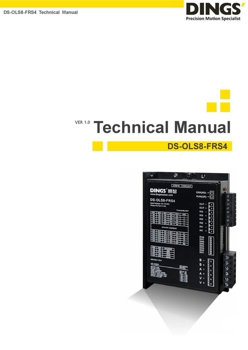
Dings DS-OLBS6-FSC User manual

page│1
Technical Manual
DS-OLBS6-FSC
DS-OLBS6-FSC Manual
VER 1.0

page│2
Table of Contents
1. Specification and Description…..……..…………………………...…………3
2. Product Characteristic..………..…………………..………….….…………..3
3. Terminal Connection…………………………..………………….…………..4
3.1Power Input……………………………………...……………………....4
3.2 Motor Input….…………………………………...………………………4
4. Connection Diagram ofMotor and Driver……………..……………………..4
5. Dimension……………….…….……….………………..……………………...5
6. Functions and Usage...…….……….………………..………………………..5
6.1 Speed Adjustment Method..………………...………………………....5
6.2 Motor Operate / Stop Control (EN)…..………………………………...6
6.3 Motor Rotation Direction Control (F/R).……………………………....6
6.4 Brake the Motor to Stop (BK)………...……...……………………........6
6.5 Speed Signal Output (PG)……………..…………………………….....6
6.6 Alarm Output (ALM)……..……………..…………………………….....6
6.7 Drive Failure……………..……………..…………………………….....7
7. Using……….…….……………………………..………...……………………..7
Click to return to table of contents
Contents

page│3
Summary
This closed-loop speed controller is de
signed with the latest type IGBT and MOS
power devices. It takes advantage of DC brushless motor’
s Hall signal to double
frequency for closed-loop speed control. PID control links with the speed controller.
The control system is stable and reliable, especially at low speed, it always can reach
the maximum torque, The speed control range is from 150 to 10000rpm.
1. Specification and Description
PID speed and current double loop regulator
High performance, low price
20KHZ Chopper frequency
Electrical stop toensure the quickly action of motor
Over load ratio larger then 2, torque always can achieve the max in low speed
Provide OVP, LVP, OCP, OTP, illegal horal signal and other fault alarm.
2. Product Characteristic
Drive model DS-OLBS6-FSC
Input voltage 24 VDC – 48 VDC
Min. Input voltage 12 VDC
Max input voltage 60 VDC
Maximum continuous output current 15 A
Accelerate time constant, default 2sec others can be customized
Warning
*Do not measuring or touch any components without housing while operating.
* Should check soleplate or change fuse 1minter later after power off.
* Operating without housing is forbidden.
* Make sure to connect the ground terminal, otherwise the brushless motor will
working unsteadily
* Sudden damage while drives working, our company only affords the service
and replace in guarantee. Personal injury and motor damage caused by the
accident will invalidate the guarantee.
Specification and Description / Product Characteristic

page│4
3. Terminal Connection
3.1 Power Input
1 V+ 24VDC - 48VDC input
2 GND GND
3.2 Motor Input
1 MA A phase
2 MB B phase
3 MC C phase
4 GND Hall signal power negative
5 HA Hall signal A input
6 HB Hall signal B input
7 HC Hall signal C input
8 +5V Hall signal power positive
4. Connection Diagram of Motor and Driver
Terminal Connection / Connectino Diagram of Motor and Driver

page│5
5. Dimension : 150×97×48mm
6. Functions and Usage
6.1 Speed Adjustment Method
This drive provide below two adjust methods for the user to choose:
Inner potentiometer speed adjustment : rotate the potentiometer on the driver panel
counterclockwise, the rotate speed of the motor will decrease, rotate the potentiometer on
the driver panel clockwise, The rotate speed become higher. If you use external input to
adjust speed, make sure the potentiometer is set in the min. state.
External speed adjustment : Connect on the GND and +5V of the drives, speed can be
adjusted on external potentiometer ((5K~100K) when connect SV terminal. Input simulate
voltage through other control command (e.x. PLC, SCM etc.) to SV terminal to achieve the
speed adjust as well (relative GND). The range of the SV terminal is DC OV~+5V, the
relevant motor speed is 0~rated speed.
External digital signal speed regulation : Add 5V between SV and GND, speed can be
adjusted by PWM control between the 1KHz~2KHz, motor speed is influenced by duty. At
this time, by adjusting the R-SV potentiometer, SV digital signal amplitude can be 0~1.0 ratio
Dimension / Functions and Usage
96.5
151
142
48
P/A
R-SV
5

page│6
attenuation processing. Generally, adjust R-SV to 1.0, SV input digital signal without
attenuation processing.
6.2 Motor Operate / Stop Control (EN)
You can control the brushless motor to run or stop by controlling the terminal “EN” and “GND”
connecting. The motor will running when we connect the terminal “EN” to “GND”; when shut
down, the motor will stop naturally, and the stopping time will decided by the motor inertia
and load add on the motor.
6.3 Motor Rotation Direction Control (F/R)
You can control the motor rotation direction by controlling the terminal “F/R” and “GND”
connection. When connect terminal “F/R” to terminal “GND”, the motor will run at CCW (view
from motor output side), and when shut down, the motor will run at another direction.
Attention
If you need to change the motor rotation direction, please stop the motor at
first, otherwise the driver shall be damaged.
6.4 Brake the Motor to Stop (BK)
You can break the motor to stop if need. The motor will run when the terminal “BK” not
connects to “GND”, but if you connect these two terminals, the motor will stop quickly. And
the motor stopping time will be decided by inertia and load adding on the motor.
Attention
If you are not necessary to stop the motor quickly, please don’t use with this
function since it has some electrical and mechanical impact on the motor and
controller.
6.5 Speed Signal Output (PG)
The speed pulse output is 0C, output 30V/10mA max. You can connect with a resistance
(3K ohm ~10K ohm) between the signal and the input power to get the speed pulse signal.
3xN Output Pulse per revolution, N is pole of motor, Example: 2 pairs of pole motor,12
pulses per revolution, when the motor speed is 500 rev/min, the pulses from PG output
pulses are 6000.
6.6 Alarm Output (ALM)
The alarm output port is 0C, output 30V/10mA max. You can connect with a resistance (3K
ohm ~10K ohm) between the signal and the input power to get the alarm signal. When
Functions and Usage

page│7
alarm, this port and the GND connecting (Low voltage), and the controller will stop working
and keep in alarm status.
6.7 Drive Failure
Over voltage or over current can lead the driver to a protected status, the drive will
automatically stop working, the motor stop and blue light is flashing. As long as you enable
terminal re-reset (EN and GND disconnected) or power Off, the driver will disarm the alarm.
When this failure occurs, please check the motor wire connection.
7. Using
Insure that motor line, hall line and power line connect correct, Motor and driver will be
damaged if lines connected wrong.
When using inner potentiometer speed adjust, connect “EN” with “GND” terminal,
connect SV terminal with 5V terminal, adjust speed by inner potentiometer.
When using external potentiometer to adjust speed: adjust R-SV to 1.0 position,
meanwhile connect EN to GND terminal, connect external potentiometer (middle
connection ) to SV terminal, the other two connect GND and +5V terminal.
Motor will running with highest speed under closed loop, adjust attenuation
potentiometer to get speed commanded.
Functions and Usage / Using

page│8
International
Customer
Person in Charge :
Daniel Jang
daniel@dingsmotion.com
Building 1#, 355 Longjin Road,
Changzhou Economic Development
Zone, Jiangsu, China
+86-519-85177826, 85177827
North America
Customer
Person in Charge :
Nicolas Ha
sales@dingsmotionusa.com
335 Cochrane Circle Morgan Hill,
CA 95037
+1-408-612-4970
China
Customer
Person in Charge :
Sweet Shi
info@dingsmotion.com
Building 1#, 355 Longjin Road,
Changzhou Economic Development
Zone, Jiangsu, China
+86-519-85177826, 85177827
It is prohibited to copyright or replication of the part or whole of user manual without permission.
+86-0519-8517 7825
+86-0519-8517 7807
Building 1#,355 Longjin
Road, Changzhou
Economic Development Zone, Jiangsu, China
www.dingsmotion.com
Table of contents
Other Dings Controllers manuals
Popular Controllers manuals by other brands
Cleco
Cleco DGD mPro400GC Programming manual
TYROLIT Hydrostress
TYROLIT Hydrostress PPH40RR Series operating instructions
Texas Instruments
Texas Instruments TUSB5052 user guide
Vaillant
Vaillant VRT 350 installation instructions
Power Jacks
Power Jacks EMA I Maintenance manual
roco
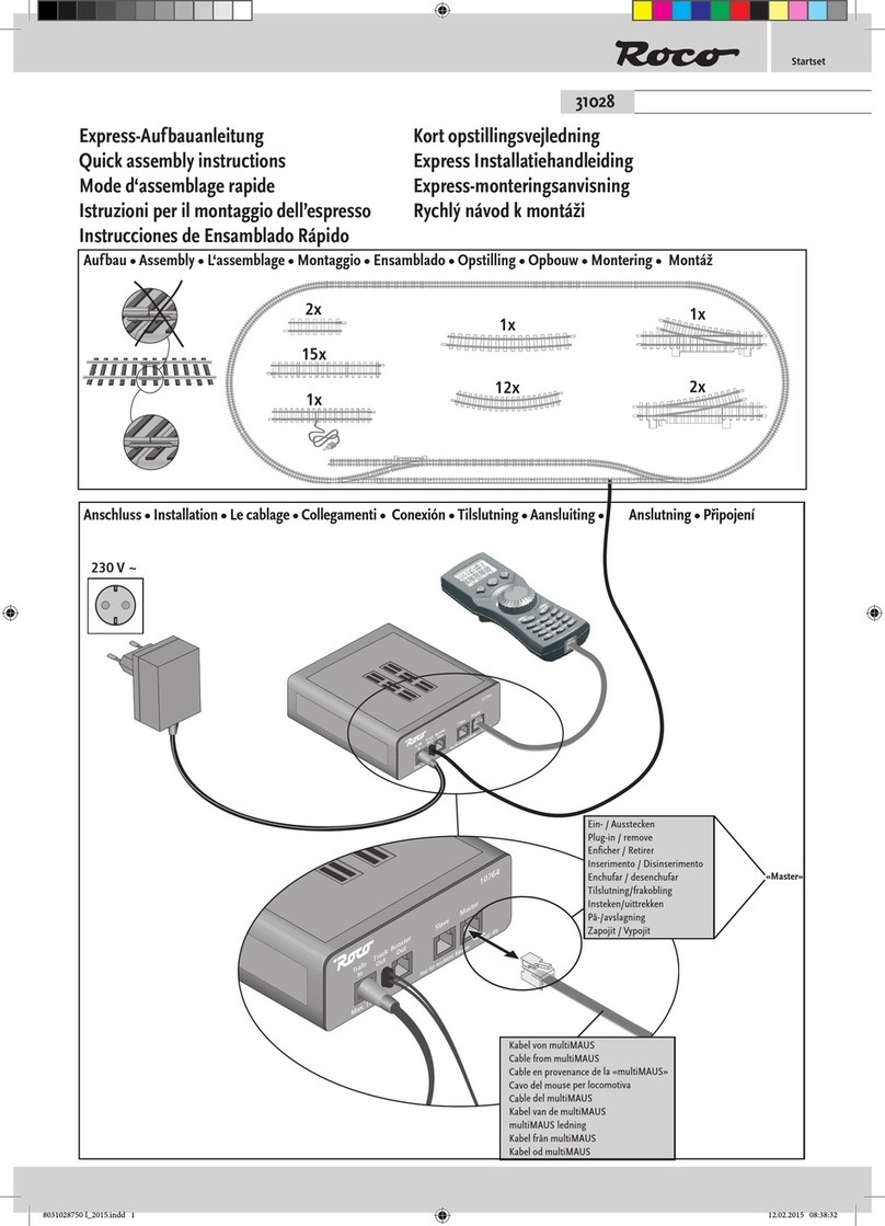
roco 31028 Quick assembly instructions

