Dion-Ag 860 User manual
Forage Blower
Operator’s Manual
Manual no. S5522E032
860
860HO

2MANUAL / MANUEL NO. S5522E032 V1.0
DION-AG INC. LIMITED WARRANTY TERMS AND CONDITIONS
Covered by Warranty – Under the warranty, Dion-Ag guarantees its new machinery and/or equipment to be free of
defects, both in workmanship and material, for a period of one (1) year from the time of delivery by the dealer. Dion-
Ag Inc. will repair or replace, at its discretion and without charge for service parts or labour, any defective part of the
equipment on condition that the machinery and/or equipment has been operated in accordance with the instructions
contained in the Dion-Ag Inc. Operator’s Manual.
Not covered by Warranty – This warranty does not cover: (1) service parts and labour needed to maintain the
unit; and (2) the replacement of parts due to normal wear and tear. The owner is responsible for these items. Some
examples of maintenance and normal wear parts are: oil, lubricants & other uids, belts, knives, clutch and clutch
discs, roller chain, paddles, etc. Dion-Ag Inc. is not responsible for depreciation or damage caused by normal
wear, lack of reasonable and proper maintenance, failure to follow operating instructions, misuse, lack of proper
protection during storage, vandalism, the elements, collision or accident.
Securing Warranty Service – To secure warranty service, the purchaser must report the machinery and/or
equipment defect to an authorized dealer and request warranty service within the applicable warranty terms.
Owner’s Obligation – It is the responsibility of the Owner to transport the equipment to the service shop of an
authorized Dion-Ag Dealer or to reimburse the dealer for any travel or transportation expense involved in fullling
this warranty. This warranty does NOT cover rental of replacement equipment during the repair period, loss of
prots, or other commercial loss, and any or all incidental or consequential damages, overtime labour charges and/
or freight charges for replacement parts.
Limitations of This Warranty – No agent, employee or representative of Dion-Ag Inc. has the authority to
amend, or modify, in any manner whatsoever, the terms of the present warranty. The express warranties herein
contained exclude all other express, implied or statutory warranties. THIS WARRANTY IS IN LIEU OF ALL
OTHER WARRANTIES INCLUDING THE WARRANTIES OF MERCHANTABILITY AND/OR FITNESS FOR ANY
PARTICULAR PURPOSE.
Right to Inspect – Dion-Ag and its authorized agents reserve the right to inspect the purchaser’s Dion-Ag product
to determine if a defect in material or workmanship exists prior the commencement of any covered repairs. It is
the purchaser’s responsibility to ensure availability and/or delivery of the product to Dion-Ag for the purpose of
inspection.
Right to Make Design Changes – Dion-ag reserves the right to make changes in the design and other changes in
its products at any time and from time to time without notice and without incurring any obligation of its part to modify,
improve or add to products previously ordered from Dion-Ag and sold or shipped by Dion-Ag.
Liability – Dion-Ag Inc. shall not be liable, if, during the use of the machinery and/or attachment, the security guards
have been removed, modied, or have not been properly maintained.
The Warranty shall not apply if the instructions mentioned in this manual have not been followed completely and
correctly. Nor will the warranty apply if the owner or any third party modies the machine without Dion-AG’s knowledge
and/or authorization. Every purchaser, when buying a Dion-Ag machine, agrees and undertakes to use and operate
the machinery and its component parts safely, and in accordance with all applicable laws, and in accordance with
the Operator’s Manual. Furthermore, the purchaser agrees and accepts to indemnify and hold harmless Dion-Ag for
all losses and damages to any person or property resulting from the purchaser’s non-compliance with the terms and
conditions of this warranty. Each purchaser further agrees to bring the warranty to the attention of any subsequent
purchaser, and to obtain agreement therein as a condition of resale or transfer.

3
MANUAL / MANUEL NO. S5522E032 V1.0
FORAGE BLOWER
860 - 860HO
TO OUR CUSTOMER
We appreciate your condence in Dion Farm Equipment and thank you for your trust. In preparing this manual, we
hope we have furnished you with a valuable tool for operating and maintaining this ne machine. Use this manual as
your guide. Practicing the instructions given here will result in many years of dependable service from your machine.
Your Dealer can give you assistance with parts and specially trained personnel to assist you in repair and
maintenance.
Call your Dealer if you need any assistance or information.

TABLE OF CONTENTS
4MANUAL / MANUEL NO. S5522E032 V1.0
SPECIFICATIONS........................................................................5
SERIAL NUMBER LOCATION ..............................................................6
CHECK LIST............................................................................7
FOREWORD ............................................................................8
SAFETY RULES .........................................................................9
SAFETY ALERT SYMBOL.........................................................................9
FOLLOW A SAFETY PROGRAM ...................................................................9
A WORD TO THE OPERATOR .....................................................................9
PTO OPERATION ...............................................................................10
RECOMMENDED WORKING AREA.................................................................11
PROCEDURES FOR STOPPING THE FORAGE BLOWER...............................................12
GUARDS AND SHIELDS..........................................................................12
SAFETY SIGNS.................................................................................13
SAFETY SIGN APPLICATION PROCEDURE ..........................................................14
ASSEMBLY INSTRUCTIONS...............................................................16
DRIVELINE ASSEMBLY INSTRUCTIONS ............................................................16
1000 RPM GEARBOX INSTALLATION PROCEDURE ...................................................18
HYDRAULIC WHEEL INSTALLATION INSTRUCTIONS..................................................22
OPERATING INSTRUCTIONS ..............................................................26
DRIVELINE SHAFT ALIGNMENT ..................................................................26
RUNNING SPEED ..............................................................................26
WHEEL LIFT SYSTEM...........................................................................27
TRANSPORTING INSTRUCTIONS ................................................................27
FORAGE BLOWER LIFTING HOOKS...............................................................29
MAINTENANCE DOOR ..........................................................................29
WATER SYSTEM...............................................................................29
SPEED REDUCER .............................................................................30
HYDRAULIC WHEEL SYSTEM (OPTION)...........................................................31
LUBRICATION ..........................................................................32
DRIVELINE .....................................................................................32
SPEED REDUCER ...............................................................................32
LUBRICATION CHART ............................................................................32
ADJUSTMENTS & MAINTENANCE .........................................................35
ROTATING OUTLET ..............................................................................35
FAN ADJUSTMENT...............................................................................35
SPOUT KNIFE ADJUSTMENT ......................................................................36
FAN BLADE REPLACEMENT .......................................................................38
INSTRUCTIONS FOR REASSEMBLING THE FAN SHAFT................................................39
DRIVELINE SHEAR BOLTS ........................................................................41
AUGER ADJUSTMENT ............................................................................41
REVERSIBLE CONTOUR REPLACEMENT ............................................................42
AUGER INTERMEDIATE BELT TENSION .............................................................43
AUGER DRIVE BELT TENSION .....................................................................43
AUGER BELT REPLACEMENT. . . . . . . . . . . . . . . . . . . . . . . . . . . . . . . . . . . . . . . . . . . . . . . . . . . . . . . . . . . . . . . . . . . . . .44
AUGER BRAKE..................................................................................44
AIR INTAKE CONTROL............................................................................44
SUGGESTED INITIAL AIR INTAKE ADJUSTMENTS .....................................................45
DISMANTLING AND REASSEMBLY OF DRIVELINE ROTATING GUARDS ...................................45
ECCENTRIC LOCKING COLLAR INSTALLATION .......................................................45
SPEED REDUCER ...............................................................................46
CHAIN TENSION CHECK ..........................................................................46
CHAIN TENSION ADJUSTMENT ....................................................................46
ALIGNMENT AND ADJUSTMENT OF THE SPEED REDUCER.............................................47
ASSEMBLING THE WHEEL HUBS...................................................................48
STORAGE..............................................................................49
TROUBLESHOOTING ....................................................................50

SPECIFICATIONS
5
MANUAL / MANUEL NO. S5522E032 V1.0
Specications and design are subject to change without notice and without liability from the
manufacturer therefore.
MAIN FAN
Main fan ............................................................................ 59” (150cm)
Blades................................................................................ 8
RPM................................................................................... 540
RPM (with reducer)............................................................ 650
Speed at blade tip:
540 RPM............................................................................ 8340 ft/min. (ft/min) (2542m/m)
650 RPM............................................................................ 10038 ft/min. (ft/min) (3060m/m)
MAIN AUGER
Length................................................................................ 55” (140cm)
Diameter............................................................................ 14” (36cm)
Pitch.............................................. 14” (35.5cm)
RPM................................................................................... 500
RPM (with reducer)............................................................ 601
Overall length with pole ..................................................... 129” (378cm)
Overall width...................................................................... 84” (213cm)
Overall height when operating (wheels lowered)............... 72.5” (184cm)
DRUM OUTLET HEIGHT
Transport position.............................................................. 70” (178cm)
Operating position (wheels lowered) ................................. 61” (155cm)
HOPPER
Height (operating position) ................................................ 21” (53cm)
Inlet width .......................................................................... 42” (107cm)
Inlet depth.......................................................................... 30” (76cm)
Tires................................................................................... 18.5 X 8.5-8
Weight ............................................................................... 1350 lbs (610Kg)
RECOMMENDED TRACTOR POWER
540 RPM - 14” dia. auger ................................................. 60 to 160 HP
1000 RPM - 14” dia. auger ............................................... 130 to 200 HP
RECOMMENDED DRIVELINE
540 RPM: Tractor under 160 HP, use a T80 driveline
Tractor over 160 HP, use a T90 driveline
1000 RPM: Tractor under 210 HP, use a T80 driveline
Tractor over 210 HP, use a T90 driveline

SERIAL NUMBER LOCATION
6MANUAL / MANUEL NO. S5522E032 V1.0
For your convenience, write down in full in this manual both the model and serial numbers of your machine, as
shown on the name plate illustrated below. Always mention both the model and the serial numbers when ordering
parts or regarding any other correspondence referring to your machine.
Write down your number here:
MODEL NO. SERIAL NUMBER
R.H.
REAR
L.H
FRONT
WARNING
MAXIMUM SPEED LIMIT 15
M.P.H
VITESSE MAXIMALE 25
K.P.H
ATTENTION
MADE IN CANADA
DION-AG INC.
BOISBRIAND QUE.
MODEL NO.
SERIAL NO.
- Ag Inc.
MADE IN CANADA
DION-AG INC.
BOISBRIAND QUE.
MODEL NO.
SERIAL NO.
- Ag Inc.

CHECK LIST
7
MANUAL / MANUEL NO. S5522E032 V1.0
PRESEASON CHECKS
❑Check auger brake.
❑Check tension of belts. Check all sheaves for correct alignment.
❑Check all adjustable components for correct setting (blower and auger).
❑Check tire pressure. See specications.
❑Check wheel bolts. They should be tighten to a recommended torque of 85 to 95 lbs/ft.
❑Perform complete lubrication and servicing of the machine according to Servicing. Make sure all grease
ttings are in place and taking grease properly. Check transmission uid levels if you have the option.
❑Check transmission chain tension
❑Look for loose or missing bolts and parts.
❑Run the machine in a stationary position at half-speed for a short period of time. Shut off tractor engine.
Make sure all moving parts have stopped, then inspect bearings for over-heating, excessive wear, or
loose anges and lock collars.
❑Make sure the proper operating adjustments have been made, taking into account the harvest conditions.
❑Make sure all shields are installed. Review Safety Precautions.
❑Make sure all safety decals are readable and in good condition.
❑Check for wear on parts (paddles, blower and auger bottoms, etc.).
❑Make sure holes for the injection of water in the fan and the feed table are not obstructed.
DAILY CHECKS
❑Check auger brake
❑Remove all crop residue and wipe off oil and dirt.
❑Lubricate and service the machine according to the Servicing section.
❑Check chain and belt tension. Check all sheaves for correct alignment.
❑Check tire pressure. See Specications.
❑Make sure Blower is hooked to tractor correctly, and that the safety chain is installed
securely. Make sure all controls are operable.
❑Make sure that all shields are in good condition on the blower (with special attention to the driveline
shields).

FOREWORD
8MANUAL / MANUEL NO. S5522E032 V1.0
TO OUR CUSTOMER
The following pages and illustrations are printed to help
supply you with the knowledge to better operate and
service your Dion Forage Blower.
Any piece of equipment needs, and must have a certain
amount of service and maintenance to keep it in top
running condition. We have attempted to cover all the
adjustments required to t most conditions; however,
there may be times when special care must be taken to
t a condition.
Study this operator’s manual carefully and become
acquainted with all the adjustments and operating
procedures before attempting to operate your new
equipment. Remember, it is a machine and it has been
designed and tested to do an efcient job in most
operating conditions and will perform in relation to the
service it receives.
If special attention is required for some conditions, ask
your Dion Dealer; his parts and Service Organization will
be glad to help and answer any questions on operation
and service of your new machine.
THIS MANUAL SHOULD REMAIN WITH
THE MACHINE WHEN SOLD
This manual was prepared from the latest product
information available at publication time. The Company
reserves the right to make changes at any time without
notice.
The safety section of your Operator’s manual is intended
to point out some of the basic safety situations which
may be encountered during the normal operation and
maintenance of your Forage Blower, and to suggest
possible ways of dealing with these situations. This
section is NOT a replacement for other safety practices
featured in other sections of this book.
WARRANTY INFORMATION
Your Dion Warranty for this machine appears on your
copy of the Retail Purchase Order and Warranty Terms
and Conditions Statement which you received from your
dealer when you purchased the Blower.
As indicated on the Retail Purchase Order signed by
you and your dealer, you, the equipment purchaser,
shall assume charges for service calls or transportation
of equipment to and from the location of servicing Dion
dealer.
SAFETY
The safety of the operator is one of the main concerns
in designing and developing a new Forage Blower.
Designers build in as many safety features as possible.
However, accidents still occur, which can be avoided by
proper thinking and a more careful approach to handling
farm machinery and implements.
Read and implement the safety instructions detailed in
the safety section of this manual.

SAFETY RULES
9
SAFETY ALERT SYMBOL
The symbol above calls your attention to instructions
concerning your personal safety. It is found throughout
the manual as well as on the machine to point out
specic hazards and ways to avoid them. Always follow
the instructions to minimize the risk of personal injury or
death.
DANGER, WARNING AND CAUTION
Whenever you see the words and symbols shown below,
used in this manual and on decals, you MUST take note
of their instructions as they relate to personal safety.
DANGER: Indicates an imminently hazardous
situation that, if not avoided, will result in DEATH
OR VERY SERIOUS INJURY.
WARNING: Indicates a potentially hazardous
situation that, if not avoided, could result in
DEATH OR SERIOUS INJURY.
CAUTION: Indicates a potentially hazardous
situation that, if not avoided, may result in MINOR
INJURY.
IMPORTANT: The word IMPORTANT is used to identify
special instructions or procedure which, if not strictly
observed, could result in damage to, or destruction of
the machine, process or its surroundings.
NOTE: The word NOTE is used to indicate points of
interest for more efcient and convenient repair
or operation
SIGNS
WARNING: DO NOT remove or obscure Danger,
Warning, Caution safety signs or Instruction
signs that are not readable or are missing.
Replacement signs are available from your
Dealer in the event of loss or damage. The actual
location of these Safety signs is illustrated on
page 14.
FOLLOW A SAFETY PROGRAM
For proper operation of a Forage Blower, you must be
a qualied and authorized operator. To be qualied,
you must read and understand the written instructions
supplied in this Operator’s Manual, have training, and
know the safety rules and regulations for the job.
Some local regulations specify that no one under the
age of 16 years old, for example, may operate power
machinery. This includes tractors. It is your responsibility
to know what these regulations are, and obey them, in
the operating area or situation. These will include, but
are not limited to, the following instructions for proper
operation
WARNING: An operator should not use alcohol
or drugs which can change their alertness or co-
ordination. An operator on prescription or “over
the counter” drugs needs medical advice on
whether he or she can properly operate machines.
A WORD TO THE OPERATOR
It is YOUR responsibility to read and understand the
safety section in this manual before operating your
machine. You must follow these safety instructions that
take you step by step through your working day.
In reading this section, you will note that illustrations
have been used to highlight certain situations. Each
illustration is numbered and the same number appears
in the text in parenthesis. This number is placed at the
end of the written text that refers to the illustration.
Remember that YOU are the key to proper operation of
the machinery. Good safety practices not only protect
you, but also the people around you. Study the features
in this manual and make them a working part of your
safety program. Keep in mind that this safety section is
written only for this type of machine. Practice all other
usual and customary working precautions, and above all.
REMEMBER - SAFETY IS YOUR RESPONSIBILITY.
YOU CAN PREVENT SERIOUS INJURY OR DEATH.
WARNING: In some of the illustrations used in this
Operator Instruction Book, panels or guards may
have been removed for clarity. Never operate the
machine without these components in position.
If the removal of panels or guards is necessary
to make a repair, they MUST be replaced before
operation.

SAFETY RULES
10
• Wear appropriate clothing, safety boots or shoes.
Do not operate the machine when visibility is bad, or
during night, in poor lighting.
• Keep children away from the machine at all times.
• Carefully read all safety signs applied on the machine.
If they are damaged, replace them immediately.
• Keep hands and clothes away from all moving parts.
• Never lubricate or clean any part while the machine
or tractor engine is running.
• If a feeding or throwing mechanism should become
jammed, never attempt to unblock it or remove any
material when the machine is in motion or the tractor
engine running.
• Never remove guards or make adjustments while the
machine or tractor engine is running.
• Before starting the tractor engine, make sure all
guards, shields, and doors are in place and properly
secured and check the machine thoroughly for
possible loose parts or bolts and tighten them.
• Be very careful when adjusting the fan blades and
hopper auger.
• Before operating make sure that all projection pipes
are properly fastened..
• Keep hands and feet out of hopper when the driveline
is coupled to the tractor and the tractor engine is
running.
• Do not climb over or around the hopper when the
forage blower is in operation.
• If it is necessary to enter a silo, make sure it is well
ventilated.
• Always keep the forage blower hitch pinned to tractor
draw bar when operating.
• Make sure all rotating parts are stopped and the tractor
engine is turned off before cleaning or servicing fan
and conduct.
• After having performed any adjustments, be sure that
there are no tools in or on the machine.
• When proceeding onto a public road, always use a
safety chain with a minimum load of 6400 lbs (2910
kg) equipped with a identication plate and a hook
with safety lock.
• When proceeding onto a public road with a Blower
equipped with an hydraulic lift system, always close
the two safety valves (see Figure 40 on page 31).
• Always make sure wheel bolts are well tighten before
proceeding onto a public road. The recommended
torque is 85 to 95 lbs/ft.
• Always install the manual jack (item 7 in Figure 33
on page 28), before uncoupling the Blower with a
1000 RPM transmission.
PTO OPERATION
• POWER-TAKE-OFF DRIVE - Before starting the
tractor engine make sure that the PTO driveline
locking device is properly engaged onto both the
tractor and equipment drive shafts.
• Never wear loose clothing and keep people,
especially children away from the driveline.
• Do not connect a tractor with a PTO speed of 540
RPM on a machine equipped with a 1000 RPM drive.
Do not connect a tractor with a PTO speed of 1000
RPM on a machine equipped with a 540 RPM drive.
• Never proceed to the starting of the machine before
making sure all PTO, machine and tractor shields are
well installed in place.
• The PTO driveline shields should turn freely, be well
connected and kept in good condition.
• Never step across any PTO driveline.
• Never use the PTO driveline as a step.
• Keep at least your height away from a rotating
driveline.
SAFETY RULES
11
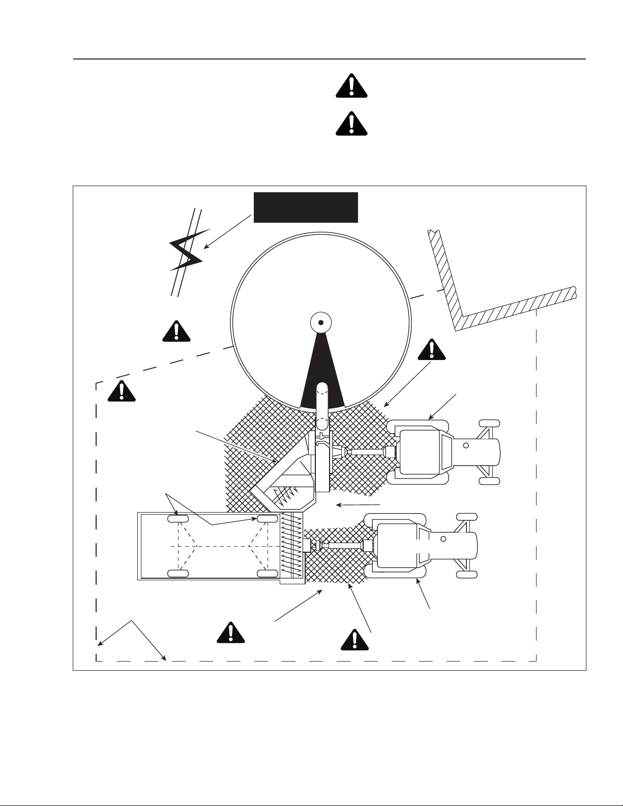
RECOMMENDED WORKING AREA
FIGURE 1
The diagram in Figure 1 shows the recommended
working area. It should be marked off with colored nylon
or plastic ropes as portable barriers to dene exactly the
designated working areas.
WARNING: To prevent personal injury, keep
all persons out of the working area.
WARNING: To prevent personal injury, the
work area must be smooth, clean and free of
debris and tools.
WORK ZONE
AUGER INTAKE AREA
PTO DRIVE AREA
PTO DRIVE AREA
BARN
OPERATOR AREA
BLOCKED WHEELS
BLOCKED
WHEELS
BLOCKED WHEELS
OPERATING AREA
KEEP CLEAN
TRACTOR
BEATER
BLOWER LOWERED
TO THE GROUND
AND STABILIZED
OVERHEAD WIRES
KEEP AWAY
Figure 1 Typical working area diagram
SAFETY RULES
12
PROCEDURES FOR STOPPING THE
FORAGE BLOWER
WARNING: To prevent personal injuries, do not
perform any kind of maintenance work while the
machine is running.
Before cleaning, adjusting, or greasing, the following
procedures should be followed to stop the Forage
Blower:
1. Disengage the tractor PTO.
2. Stop the tractor engine.
3. Set parking brake and remove the key.
4. Wait until all rotating movements have come to a
complete stop.
5. Remove the PTO chain.
6. Remove the driveline from the tractor output shaft
and attach it on its special support.
WARNING: Secure the PTO driveline to the
support to prevent rotation of the fan or auger.
7. Block all equipment wheels.
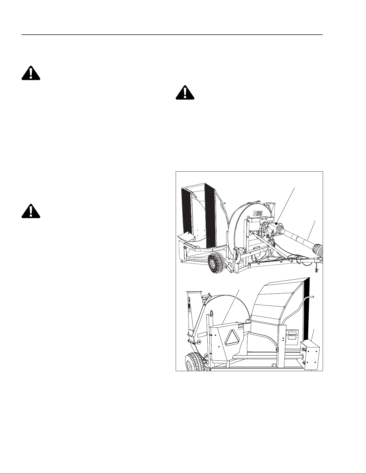
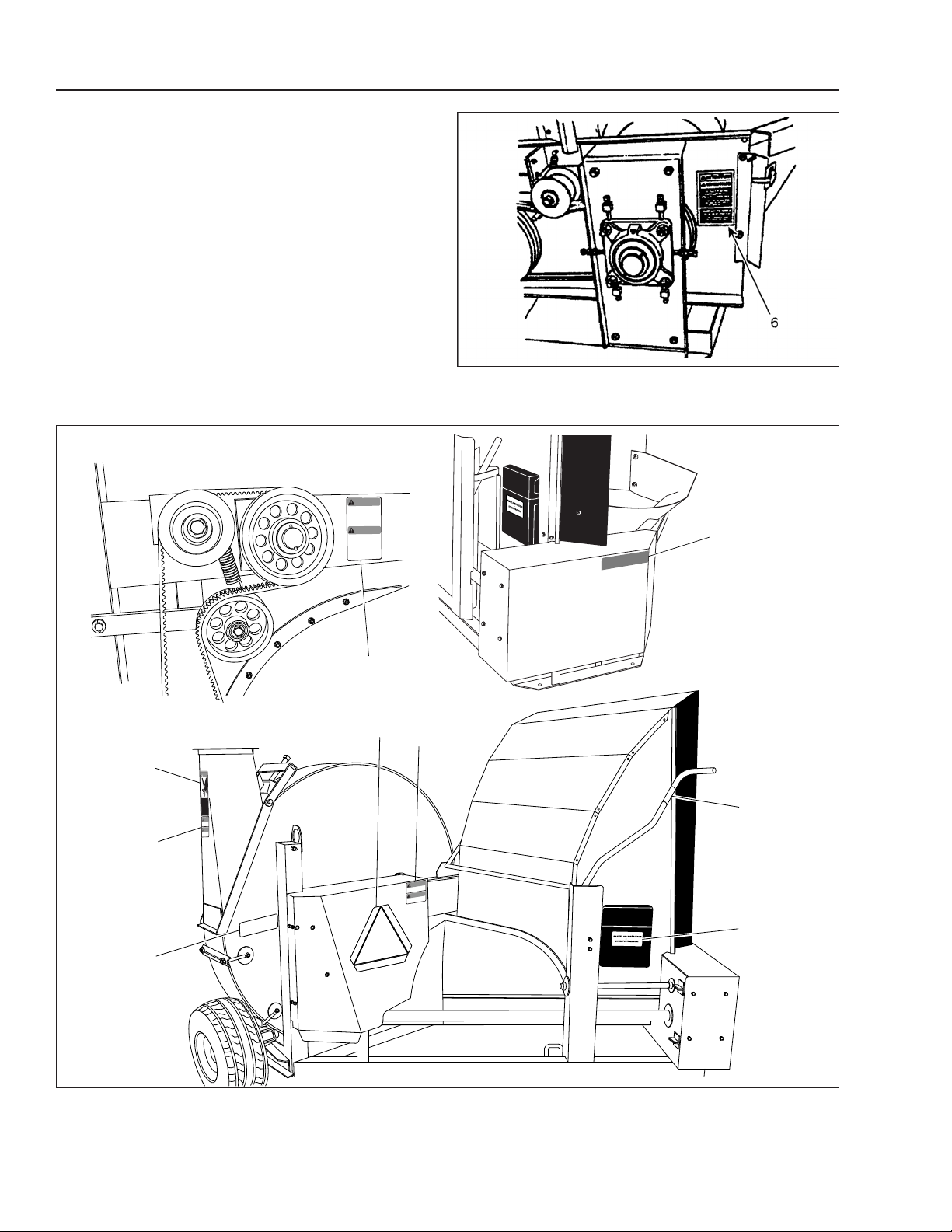
GUARDS AND SHIELDS - FIGURE 2
The Forage Blower is equipped with guards and shields
at various locations. Observe the safety signs and follow
their instructions.
All guards and shields factory installed should be
in place and maintained in good condition.
1. The telescopic driveline which couples to the tractor
is covered with a rotating shield (item 1).
2. A hinged guard covers the driveline (item 2).
3. A hinged guard covers the belt mechanism, driving
the hopper auger (item 3).
4. A hinged guard covers the main fan rear mechanism
(item 4).
1
3
2
4
WARNING
ATTENTION
DONOTOPENWHILE
MACHINEISINOPERATION
ARRÊTERLEMÉCANISME
AVANTD’OUVRIR
B58-24830
WARNING
ATTENTION
DONOTOPENWHILE
MACHINEISINOPERATION
ARRÊTERLEMÉCANISME
AVANTD’OUVRIR
B58-24830
DANGER
ILYA DES PIÈCE ROTATIVESÀ
L’INTÉRIEURDECETTE OUVERTURE.
ARRÊTERLEMO TEUR DU TRACTEUR
ETDÉSENGAGERLA PRISE DE FORCE.
ATTENDREQUETOUT MOUVEMENT
SOITARRÊTÉAVANTD’AJUSTER OU
DENETTOYER
ROTATINGPARTSINSIDE THIS
OPENING.SHUTOFF TRACTOR ENGINE
ANDDISENGAGEPOWER TAKE OFF
ANDWAITFOR ALL THE MO TIONS TO
STOPBEFORECLEANINFG OR
SERVICING
Figure 2
Guards and shields
SAFETY DECALS
13
MANUAL / MANUEL NO. S5522E032 V1.0
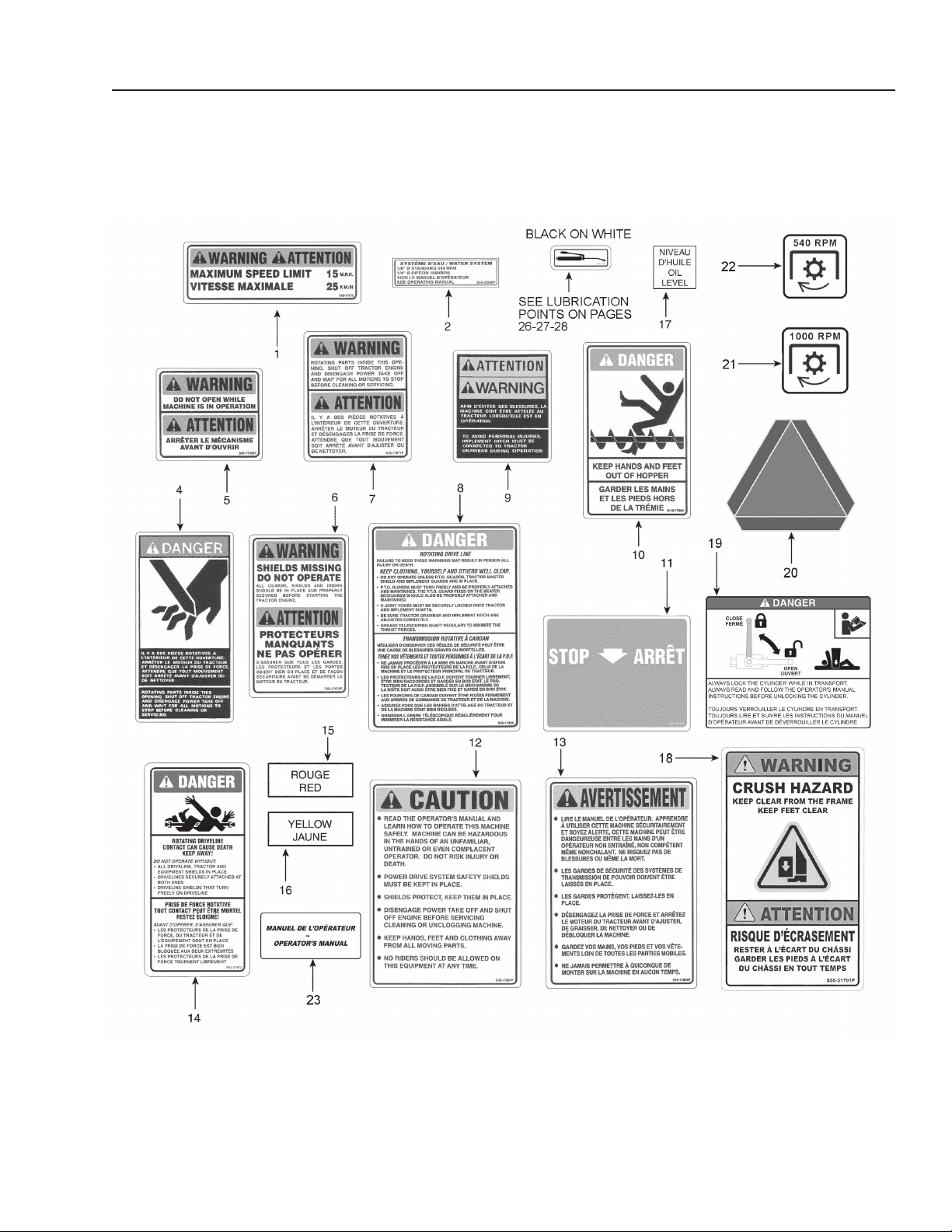
SAFETY SIGNS - FIGURE 3
NOTE: All safety signs should be kept as clean and free
of dust as possible.
NOTE: When safety signs are worn or if machine is
repainted, order a complete kit of safety signs.
Figure 3 Safety decals
SAFETY DECALS
14 MANUAL / MANUEL NO. S5522E032 V1.0
SAFETY SIGN APPLICATION PROCEDURE
FIGURE 4, FIGURE 5 AND FIGURE 6
1. The surface should be free from dirt, grease, earth,
or any other foreign material.
2. When the surface is dry, remove a portion of the
backing paper and apply the decal in part and align
its position as per the surrounding parts. Slowly peel
off the remaining backing paper and apply hand
pressure.
3. Press slightly on the surface of the safety sign to
remove all air bubbles.
Figure 4 Safety sign locations
6
4
7
15
5
20
15
23
11
WARNING
ATTENTION
ALLGUARDS, SHILEDSANDDOORS
SHOUILDBE IN PLACEANSPROPERLY
SECURTEDBEDORESTARTINGTHE
TRACTORENGINE
SHIELDS MISSING
DO NOT OPERATE
S’ASSURERQUETOUSLES GARDES,
LESPROTECTEURSETLES PORTES
SOIENT BIENENPLACEET DE FAÇON
SÉCURITAIREAVANTDEDÉMARRERLE
MOTEUR DUTRACTEUR
PROTECTEURS
MANQUANTS
NE PAS OPÉRER
WARNING
ATTENTION
DONOTOPEN WHILE
MACHINE IS INOPERATION
ARRÊTER LE MÉCANISME
AVANT D’OUVRIR
B58-24830
WARNING
ATTENTION
DONOTOPEN WHILE
MACHINE IS INOPERATION
ARRÊTERLEMÉCANISME
AVANT D’OUVRIR
B58-24830
DANGER
ILY ADES PIÈCE ROTATIVES À
L’INTÉRIEURDE CETTE OUVERTURE.
ARRÊTERLE MOTEUR DU TRACTEUR
ETDÉSENGAGER LA PRISE DE FORCE.
ATTENDREQUE TOUT MOUVEMENT
SOITARRÊTÉ AVANTD’AJUSTER OU
DENETTOYER
ROTATINGPARTSINSIDE THIS
OPENING.SHUT OFF TRACTOR ENGINE
ANDDISENGAGE POWER TAKE OFF
ANDWAIT FOR ALL THE MOTIONS TO
STOPBEFORE CLEANINFG OR
SERVICING
Figure 5 Safety sign locations

SAFETY DECALS
15
MANUAL / MANUEL NO. S5522E032 V1.0
10
16
2
8
13
17
19
21-22
9
4
1
7
18
19
18
18-19
19
5
12
5
14
11
7
Figure 6 Safety sign locations
ASSEMBLY INSTRUCTIONS
16 MANUAL / MANUEL NO. S5522E032 V1.0
DRIVELINE ASSEMBLY INSTRUCTIONS
FIGURE 7 TO FIGURE 12
Remove all cables and/or wires used for transportation.
Attach the draw bar to the Forage Blower main frame
using bolts (item 4) already installed. Do not tighten
these bolts.
Attach the turnbuckle (item 5) to the Forage Blower
using the bolts (item 6) already in place. Adjust the draw
bar height in relation to the tractor.
Carry out this adjustment making sure both the Forage
Blower and the tractor are on a level terrain (see Figure
30 on page 26).
Tighten the draw bar lock nuts (item 4) and the turnbuckle
lock nuts (item 6) by applying a light pressure.
7
6
4
45
6
Figure 7
Open the driveline guard (item 7) then slide and bolt the
driveline to the fan shaft (item 9). Secure using the locks
(item 10). Tighten bolts (item 8) to
103 N-m then
close
the guard.
7
88
9
10
Figure 8 Assembling the driveline
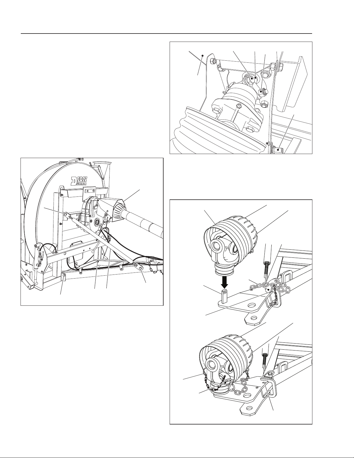
Place the end of the 540-1000 RPM driveline (item 1) that
connects to the tractor in its support (item 2), then secure
with the special lock (item 3) which is itself secured with a
safety spring pin (item 4)
.
1
2
5
5
3
3
4
Figure 9 Assembling the driveline

ASSEMBLY INSTRUCTIONS
17
MANUAL / MANUEL NO. S5522E032 V1.0
Figure 10 Driveline
Lubricate the Forage Blower (refer to the lubrication
Instructions) and make sure that all rotating parts move
freely.
When the PTO is hitched to the tractor, insert the special
lock in the hole (item 5 in Figure 9) provided for that
purpose.
WARNING: Always install the manual jack (item
12) when the 1000 RPM Blower is not hitched to
the tractor.
12
Figure 11 Manual jack in place
CAUTION: The driveline should never extend
beyond 63” (1,6 m) that is when measured from
both of its ends.
Adjust the Blower draw bar according to the RPM, either
540 or 1000 RPM, as shown below. Refer to Figure 33
on page 28. Use the two bolts already in place (item 1
in Figure 12) with lock nuts. Tighten well.
1000 540
1000 540
540 RPM
1000 RPM
(CHOICE BETWEEN 2 POSITIONS)
POSITION 1 POSITION 2
1
1
Figure 12 Draw bar adjustment
To Blower
To tractor

ASSEMBLY INSTRUCTIONS
18 MANUAL / MANUEL NO. S5522E032 V1.0
NOTE: Must be installed on a blower with main shaft
specially designed for a 1000 rpm transmission
(without grooves, for driveline anchor bolt)
1. Remove driveline and guard (item 1).
2. Remove the two nuts (item 2), insert the two 1/2”
dia. lock washers (item 18) then install the U-shaped
support bracket (item 8).
NOTE: On the model with hydraulic lift, the U-shaped
support bracket (item 8) is already in place.
3. Fasten the top plate (item 3) to the gearbox using
the four 1/2” X 1 1/4” lg bolts and the four 1/2” lock
washers.
4. Fasten the lower plate (item 4) to the gearbox using
the three 5/16” X 5 1/2” lg bolts (item 20), twelve
5/16” washers (item 6) (the number of washers can
vary according the nal adjustment), three 5/16” lock
nuts (item 21) and three spacers (item 14).
NOTE: The 12 washers (item 6) must be inserted
between the plate (item 4) and the gearbox as
needed. These washers will set the gearbox
parallel to the machine frame and thus avoiding
any pressure on the drive shaft.
5. Slide the gearbox onto the shaft (item 5).
6. Align the gearbox as shown on page 47.
7. Re-adjust the lower plate (item 4) with the at
washers (item 6).
8. Fasten the plate (item 7) to the lower plate (item 4)
and to the U-shaped support bracket (item 8) with
two 5/8” X 1 1/2” lg hex head bolt (item 15), two lock
washers and two 5/8” nuts.
9. Install the upper elbow (item 9) in the appropriate
hole of the housing. Use Teon tape.
10. Screw the four 5/8” X 1 1/2” lg bolts (item 15) with
four 5/8” nuts to the plate (item 11).
11. Install the plate (item 11) to the gearbox using the
two 1/2” X 1 1/4” bolts and two lock washers.
12. Install the lower elbow (item 12) and the coupling
(item 10). Use teon tape.
13. Fill up the gearbox with oil. Pour oil into the upper
elbow (item 9) until the oil comes out of the lower
elbow (item 12). Follow recommendations on page
34.
14. Screw the cap (item 17) to the elbow.
15. Install the breather (item 13).
16. Install the guard (item 1) with four 5/8” nuts.
17. Install the driveline.
18. Install the guard (item 16).
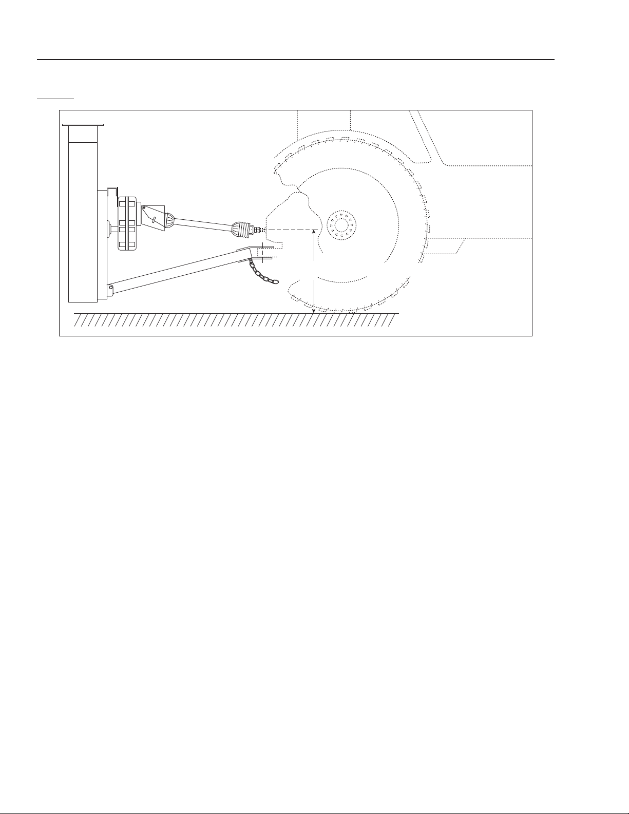
1000 RPM GEARBOX INSTALLATION PROCEDURE WHEN TRACTOR’S PTO SHAFT IS
LESS THAN 30” (76 CM) FROM THE GROUND - FIGURE 13 AND FIGURE 14
< 30” (76 cm) from the ground
Figure 13 Tractor PTO shaft at less than 30” from the ground

ASSEMBLY INSTRUCTIONS
19
MANUAL / MANUEL NO. S5522E032 V1.0
1
1
12
17
10
9
13
16
18
18
14
5
6
3
24
4
8
15
15
11
7
8
20
Figure 14 Assembling the 1000 RPM gearbox
ASSEMBLY INSTRUCTIONS
20 MANUAL / MANUEL NO. S5522E032 V1.0
1000 RPM GEARBOX INSTALLATION PROCEDURE WHEN TRACTOR’S PTO SHAFT IS
MORE THAN 30” (76 CM) FROM THE GROUND - FIGURE 15 AND FIGURE 16
> 30” (76 cm) from the ground
Figure 15 Tractor PTO shaft at more than 30” from the ground
NOTE: Must be installed on a blower with main shaft
specially designed for a 1000 rpm transmission
(without grooves, for driveline anchor bolt)
1. Remove driveline and guard (item 1).
2. Remove the two nuts (item 2), insert the two 1/2”
dia. lock washers (item 18) then install the U-shaped
support bracket (item 8).
3. Fasten the lower plate (item 4) to the gearbox using
the four 1/2” X 1 1/4” lg bolts and the four 1/2” lock
washers.
4. Fasten the upper plate (item 4) to the gearbox using
the three 5/16” X 5 1/2” lg bolts (item 20), twelve
5/16” washers (item 6) (the number of washers can
vary according the nal adjustment), three 5/16” lock
nuts (item 21) and three spacers (item 14).
NOTE: The 12 washers (item 6) must be inserted
between the plate (item 4) and the gearbox as
needed. These washers will set the gearbox
parallel to the machine frame and thus avoiding
any pressure on the drive shaft.
5. Slide the gearbox onto the shaft (item 5).
6. Align the gearbox as shown on page 47.
7. Re-adjust the upper plate (item 3) with the at
washers (item 6).
8. Fasten the plate (item 7) to the plate (item 3) and to
the U-shaped support bracket (item 8) with two 5/8”
X 1 1/2” lg hex head bolt (item 15), two lock washers
and two 5/8” nuts.
9. Install the lower elbow (item 9) and coupling (item
10) in the appropriate hole of the housing. Use teon
tape.
10. Screw the adapter (item 19).
11. Screw the four 5/8” X 1 1/2” lg bolts (item 15) with
four 5/8” nuts to the plate (item 11).
12. Install the plate (item 11) to the gearbox using the
two 1/2” X 1 1/4” bolts and two lock washers.
13. Install the upper elbow (item 12) and the coupling
(item 10). Use teon tape.
14. Fill up the gearbox with oil. Pour oil into the upper
elbow (item 12) until the oil comes out of the lower
elbow (item 9). Follow recommendations on page
34.
15. Screw cap (item 17) to the adapter (item 10).
16. Install the breather (item 13).
17. Install the guard (item 1) with four 5/8” nuts.
18. Install the driveline.
This manual suits for next models
1
Table of contents
Other Dion-Ag Blower manuals

Popular Blower manuals by other brands


Stihl
Stihl BR 450 instruction manual

Echo
Echo PB-251E - PARTS CATALOG SN P06113001001-P06113999999 REV... parts catalog

Lavorwash
Lavorwash SWL R 950 owner's guide

Delhi Industries
Delhi Industries BI Series Operation instructions and parts manual

Mantis
Mantis BBLOW40-25 Series Operator's & parts manual

Central Machinery
Central Machinery 99989 Assembly, operating, and maintenance instructions