Directed Electronics Soloist Desktop Docking Station User manual

Universal Sound System
Owner’s Guide
/
/
// /
/ /
Stiletto 10/100/2
Starmate 3/4
Sportster 3/4/5
Stratus 3/4


Desktop Docking Station
© Directed Electronics, all rights reserved. 3
Soloist Universal Sound System
Table of Contents
Safety Precautions and FCC Statement 5
Congratulations 6
How to Use this Guide 6
Box Contents 7
Unpacking and Setting up your Soloist
Battery Installation 8
Front View 9
Rear View 10
Remote Control 11
Docking Cradle Types 12
Before inserting the Stiletto Cradle 13
Inserting Docking Cradle 14
Setting the Clock 15
LCD Contrast Setting 16
Installing the Windowsill Antenna 17
Using your Soloist
Switching Soloist On and Off 18
Selecting a Source 18
Volume Control 19
Equalization Settings 19
Dynamic Bass Boost 19
Mute 20
Display Option 20
Using the Headphone Jack 20
Using Specific Sources
Sirius Satellite Radio 20
iPod Music Players 23
Line In/Aux In 24
Alarms and Timers
Alarm Clock 24
Music Timer 26
Sleep Timer 29
USB Communication 30
Specifications 31
Warranty 33


Desktop Docking Station
© Directed Electronics, all rights reserved. 5
Soloist Universal Sound System
Safety Precautions
Take the following precautions to keep Soloist in proper working order:
❍Set up must be performed according to this manual. Directed Electronics is not responsible for issues arising from set
up not performed according to the procedures in this manual.
❍Do not use any power supply other than the one included. This will damage or cause Soloist to be inoperable.
❍Do not use Soloist where it will be exposed to high levels of humidity, moisture, or dust.
FCC NOTICE:
This device complies with Part 15 of FCC rules. Operation is subject to the following conditions:
(1) This device may not cause harmful interference, and
(2) This device must accept any interference received, including interference that may cause undesired
operation. Changes or modifications not expressly approved by the party responsible for compliance could
void the user’s authority to operate this device.
Directed Electronics is not responsible for any radio or TV interference caused by unauthorized modifica-
tions to this equipment. Such modifications could void the User’s authority to operate the equipment.

© Directed Electronics, all rights reserved.
6
Congratulations
Thanks for purchasing Soloist Universal Sound System. This elegant powered speaker system with its unique interchange-
able cradle system will allow you to enjoy high quality audio from SIRIUS Satellite Radio, the ubiquitous iPod portable media
player, and many other popular digital audio and video devices. Be sure to save your sales receipt. It is your best record of
the date of purchase, which is required for warranty service. Read and follow all cautions, warnings and notes. For the latest
information about this and other products, visit www.directedsirius.com. For technical help regarding this product please
contact Directed Electronics at 1-800-753-0800.
How to Use this Guide
Button icons:
Soloist has buttons that are used to control the features
and functions of the system. In addition, an infrared remote
control is provided to control Soloist. Some buttons exist
only on Soloist or the remote, while some buttons exist in
both places.
In order to make this guide easy to understand, icons that
look just like the buttons on Soloist and the remote control
are used in the text.
An icon like this
LINE
AUX
SNOOZE
SLEEP
POWER
SOURCE
MUTE TIMER
MENU
PROG/
CLOCK
+
_
ON
OFF
refers to a button on Soloist.
An icon like this
LINE
AUX
SNOOZE
SLEEP
POWER
SOURCE
MUTE TIMER
MENU
PROG/
CLOCK
+
_
ON
OFF
refers to a button on the remote
control.
When you see both icons like this
32:(5
6285&( 087(
92/ 92/
(4 '%% 7,0(5
781(
0(18
&+
&+&$7
&$7
6(/(&70(025<
%$1'
-803
352*
&/2&.
or
LINE
AUX
SNOOZE
SLEEP
POWER
SOURCE
MUTE TIMER
MENU
PROG/
CLOCK
+
_
ON
OFF
you can
use either the button on Soloist or the remote control.
Note: Since the volume up and down buttons exist on both
Soloist and the remote control, only Soloist's button will be
used in this guide.
Liquid Crystal Display (LCD) messages:
In most cases in this guide, pictures of the LCD are used to
indicate what you will see on the LCD. In cases where no
picture is provided bold text in quotations is used.
“HELLO” means this message will appear on the LCD.
Soloist features:
The name of Soloist features or modes are capitalized in
this guide.
Clock Set refers to the clock setting mode of Soloist.

Desktop Docking Station
© Directed Electronics, all rights reserved. 7
Soloist Universal Sound System
Box Contents
Unpack your Soloist universal sound system carefully and make
sure that everything listed below is present:
• Soloist Universal Sound System.
• AC/DC Power Adapter and Line Cord.
• Remote Control and battery.
• Docking Cradle for Stiletto 2.
• Docking Cradle for Stiletto 10, 100.
• Docking Cradle for Sportster 3, 4.
• Docking Cradle for Starmate/Stratus 3,4 and Sportster 5.
• Docking Cradle for iPod.
• Sirius Home Antenna.
• Owner's Guide.
• Clock Battery.
• Sirius Cradle Screw.
Trademark of New Transducers Limited. All Patent Rights Reserved.
"SIRIUS" and the SIRIUS dog logo are registered trademarks of Sirius Satellite Radio Inc.
iPod is a registered trademark and the property of Apple Computer, Inc.

© Directed Electronics, all rights reserved.
8
Battery Installation:
Soloist Internal Battery
The battery inside Soloist is used to keep the clock run-
ning in the event of a power loss. It should be replaced
every 2 years. The battery holder is located in the bottom
panel of Soloist dock. It has a slot on one side. Press
in from the side near the slot with your thumb nail to
release the battery cover. Once cover is removed battery
can be installed or replaced. To reinstall battery cover,
insert tabs on opposite side of cover into slots and snap
in place. The battery is a CR2025.
Inserting the Batteries
1. Open the battery compartment cover.
2. Insert the new battery. Make sure that the positive
and negative terminals of the battery are oriented as
shown in diagram.
3. Close the cover.
Remote Control Battery
The instructions for opening the battery compartment
are located on the back of the remote. The battery is a
CR2032.
Precautions
1. Properly dispose of used battery.
2. Do not misuse battery by shorting the positive “+” and
negative “-” terminals or put it into fire. Overheating
may cause the battery to explode and cause a fire
hazard.
3. To avoid accidents, prevent children from playing with
the battery.
+
Partial bottom view of Soloist
Battery cover
Battery
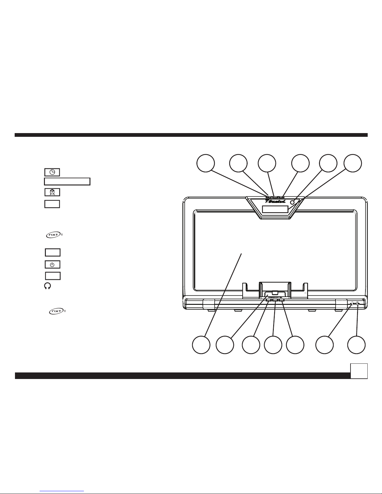
UNPACKING AND SETTING UP YOUR SOLOIST

Desktop Docking Station
© Directed Electronics, all rights reserved. 9
Soloist Universal Sound System
H
G
F
E
D
C
B
A
31 2 54 876
H
G
F
E
11109 1312
D
C
B
15 1614
A
31 2 54 876 11109 1312 15 1614
123-0000-00
DWG. NO.
REV.
XA
SCALE:
1:1
UNIT:
MM
DESIGN: DATE:
HF 00-00-06
PDM:
00-00-06
DATE:
PCM:
00-00-06
DATE:
SHEET: 1 OF 1
FILE NAME:
PROJECT NO:
123-0000-00.SLDASM
474A
PROPRIETARY INFORMATION
STATEMENT
THIS DOCUMENT CONTAINS
CONFIDENTIAL AND PROPRIETARY
INFORMATION OF DIRECTED
ELECTRONICS INC, AND MAY NOT
BE DISCLOSED TO OTHERS,
REPRODUCED,OR USED WITHOUT
WRITTEN CONSENT FROM
DIRECTED ELECTRONICS INC.
Electronics, Inc.
0. : ±0.3
0.0 : ±0.2
0.00 : ±0.10
A° : ±1/2°
TOLERANCE
FINISH:
MATERIAL:
ABS
MT-11020
FRONT, HOUSING
TITLE:
REV DESCRIPTION DATE APPROVED
SIZE
A1
APPROVED DATE:
APPROVED BY:
HF
00-00-06
910 11 12 13
7 8
1 2 3 4 5 6
1 2 3 4 5
Soloist - Front View
1
LINE
AUX
SNOOZE
SLEEP
POWER
SOURCE
MUTE TIMER
MENU
PROG/
CLOCK
+
_
ON
OFF
Music Timer Button
2SNOOZE Snooze/Clock Set Button
3
LINE
AUX
SNOOZE
SLEEP
POWER
SOURCE
MUTE TIMER
MENU
PROG/
CLOCK
+
_
ON
OFF
Alarm Clock Button
4
LINE
AUX
SNOOZE
SLEEP
POWER
SOURCE
MUTE TIMER
MENU
PROG/
CLOCK
+
_
ON
OFF
Sleep Timer Button
5 IR sensor
6 Liquid Crystal Display
7 panel
8 Docking Cradle
9
LINE
AUX
SNOOZE
SLEEP
POWER
SOURCE
MUTE TIMER
MENU
PROG/
CLOCK
+
_
ON
OFF
Volume Down Button
10
LINE
AUX
SNOOZE
SLEEP
POWER
SOURCE
MUTE TIMER
MENU
PROG/
CLOCK
+
_
ON
OFF
Power/Source Button
11
LINE
AUX
SNOOZE
SLEEP
POWER
SOURCE
MUTE TIMER
MENU
PROG/
CLOCK
+
_
ON
OFF
Volume Up Button
12 Headphone Output Jack
13 AUX Auxiliary Input Jack
NOTE: The panel is rugged, but can be damaged
if punctured or pushed too hard. If anything is touching
the panel while playing the sound can be noisy and/or
distorted.

© Directed Electronics, all rights reserved.
10
H
G
F
E
D
C
B
A
31 2 54 876
H
G
F
E
11109 1312
D
C
B
15 1614
A
31 2 54 876 11109 1312 15 1614
123-0000-00
DWG. NO.
REV.
XA
SCALE:
1:1
UNIT:
MM
DESIGN: DATE:
HF 00-00-06
PDM:
00-00-06
DATE:
PCM:
00-00-06
DATE:
SHEET: 1 OF 1
FILE NAME:
PROJECT NO:
123-0000-00.SLDASM
474A
PROPRIETARY INFORMATION
STATEMENT
THIS DOCUMENT CONTAINS
CONFIDENTIAL AND PROPRIETARY
INFORMATION OF DIRECTED
ELECTRONICS INC, AND MAY NOT
BE DISCLOSED TO OTHERS,
REPRODUCED,OR USED WITHOUT
WRITTEN CONSENT FROM
DIRECTED ELECTRONICS INC.
Electronics, Inc.
0. : ±0.3
0.0 : ±0.2
0.00 : ±0.10
A° : ±1/2°
TOLERANCE
FINISH:
MATERIAL:
ABS
MT-11020
FRONT, HOUSING
TITLE:
REV DESCRIPTION DATE APPROVED
SIZE
A1
APPROVED DATE:
APPROVED BY:
HF
00-00-06
910 11 12 13
7 8
1 2 3 4 5 6
1 2 3 4 5
Soloist - Rear View
1 Line Input Jack
2 Line Out Jack
3 DC 12V Input Jack
4 Sirius Antenna Jack
5 MINI USB Connector

Desktop Docking Station
© Directed Electronics, all rights reserved. 11
Soloist Universal Sound System
Remote Control
32:(5
6285&( 087(
92/ 92/
(4 '%% 7,0(5
781(
0(18
&+
&+&$7
&$7
6(/(&70(025<
%$1'
-803
352*
&/2&.
POWER/SOURCE - Turns the system On/Off and selects music source.
MUTE - Mutes the sound of Soloist.
VOL - Increases the volume level of Soloist and provides increment adjustment of
Soloist’s clock, alarm and timers.
VOL - Decreases the volume level of Soloist and provides decrement adjustment of
Soloist’s clock, alarm and timers.
EQ - Selects the equalization mode.
DBB - Dynamic Bass Boost.
PROG/CLOCK - Sets the clock as described on page 15.
Also sets the display option as described on page 20.
TIMER - Configures the Music Timer and turns it on and off as describe on page 26.
- Selects the previous track or fast reverses the selection.
- Plays and pauses the track.
- Selects the next track or fast forwards the selection.
TUNE - Sirius radio Direct Tune function.
MENU - Sirius radio Menu selection.
- Sirius Favorites (Stiletto 100) or Record (Stiletto 10).
CH & CH - Navigates through channels and display screens on Sirius radios.
BAND - Switches between preset bands on Sirius radios.
MEMORY - Sirius radio Memory function.
SELECT - Selects items highlighted on the Sirius display screen.
JUMP - Sirius radio Jump function.
CAT or - Navigates through categories on Sirius radios.
Numbers 0-9 - Used to select channels or presets on Sirius radios.

© Directed Electronics, all rights reserved.
12
Docking Cradle Types
Stiletto 2 Sportster 3/4
iPod
Adapter for Starmate/Stratus 3, 4 and Sportster 5
Two sided adhesive tape is provided to
permanently attach this adaptor to the
Sportster 4 docking cradle.
Adjustable back stop for
different iPod models.
Stiletto 10/1OO

Desktop Docking Station
© Directed Electronics, all rights reserved. 13
Soloist Universal Sound System
DETAIL A
SCALE 1 : 1
<COMPANY NAME>
SCALE:1:2
SIZE DWG. NO.
A
REV.
MATERIAL
FINISH
--
--
DO NOT SCALE DRAWING
APPLICATION
USED ON
NEXT ASSY
DIMENSIONS ARE IN INCHES
TOLERANCES:
FRACTIONAL ±
ANGULAR: MACH ± BEND ±
TWO PLACE DECIMAL ±
THREE PLACE DECIMAL ±
NAME DATE
DRAWN
CHECKED
ENG APPR.
MFG APPR.
Q.A.
SHEET 1 OF 1
WEIGHT:
COMMENTS:
THE INFORMATION CONTAINED IN THIS
DRAWING IS THE SOLE PROPERTY OF
<INSERT COMPANY NAME HERE>. ANY
REPRODUCTION IN PART OR AS A WHOLE
WITHOUT THE WRITTEN PERMISSION OF
<INSERT COMPANY NAME HERE> IS
PROHIBITED.
PROPRIETARY AND CONFIDENTIAL
A
Top View
+
Soloist comes with the Sirius
connector secured to the left
with a screw
Connector sides from left to
right depending on cradle being
used
Front If connector is positioned to
the right, insert screw here
Before Inserting the Stiletto Cradles
The Sirius connector can be moved to the left or right to
match up with the Sirius radio being docked. Soloist comes
setup for Sirius plug and play radios. If you plan to use a
Stiletto portable radio, the connector needs to be moved to
the right before inserting the cradle.
Remove the securing screw on the left of the connector and
slide the connector to the right. Secure the connector by
reinserting the screw in the hole on the right of the connec-
tor as shown.

© Directed Electronics, all rights reserved.
14
Inserting Docking Cradle
Before docking your music player, the proper cradle must
be installed in Soloist.
Make sure the docking cradle fits over the connectors.
Insert the two front tabs and then snap in at rear. The
provided screw can be inserted to secure the Sirius cradles
if desired.
If installing a Sirius docking cradle, make sure the connec-
tor is moved to the correct position as described on page
13.
<COMPANY NAME>
SCALE:1:2
SIZE DWG. NO.
A
REV.
MATERIAL
FINISH
--
--
DO NOT SCALE DRAWING
APPLICATION
USED ON
NEXT ASSY
DIMENSIONS ARE IN INCHES
TOLERANCES:
FRACTIONAL ±
ANGULAR: MACH ± BEND ±
TWO PLACE DECIMAL ±
THREE PLACE DECIMAL ±
NAME DATE
DRAWN
CHECKED
ENG APPR.
MFG APPR.
Q.A.
SHEET 1 OF 1
WEIGHT:
COMMENTS:
THE INFORMATION CONTAINED INTHIS
DRAWING IS THE SOLE PROPERTY OF
<INSERT COMPANY NAME HERE>. ANY
REPRODUCTION IN PART OR AS AWHOLE
WITHOUT THE WRITTEN PERMISSION OF
<INSERT COMPANY NAME HERE> IS
PROHIBITED.
PROPRIETARY AND CONFIDENTIAL
<COMPANY NAME>
SCALE:1:2
SIZE DWG. NO.
A
REV.
MATERIAL
FINISH
--
--
DO NOT SCALE DRAWING
APPLICATION
USED ON
NEXT ASSY
DIMENSIONS ARE IN INCHES
TOLERANCES:
FRACTIONAL ±
ANGULAR: MACH ± BEND ±
TWO PLACE DECIMAL ±
THREE PLACE DECIMAL ±
NAME DATE
DRAWN
CHECKED
ENG APPR.
MFG APPR.
Q.A.
SHEET 1 OF 1
WEIGHT:
COMMENTS:
THE INFORMATION CONTAINED IN THIS
DRAWING IS THE SOLE PROPERTY OF
<INSERT COMPANY NAME HERE>. ANY
REPRODUCTION IN PART OR AS A WHOLE
WITHOUT THE WRITTEN PERMISSION OF
<INSERT COMPANY NAME HERE> IS
PROHIBITED.
PROPRIETARY AND CONFIDENTIAL
Side view
Phillips Screw Driver
Screw
(optional)
Docking Cradle
(snaps in at rear)
Soloist

Desktop Docking Station
© Directed Electronics, all rights reserved. 15
Soloist Universal Sound System
Press
LINE
AUX
SNOOZE
SLEEP
POWER
SOURCE
MUTE TIMER
MENU
PROG/
CLOCK
+
_
ON
OFF
or
LINE
AUX
SNOOZE
SLEEP
POWER
SOURCE
MUTE TIMER
MENU
PROG/
CLOCK
+
_
ON
OFF
again and the hours digits
of the clock will flash.
Press
LINE
AUX
SNOOZE
SLEEP
POWER
SOURCE
MUTE TIMER
MENU
PROG/
CLOCK
+
_
ON
OFF
or
LINE
AUX
SNOOZE
SLEEP
POWER
SOURCE
MUTE TIMER
MENU
PROG/
CLOCK
+
_
ON
OFF
to set the hour. AM and PM is
selected in 12 hour mode by advancing the hour until the
AM or PM is properly displayed.
Press
LINE
AUX
SNOOZE
SLEEP
POWER
SOURCE
MUTE TIMER
MENU
PROG/
CLOCK
+
_
ON
OFF
or
LINE
AUX
SNOOZE
SLEEP
POWER
SOURCE
MUTE TIMER
MENU
PROG/
CLOCK
+
_
ON
OFF
again and the minutes
digits of the clock will flash.
Press
LINE
AUX
SNOOZE
SLEEP
POWER
SOURCE
MUTE TIMER
MENU
PROG/
CLOCK
+
_
ON
OFF
or
LINE
AUX
SNOOZE
SLEEP
POWER
SOURCE
MUTE TIMER
MENU
PROG/
CLOCK
+
_
ON
OFF
to set the minutes.
Setting the clock
The clock can only be set when Soloist is off. When the
system is powered up for the first time, the display will
flash to indicate the clock is not set.
To enter the clock set routine:
Press
LINE
AUX
SNOOZE
SLEEP
POWER
SOURCE
MUTE TIMER
MENU
PROG/
CLOCK
+
_
ON
OFF
or
LINE
AUX
SNOOZE
SLEEP
POWER
SOURCE
MUTE TIMER
MENU
PROG/
CLOCK
+
_
ON
OFF
for 3 seconds.
The Clock Set mode is activated and “12” will flash.
Press
LINE
AUX
SNOOZE
SLEEP
POWER
SOURCE
MUTE TIMER
MENU
PROG/
CLOCK
+
_
ON
OFF
or
LINE
AUX
SNOOZE
SLEEP
POWER
SOURCE
MUTE TIMER
MENU
PROG/
CLOCK
+
_
ON
OFF
to select “12 HOUR” or “24
HOUR” mode

© Directed Electronics, all rights reserved.
16
Press
LINE
AUX
SNOOZE
SLEEP
POWER
SOURCE
MUTE TIMER
MENU
PROG/
CLOCK
+
_
ON
OFF
or
LINE
AUX
SNOOZE
SLEEP
POWER
SOURCE
MUTE TIMER
MENU
PROG/
CLOCK
+
_
ON
OFF
again and the clock is set.
The colon will flash to indicate the clock is running.
LCD Contrast Setting
The LCD contrast can only be set when Soloist is off.
Press and hold
LINE
AUX
SNOOZE
SLEEP
POWER
SOURCE
MUTE TIMER
MENU
PROG/
CLOCK
+
_
ON
OFF
for 3 seconds and Soloist will
enter into LCD contrast setting,
Press
LINE
AUX
SNOOZE
SLEEP
POWER
SOURCE
MUTE TIMER
MENU
PROG/
CLOCK
+
_
ON
OFF
or
LINE
AUX
SNOOZE
SLEEP
POWER
SOURCE
MUTE TIMER
MENU
PROG/
CLOCK
+
_
ON
OFF
to set the LCD contrast level.
5 different contrast levels are selectable.

Desktop Docking Station
© Directed Electronics, all rights reserved. 17
Soloist Universal Sound System
Installing the Windowsill Antenna
Before installing the windowsill antenna, read this entire
section.
To ensure strong reception of the SIRIUS signal in your
home, it is important that the windowsill antenna be
oriented correctly. Note the following antenna placement
considerations:
BEST reception can be achieved by placing the antenna
outside on the roof. The antenna is waterproof. This posi-
tion will afford the best view of the sky for best reception.
When placed in this location, an antenna extension cable
may be required.
BETTER reception can be achieved by placing the antenna
outside a window, or by mounting it to the side of the
house. In either case, try to achieve the best possible clear
view of the sky.
GOOD reception can be achieved by placing your antenna
in a window. Try to achieve a clear unobstructed view of the
sky. If your location is in major metropolitan area, the an-
tenna may be located inside the home because terrestrial
transmitters are used to boost signal strength.
From the map shown here, determine your location and
aim the portion of the antenna with the logo toward the
location indicated by the X on the map.
Key:
Area 1: Aim the antenna East, Northeast, or Southeast
1
23
4
5
Area 2: Aim the antenna North or Northeast
Area 3: Aim the antenna North or Northwest
Area 4: Aim the antenna West, Northwest or Southwest
Area 5: Aim the antenna Straight Up at the sky
Route the antenna cable to the dock. Be sure you avoid
any obstructions that could crimp, kink, or twist the cable.
Use protective grommets wherever rough openings are
encountered. If the antenna is installed outdoors, route the
cable from the antenna location to the interior of the home,
working the cable through the basement, under a window
sill, etc., and make adjustments to take up cable slack as
necessary.
Connect the antenna cable to the ANT connection on the
rear of the dock.

© Directed Electronics, all rights reserved.
18
USING YOUR SOLOIST
Switching Soloist on and off
Press
LINE
AUX
SNOOZE
SLEEP
POWER
SOURCE
MUTE TIMER
MENU
PROG/
CLOCK
+
_
ON
OFF
or
LINE
AUX
SNOOZE
SLEEP
POWER
SOURCE
MUTE TIMER
MENU
PROG/
CLOCK
+
_
ON
OFF
to turn Soloist on. The LCD will
display "HELLO".
After 2 seconds, the LCD will display the current source.
Press and hold
LINE
AUX
SNOOZE
SLEEP
POWER
SOURCE
MUTE TIMER
MENU
PROG/
CLOCK
+
_
ON
OFF
or
LINE
AUX
SNOOZE
SLEEP
POWER
SOURCE
MUTE TIMER
MENU
PROG/
CLOCK
+
_
ON
OFF
for three 3 seconds to
turn Soloist off. The LCD will display "GOOD BYE"
The LCD backlight remains on for one minute. The
LCD backlight will turn on any time a button is pressed
and back off again one minute after the last button is
pressed.
Selecting a Source
Press
LINE
AUX
SNOOZE
SLEEP
POWER
SOURCE
MUTE TIMER
MENU
PROG/
CLOCK
+
_
ON
OFF
or
LINE
AUX
SNOOZE
SLEEP
POWER
SOURCE
MUTE TIMER
MENU
PROG/
CLOCK
+
_
ON
OFF
to select the desired source. The
LCD will display the selected source. Soloist remembers
the selected source when switched off and automatically
returns to that source when switched on again.

Desktop Docking Station
© Directed Electronics, all rights reserved. 19
Soloist Universal Sound System
Volume Control
Press
LINE
AUX
SNOOZE
SLEEP
POWER
SOURCE
MUTE TIMER
MENU
PROG/
CLOCK
+
_
ON
OFF
or
LINE
AUX
SNOOZE
SLEEP
POWER
SOURCE
MUTE TIMER
MENU
PROG/
CLOCK
+
_
ON
OFF
to adjust the volume on Soloist.
The volume level can be set from 00 to 30. Soloist
remembers the volume level when switched off and
automatically returns to same level when switched on
again.
Equalization Settings
Five equalization settings can be set by pressing EQ
The available settings are Flat (equalization off), Clas-
sic, Rock, Pop and Jazz. The LCD displays the selected
equalization setting.
Soloist remembers the equalization setting when
switched off and automatically returns to same setting
when switched on again.
Dynamic Bass Boost (DBB)
DBB is a bass enhancement system that improves the
low frequency response of Soloist.
Press DBB to toggle DBB on and off. The LCD will
indicate the status.
Soloist remembers the DBB setting when switched
off and automatically returns to same setting when
switched on again.

© Directed Electronics, all rights reserved.
20
Mute
Press
LINE
AUX
SNOOZE
SLEEP
POWER
SOURCE
MUTE TIMER
MENU
PROG/
CLOCK
+
_
ON
OFF
to toggle Mute on and off. The LCD will
indicate the status.
Display Option
When listening to music, Soloist can display the selected
source or the clock on the LCD.
Press
LINE
AUX
SNOOZE
SLEEP
POWER
SOURCE
MUTE TIMER
MENU
PROG/
CLOCK
+
_
ON
OFF
to switch between the current source and
the clock.
Using the Headphone Jack
The Headphone jack can be used with any pair of
headphones with the appropriate 3.5mm (1/8”) stereo
mini jack.
The audio output of Soloist is muted if headphones are
plugged into the headphone jack. When unplugging the
headphones, the volume is automatically reset to level
15 to avoid loud bursts of sound.
This manual suits for next models
1
Table of contents