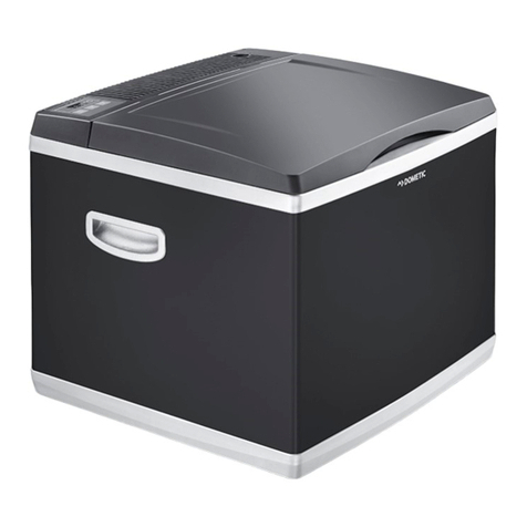
Distri Parts Glacier Original operating manual

SERVICE INSTRUCTION
COLD
Freezer
GLACIER
Publication number
599 52 72-98/5
Rev 07-02-22
SV/SERVICE
DA/MA/AN
©DISTRIPARTS AB
BOX 501
S-562 22 NORRAHAMMAR
Phone 036-31 80 00
Telefax 036-31 81 10
Telefax 036-31 80 88
B

2
SERVICE INSTRUCTION
Table of contents:
1. General
2. The glacier panel functions
3. Glacier function descriptions
3.1 Factory test
3.2 Icemaker on & off
3.3 Ice making
3.4 Ice dispensing
3.5 Locked mode
3.6 Lighting
3.7 Night mode
3.8 Anti condensation
4. Fault modes
4.1 General
4.2 Leaking water connection
4.3 No supply water
4.4 External ice gate not closed
4.5 Faulty NTC wiring
4.6 Faulty heater
4.7 Fault detection
5. Disassembly methodology
5.1 General
5.2 Door dispenser
5.3 Ice bin
5.4 Icemaker shelf
5.5 Upper air channel cover
5.6 Water connection box
5.7 Controller PCB in top panel

3
1.General
Glacier is an icemaker feature developed for use within 180 cm standard insulated
frost-free freezer appliances manufactured in Mariestad. The system basically consists
of a solenoid operated main valve distributing controlled amounts of water via plastic
hose and through a filling tube into the cooled cavity. The water is collected in an ice
tray, where the actual ice making takes place. Said tray is a part of the icemaker unit
which also consists of the motor and gearbox with internal hall-sensor, the NTC-probe
for detecting ice/water temperature inside ice tray and finally the chassis holding the
icemaker components together. The chassis also serves as interface to the
suspension shelf above. When every ice making cycle is complete the motor unit
twists the ice tray and its contents is released into the ice bin beneath. The ice bin
serves as a storage place for ice and constitutes the outer part of the auger system
which has the task to propel ice forward and out through the lid system located in the
door. The door dispenser is the user interface from where the dispensing of ice is
operated and controlled. All functions in the door panel along with the functions inside
and behind the appliance are supervised and controlled by the power PCB located
underneath the top panel.
2.The Glacier panel functions
b c d e
a) Switch (off / on) press and hold the alarm button (located in the top panel)
b) Locked mode indicator / fault code indicator
c) Key for temporary operation
d) Night mode key/Toggle lighting
e) Photo sensor window (night mode)
3.Glacier function description
3.1 Factory test
At first start up or at any occasion when the appliance is powered and the NTC sensor
of the twisting set, below referred to as the “NTC sensor”, detects a temperature
higher than 15 °C, a start up sequence operating all functions in parallel except the
main inlet valve is performed. The test finishes off with continuous lighting of the white
LEDs dimmed 50 % and the dispenser going into locked mode.
3.2 Icemaker on & off
The ice making function can be shut off by pressing and holding (default holding time ≥
one (1) second) alarm reset button in the appliance control panel The pressing is also
accompanied by two beeps. The default mode is however ON. When the icemaker
function is switched back on, it is recognised by the white lighting LEDs are being lit at
50% power. The system is restarted in the way it was shut off, i.e. direct dispensing
mode or locked mode active.

4
3.3 Ice making
After putting the appliance into operation and connecting it to a tap water supply, the
ice making system is ready for operation. The ice making cycle starts with the NTC
sensor detecting the temperature. If the temperature is below -9 °C the ice tray is
twisted twice than the level detecting lever is actuated. If no ice cubes prevents the
lever to complete its movement the solenoid valve is opened for 25 seconds in order to
fill the ice tray. The temperature increase in the ice tray is detected by the NTC sensor.
If for some reason the temperature rise doesn’t occur, the system immediately shuts
down triggering a fault signal on the dispenser unit in the door; refer subsection “Fault
modes”.
When, after proper filling of the ice tray, the NTC sensor detects a temperature lower
than or equal to -9 °C the ice tray is twisted and its contents are released into the ice
bin. The twisting motion is conducted twice On the return movement the ice level
detection lever makes its movement and if nothings interferes with the motion the ice
making cycle starts over. If however the movement is obstructed, the ice making cycle
is terminated. Once an hour the twisting set moves, in order to perform ice level
detection. If, during this operation, the movement is completed the ice making cycle
restarts.
If the wiring to the ice maker is damaged or not properly assembled causing the power
PCB to detect an infinite resistance from the NTC, the icemaker shall shut off and a
fault signal on the door dispenser shall be triggered; refer subsection “Fault modes”.
If the cabinet door is opened during activity of icemaker in progress this activity shall
be completed. Exception: If the first of the two initial twisting motions of the ice tray is
going on the ice tray shall return to neutral position after only fulfilling the first twisting.
Moving scheme shall be regained after the door is closed assuming that the detected
of the ice tray is still lower than –9 °C.
Refer also appendix 1.
3.4 Ice dispensing
Ice dispensing is performed by pressing a vessel suitable for collecting ice against the
paddle situated in the door dispenser. If locked mode is active refer subsection 8 on
how to unlock system prior to use. By doing so, a lever and lid system in the door is
moved and opened. Hereby an opto coupler is activated which initiates the ice gate
actuator to open the ice bin lid. After a delay of 1 second related to the opening of the
ice bin lid, the auger system starts propelling the contents of the ice bin towards and
through the impeller located in the frontal part and ice cubes subsequently fall down
through the ice bin lid and the ice chute in the door. During ice dispensing the auger
moves forward for 10 seconds at 50% duty cycle and then the motor makes a reverse
movement for 95° + 55° followed by a forward movement of 95° (below referred to as
the idle motion) .Hereafter the forward motion starts again. This is done to prevent
jamming during dispensing. When removing the ice collecting vessel from the paddle,
the idle motion once again is performed. Hereafter the auger stops. The ice bin lid
closes immediately.
If the lid and lever system in the door for some reason has not fully made its return
movement, a second opto coupler on the dispenser PCB will trigger fault signal on the
door dispenser; refer subsection “Fault modes”.

5
3.5 Locked mode
The locked mode shall be the default mode during which the dispenser panel and
paddle is functionally blocked. The locked mode state is temporary bypassed by
pressing and holding the left hand button. The bypass is acknowledged by the yellow
LED going out. The locked mode becomes automatically active 10 seconds after the
last interaction with the dispenser. The locked mode can be disabled/enabled by
pressing and holding both buttons simultaneously. Further this change of mode is
acknowledged by the backlight of the left hand button lighting up.
3.6 Lighting
Lighting (white LEDs on the user interface PCB) is activated when either of the buttons
or the ice dispensing paddle is pressed. The light is on as long as ice is dispensed plus
a timed delay of three (3) seconds after dispensing action is finished. The light shall
dim up and down within one (1) second.
If any key is pressed and no further action is taking place the LEDs will go out after ten
seconds.
Lighting can be switched on by pressing and holding the right button, assuming that
the locked mode is either bypassed or disabled. After the above-described sequences,
the light will dim down to a level corresponding to 50 % of maximum power.
3.7 Night mode
The night mode function is used to terminate the ice making and anti clumping function
during the darker period of the day. The function is facilitated by the use of a
photoelectric sensor located in the right hand corner of the user interface panel in the
door. This feature is activated/ deactivated by pressing and releasing the right button,
assuming that the locked mode is either bypassed or disabled. Change of state is
acknowledged by the backlight of the right hand button lighting up. If there is a need to
dispense ice when this night mode is in operation it will be possible to do so assuming
that there is ice available. When this function is in operation and in order to make an
accurate detection of light conditions, all LEDs shut down for 100 ms. Light conditions
is checked once every hour and whenever a system action is required.
3.8 Anti condensation
This function is always on during the use of the icemaker. A separate wiring btw the
power PCB and the dispenser PCB supplies the 3 W heater element located in the
insert bay. The heater is working in parallel with the icemaker function.
4 Fault modes
4.1General
If a, by the system detectable, fault occurs the white light in the dispenser will flash on
and off. The user has the possibility to reset the alarm by, in this instant, pressing any
button (this shall be possible even if the dispenser is in locked mode). The flashing
light will then go off but the left hand LED will continue to blink until remedial action
has been taken.
The following fault modes can be detected by the system;
4.2 Leaking water connection
Leakage in the connection box due to poor installation of the appliance, i.e. if the nut of
the connection hose is not sufficiently torqued causing a small leak. Further, if the
remote event of a leaky valve occurs the fault is also indicated. Reset is made by

6
draining the connection box from water. Alarm state shall become active as soon as
detected. This fault is indicated by a single blink by the yellow LED every 2 seconds
4.3 No supply water
If water filling of the ice tray is not detected. Reset is made by pressing and holding
(for more than one second) the paddle in the dispenser. In this mode the only action
resulting is the reset of the alarm, no dispensing will occur. Alarm state shall become
active as soon as detected. This fault is indicated by a double blink by the yellow LED
every 2 seconds
4.4 External ice gate not closed
If the lid in the dispenser is not fully closed. Reset is made by making sure that the lid
in the door is closed. Alarm state shall become active 30 seconds after detection. This
fault is indicated by a triple blink by the yellow LED every 2 seconds
4.5 Faulty ice maker wiring
If the wiring to the ice maker is damaged or not properly assembled causing the power
PCB to detect an infinite resistance from the NTC, the icemaker shall shut off and a
fault signal on the door dispenser shall be triggered. Alarm state shall become active
immediately after the triggering. This fault is indicated by a quadruple blink by the
yellow LED every 2 seconds.
4.6 Faulty heater
If the heater is broken or if its supply voltage for some reason is gone a fault signal is
triggered. This fault is indicated by five consecutive blinks every two seconds.
4.7 Fault detection
If the dispenser lighting of the dispenser panel is blinking an no function related to the
pushbuttons of the panel the dispenser PCB is broken and needs replacement.
During function control of the system it is suitable to check whether the direction of
movement of the auger corresponds to the description above. If this is not case the
fault is likely to be found in the connection located behind the service lid in the upper
ventilation channel cover.
If the panel doesn´t respond to button operation and seem to be out of power after the
start up sequence, refer appropriate clause, the communication btw the appliance
controller PCB and the ice maker system controller PCB shall be checked. Refer
wiring diagramme.
Suspicion of faulty connection valve or obstructed filling tube can be checked
according to the following procedure. Disconnect the appliance from mains supply.
Release the condensor in order to access the filling tube. Remove the hose from the
filling tube. Connect the appliance to mains supply again and await the twisting cycle
of the ice maker (assuming the temperature within the appliance is below –9 °C).
Under normal conditions the valve shall open and dispense circa 0,1 liter. If not, the
valve or the controller PCB is broken and needs replacement. If everything so far is
OK a 6 mm hose shall be connected to the filling tube. Apply by blowing into the tube
an over pressure to determine whether an obstruction is present.
5 Disassembly methodology
5.1 General
During all interventions the appliance has to be disconnected from mains supply. It is
NOT sufficient to shut off the appliance using the breaker in the top panel.

7
5.2 Door dispenser
The dispenser is disassembled according to following methodology:
• Perforate the decor in its geometrical centre using a slot screwdriver with 5 mm
blade. Release the decor gently. Unscrew both screws attaching the panel to
the PCB holder. Insert a screwdriver in the slots located in lowest part of the
panel and turn the handle of screwdriver outwards. This causes the snap in
connections to release.
• Remove the tape covering the wiring and release the foil cable by gently moving
the brown locking device upwards. Disconnect the wiring of the heater. Unscrew
the three screws holding PCB holder to the insert bay and release the holder
from the door.
• Insert a screwdriver in the space btw the left joint of the paddle. Pry gently to
the left simultaneously with moving the paddle forward. Repeat the procedure
on the right side.
• Open the lid to maximum and pull the lid downwards and to the right.
Reassembly is made in the following manner:
• Begin reassembly of the lid by entering the right side first. Make sure that the
spring is mounted correctly.
• Open the lid and position the guide pins of the paddle in the side flanges of the
lid and push the paddle in position.
• Remount the PCB holder. Reinsert the foil cable with the blue side facing right.
Lock the cable connector and connect the heater. Fold the excess wiring and
secuer it with the tape.
• Remount a new panel and decor.
5.3 Ice bin
The front of the ice bin is disassembled in the following manner:
• Remove the ice bin from the appliance. Push the snap in connector upwards
and tilt the front outwards.
The front of the ice bin is remounted in reverse order.
5.4 Icemaker shelf
The shelf is disassembled according to methodology as described below:
• Remove the protection cover in front of the icemaker by inserting a slot
screwdriver in front of the snap in connection on the right side of the icemaker.
Pry gently to the right. Hold on to the cover using the free hand and pull
simultaneously outwards.
• Disconnect the wiring by pressing the small lever on the right side of the
connector to the left at the pull the connector outwards. Release the wire from
its mechanical relief.

8
• Unscrew the two screws underneath and back side of the shelf. Lift the shelf in
the back part and pull it outwards. Exercise caution concerning the wiring. Pay
attention to the routing of the icemaker wire if further disassembly is required.
• Dismount the icemaker by placing the shelf upside down on firm foundation.
Hold on to the frontal part of the plastic console and apply opposing force using
the thumbs on the frontal part of the shelf and push hard.
The shelf is remounted in the following way:
• Place the air guide the intended way and position the icemaker in front of its
four fixing points on the shelf. Push the icemaker in place.
• Route the wiring making sure that it does not go through the plastic console.
Push the shelf in position and make sure that the wiring is routed correctly and
fixed by its mechanical relieves. Connect the wire to the icemaker and remount
the cover. Attach finally the cover to the liner using the two screws.
5.5 Upper air channel cover.
The cover is dismounted in the following manner:
• Pull out the appliance from its installation. And release the fasteners of the
conderser in order to access the mutiple connectors on the back. Disconnect
the wiring and remove the plastic sealing matter covering the lead through hole
• Remove the ice bin, the icemaker shelf and other interior furnishing preventing
access.
• Turn the plastic fasteners 90 ° counter clockwise and remove them.
• Take hold of the edges of the cover at a point levelling the end of the filling tube.
Bend the cover and pull it outwards at the same time. When the cover is
released make sure that the wiring is not damaged.
The cover is remounted in reverse order.
5.6 Connection box.
The connection box is disassembled in the following manner:
• Close water supply and unscrew the connection hose.
• Compress the double snap in connection sideways and turn the box to the
left simultaneously. Release the single snap in connection and turn the box
to the right. Work finally the box in order to come lose from the frontal guide
hole.
• Insert a screwdriver in the clamps on the right side of the box respectively an
lift the lid.
• Press the red collet at the orifice of the valve and pull the hose outwards.

9
• Disconnect the wiring.
The connection box is remounted in reverse order with the amendment of recutting the
end of the hose according to what has been previously described.
5.7 Controller PCB in top panel
The controller PCB in the top panel is dismounted in the following way.
• Release the screws in the back of the top panel. Lift it up and secure it using
a suitable object.
• Release the paper tape and pull the PCB holder downwards. Release the
wire connectors. Exercise particular caution concerning releasing the foil
cable.
Reassemble in reverse order.

10
WAIT TEMP
Do: read ntc (ice tray sensor)
POWER ON
SEPARATE
Do: separate ice from tray
SEPARATE - RETURN
Do: return to horizontal pos.
Temp < -9°C
Ice maker timing chart
SURVEY
Do: ice surveying action
SURVEY - RETURN
Do: return to horizontal pos.
SURVEY-INTERVAL
Do: wait 1 hour
Ice detected
FILL
Do: fill ice tray with water
FILL-VERIFY
Do: check temp rise ntc sensor
No ice detected
ALARM STATE
Do: 2 blinks yellow LED
Tem
p
rise OK
Tem
p
rise not OK
Remed
y
+ Reset
Table of contents
