Ditch Witch ht25 User manual

HT25 - SERVICE 1
SERIAL NUMBER RECORD
HT25 - SERVICE 1
SERIAL NUMBER RECORD
SERVICE
SERIAL NUMBER RECORD
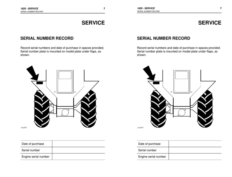
Record serial number and date of purchase in spaces provided.
Tractor serial number is located as shown.
Date of Manufacture:
Date of Purchase:
Tractor Serial Number:
Front Attachment Serial Number:
Engine Serial Number:
Trailer Serial Number:
SERVICE
SERIAL NUMBER RECORD
Record serial number and date of purchase in spaces provided.
Tractor serial number is located as shown.
Date of Manufacture:
Date of Purchase:
Tractor Serial Number:
Front Attachment Serial Number:
Engine Serial Number:
Trailer Serial Number:

2HT25 - SERVICE
SUPPORT PROCEDURE 2HT25 - SERVICE
SUPPORT PROCEDURE
SUPPORT PROCEDURE
Notify your dealer immediately of any malfunction or failure of
Ditch Witch equipment.
Always give model, serial number, and approximate date of
equipment purchase. This information should be recorded and
placed on file by owner at time of purchase.
Return damaged parts to dealer for inspection and Warranty
consideration.
Order genuine Ditch Witch replacement or repair parts from your
authorized Ditch Witch dealer. Use of another manufacturer's
parts may void warranty.
RESOURCES
Publications
Contact your Ditch Witch dealer for publications covering
operation, service, and repair of your equipment.
Ditch Witch Training
For information about on-site, individualized training, contact your
Ditch Witch dealer.

HT25 - FOREWORD 3
HT25 - FOREWORD 3
FOREWORD
This manual is an important part of your equipment. It provides
safety information and operation instructions to help you use and
maintain your Ditch Witch equipment.
Read this manual before using your equipment. Keep it with the
equipment at all times for future reference. If you sell your
equipment, be sure to give this manual to the new owner.
If you need a replacement copy, contact your Ditch Witch dealer.
If you need assistance in locating a dealer, visit our website at
www.ditchwitch.com or write to the following address:
The Charles Machine Works, Inc.
Attn: Marketing Department
PO Box 66
Perry, OK 73077-0066
USA
The descriptions and specifications in this manual are subject to
change. The Charles Machine Works, Inc. reserves the right to
improve equipment. Some product improvements may have taken
place after this manual was published. For the latest information
on Ditch Witch equipment, see your Ditch Witch dealer.
Thank you for buying and using Ditch Witch equipment.

4HT25 - FOREWORD 4HT25 - FOREWORD
Operator's Manual
Issue Number 1.0/OP-4/00
Part Number 054-062
Copyright 2000
by The Charles Machine Works, Inc.,
Perry, Oklahoma
, Ditch Witch, Jet Trac, Pro Tech, Fluid Miser, Perma-Soil,
Modularmatic, Roto Witch, AutoCrowd, and Subsite are
registered trademarks of The Charles Machine Works, Inc.
CMW is a trademark of The Charles Machine Works, Inc.
Pierce Airrow is a registered trademark of Oklahoma Airrow, Inc.

HT25 - CONTENTS 5
HT25 - CONTENTS 5
CONTENTS
SERVICE . . . . . . . . . . . . . . . . . . . . . . . . . . . . . . . . . . . . . . .1
Serial Number Record. . . . . . . . . . . . . . . . . . . . . . . . . .1
Support Procedure . . . . . . . . . . . . . . . . . . . . . . . . . . . .2
Resources. . . . . . . . . . . . . . . . . . . . . . . . . . . . . . . . . . .2
FOREWORD. . . . . . . . . . . . . . . . . . . . . . . . . . . . . . . . . . . . .3
OVERVIEW. . . . . . . . . . . . . . . . . . . . . . . . . . . . . . . . . . . . . .9
CONTROLS . . . . . . . . . . . . . . . . . . . . . . . . . . . . . . . . . . . .11
Overview . . . . . . . . . . . . . . . . . . . . . . . . . . . . . . . . . . .11
Descriptions. . . . . . . . . . . . . . . . . . . . . . . . . . . . . . . . .12
SAFETY . . . . . . . . . . . . . . . . . . . . . . . . . . . . . . . . . . . . . . .19
Accessories. . . . . . . . . . . . . . . . . . . . . . . . . . . . . . . . .20
Underground Hazards. . . . . . . . . . . . . . . . . . . . . . . . .20
Emergency Procedures. . . . . . . . . . . . . . . . . . . . . . . .21
Jobsite Classification. . . . . . . . . . . . . . . . . . . . . . . . . .24
Safety Alert Classifications . . . . . . . . . . . . . . . . . . . . .28
Safety Alerts . . . . . . . . . . . . . . . . . . . . . . . . . . . . . . . .29
CONTENTS
SERVICE . . . . . . . . . . . . . . . . . . . . . . . . . . . . . . . . . . . . . . . 1
Serial Number Record . . . . . . . . . . . . . . . . . . . . . . . . . 1
Support Procedure . . . . . . . . . . . . . . . . . . . . . . . . . . . . 2
Resources . . . . . . . . . . . . . . . . . . . . . . . . . . . . . . . . . . 2
FOREWORD . . . . . . . . . . . . . . . . . . . . . . . . . . . . . . . . . . . . 3
OVERVIEW . . . . . . . . . . . . . . . . . . . . . . . . . . . . . . . . . . . . . 9
CONTROLS. . . . . . . . . . . . . . . . . . . . . . . . . . . . . . . . . . . . 11
Overview. . . . . . . . . . . . . . . . . . . . . . . . . . . . . . . . . . . 11
Descriptions . . . . . . . . . . . . . . . . . . . . . . . . . . . . . . . . 12
SAFETY. . . . . . . . . . . . . . . . . . . . . . . . . . . . . . . . . . . . . . . 19
Accessories . . . . . . . . . . . . . . . . . . . . . . . . . . . . . . . . 20
Underground Hazards . . . . . . . . . . . . . . . . . . . . . . . . 20
Emergency Procedures . . . . . . . . . . . . . . . . . . . . . . . 21
Jobsite Classification . . . . . . . . . . . . . . . . . . . . . . . . . 24
Safety Alert Classifications. . . . . . . . . . . . . . . . . . . . . 28
Safety Alerts. . . . . . . . . . . . . . . . . . . . . . . . . . . . . . . . 29

6HT25 - CONTENTS 6HT25 - CONTENTS
TRACTOR . . . . . . . . . . . . . . . . . . . . . . . . . . . . . . . . . . . . . 35
Daily Inspection . . . . . . . . . . . . . . . . . . . . . . . . . . . . . 35
Startup . . . . . . . . . . . . . . . . . . . . . . . . . . . . . . . . . . . . 36
Operation . . . . . . . . . . . . . . . . . . . . . . . . . . . . . . . . . . 38
Shutdown . . . . . . . . . . . . . . . . . . . . . . . . . . . . . . . . . . 38
TRANSPORTATION . . . . . . . . . . . . . . . . . . . . . . . . . . . . . 39
Lift. . . . . . . . . . . . . . . . . . . . . . . . . . . . . . . . . . . . . . . . 39
Tiedown . . . . . . . . . . . . . . . . . . . . . . . . . . . . . . . . . . . 40
Haul . . . . . . . . . . . . . . . . . . . . . . . . . . . . . . . . . . . . . . 41
Tow. . . . . . . . . . . . . . . . . . . . . . . . . . . . . . . . . . . . . . . 44
TRENCHING . . . . . . . . . . . . . . . . . . . . . . . . . . . . . . . . . . . 45
Control Overview . . . . . . . . . . . . . . . . . . . . . . . . . . . . 45
Control Descriptions . . . . . . . . . . . . . . . . . . . . . . . . . . 46
Setup . . . . . . . . . . . . . . . . . . . . . . . . . . . . . . . . . . . . . 47
Operation . . . . . . . . . . . . . . . . . . . . . . . . . . . . . . . . . . 49
Operating Tips . . . . . . . . . . . . . . . . . . . . . . . . . . . . . . 51
Optional Equipment . . . . . . . . . . . . . . . . . . . . . . . . . . 51
BACKHOE . . . . . . . . . . . . . . . . . . . . . . . . . . . . . . . . . . . . . 53
Control Overview . . . . . . . . . . . . . . . . . . . . . . . . . . . . 53
Control Descriptions . . . . . . . . . . . . . . . . . . . . . . . . . . 54
Setup . . . . . . . . . . . . . . . . . . . . . . . . . . . . . . . . . . . . . 56
Operation . . . . . . . . . . . . . . . . . . . . . . . . . . . . . . . . . . 57
TRACTOR . . . . . . . . . . . . . . . . . . . . . . . . . . . . . . . . . . . . . 35
Daily Inspection . . . . . . . . . . . . . . . . . . . . . . . . . . . . . 35
Startup . . . . . . . . . . . . . . . . . . . . . . . . . . . . . . . . . . . . 36
Operation . . . . . . . . . . . . . . . . . . . . . . . . . . . . . . . . . . 38
Shutdown . . . . . . . . . . . . . . . . . . . . . . . . . . . . . . . . . . 38
TRANSPORTATION . . . . . . . . . . . . . . . . . . . . . . . . . . . . . 39
Lift . . . . . . . . . . . . . . . . . . . . . . . . . . . . . . . . . . . . . . . 39
Tiedown . . . . . . . . . . . . . . . . . . . . . . . . . . . . . . . . . . . 40
Haul . . . . . . . . . . . . . . . . . . . . . . . . . . . . . . . . . . . . . . 41
Tow . . . . . . . . . . . . . . . . . . . . . . . . . . . . . . . . . . . . . . 44
TRENCHING . . . . . . . . . . . . . . . . . . . . . . . . . . . . . . . . . . . 45
Control Overview . . . . . . . . . . . . . . . . . . . . . . . . . . . . 45
Control Descriptions. . . . . . . . . . . . . . . . . . . . . . . . . . 46
Setup . . . . . . . . . . . . . . . . . . . . . . . . . . . . . . . . . . . . . 47
Operation . . . . . . . . . . . . . . . . . . . . . . . . . . . . . . . . . . 49
Operating Tips . . . . . . . . . . . . . . . . . . . . . . . . . . . . . . 51
Optional Equipment . . . . . . . . . . . . . . . . . . . . . . . . . . 51
BACKHOE. . . . . . . . . . . . . . . . . . . . . . . . . . . . . . . . . . . . . 53
Control Overview . . . . . . . . . . . . . . . . . . . . . . . . . . . . 53
Control Descriptions. . . . . . . . . . . . . . . . . . . . . . . . . . 54
Setup . . . . . . . . . . . . . . . . . . . . . . . . . . . . . . . . . . . . . 56
Operation . . . . . . . . . . . . . . . . . . . . . . . . . . . . . . . . . . 57

HT25 - CONTENTS 7
HT25 - CONTENTS 7
LUBRICATION . . . . . . . . . . . . . . . . . . . . . . . . . . . . . . . . . .59
Overview . . . . . . . . . . . . . . . . . . . . . . . . . . . . . . . . . . .60
Schedule . . . . . . . . . . . . . . . . . . . . . . . . . . . . . . . . . . .61
Engine. . . . . . . . . . . . . . . . . . . . . . . . . . . . . . . . . . . . .62
Ground Drive. . . . . . . . . . . . . . . . . . . . . . . . . . . . . . . .64
Hydraulics . . . . . . . . . . . . . . . . . . . . . . . . . . . . . . . . . .66
Trencher . . . . . . . . . . . . . . . . . . . . . . . . . . . . . . . . . . .68
Backfill Blade. . . . . . . . . . . . . . . . . . . . . . . . . . . . . . . .71
MAINTENANCE . . . . . . . . . . . . . . . . . . . . . . . . . . . . . . . . .73
Overview . . . . . . . . . . . . . . . . . . . . . . . . . . . . . . . . . .74
Engine. . . . . . . . . . . . . . . . . . . . . . . . . . . . . . . . . . . . .75
Ground Drive. . . . . . . . . . . . . . . . . . . . . . . . . . . . . . . .80
Hydraulics . . . . . . . . . . . . . . . . . . . . . . . . . . . . . . . . . .83
Electrical . . . . . . . . . . . . . . . . . . . . . . . . . . . . . . . . . . .84
Trencher . . . . . . . . . . . . . . . . . . . . . . . . . . . . . . . . . . .85
SPECIFICATIONS . . . . . . . . . . . . . . . . . . . . . . . . . . . . . . .93
HT25 . . . . . . . . . . . . . . . . . . . . . . . . . . . . . . . . . . . . . .93
A225 Backhoe. . . . . . . . . . . . . . . . . . . . . . . . . . . . . . .97
LUBRICATION. . . . . . . . . . . . . . . . . . . . . . . . . . . . . . . . . . 59
Overview. . . . . . . . . . . . . . . . . . . . . . . . . . . . . . . . . . . 60
Schedule. . . . . . . . . . . . . . . . . . . . . . . . . . . . . . . . . . . 61
Engine . . . . . . . . . . . . . . . . . . . . . . . . . . . . . . . . . . . . 62
Ground Drive . . . . . . . . . . . . . . . . . . . . . . . . . . . . . . . 64
Hydraulics. . . . . . . . . . . . . . . . . . . . . . . . . . . . . . . . . . 66
Trencher. . . . . . . . . . . . . . . . . . . . . . . . . . . . . . . . . . . 68
Backfill Blade . . . . . . . . . . . . . . . . . . . . . . . . . . . . . . . 71
MAINTENANCE. . . . . . . . . . . . . . . . . . . . . . . . . . . . . . . . . 73
Overview . . . . . . . . . . . . . . . . . . . . . . . . . . . . . . . . . . 74
Engine . . . . . . . . . . . . . . . . . . . . . . . . . . . . . . . . . . . . 75
Ground Drive . . . . . . . . . . . . . . . . . . . . . . . . . . . . . . . 80
Hydraulics. . . . . . . . . . . . . . . . . . . . . . . . . . . . . . . . . . 83
Electrical. . . . . . . . . . . . . . . . . . . . . . . . . . . . . . . . . . . 84
Trencher. . . . . . . . . . . . . . . . . . . . . . . . . . . . . . . . . . . 85
SPECIFICATIONS. . . . . . . . . . . . . . . . . . . . . . . . . . . . . . . 93
HT25. . . . . . . . . . . . . . . . . . . . . . . . . . . . . . . . . . . . . . 93
A225 Backhoe . . . . . . . . . . . . . . . . . . . . . . . . . . . . . . 97

8HT25 - CONTENTS 8HT25 - CONTENTS

HT25 - OVERVIEW 9
HT25 - OVERVIEW 9
OVERVIEW
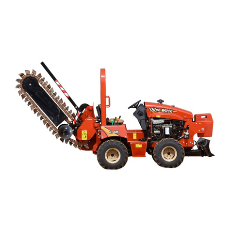
The HT25 is a 25 hp (18.6 kW) riding tractor that can be fitted
with a centerline, wide centerline, or offset digging boom.
Optional cab, backfill blade, backhoe, drilling attachment, and
mechanical trench cleaner are available. The HT25 is designed to
cut trenches up to 36 in (91 cm) deep and 16 in (40 cm) wide.
1. Digging boom
2. Lift/tiedown point
3. Engine compartment
4. Rollover Protective Structure
5. Operator’s position
6. Control console
7. Lift/tiedown point
8. Backfill blade*
*optional

10 HT25 - OVERVIEW 10 HT25 - OVERVIEW

HT25 - CONTROLS 11
OVERVIEW
HT25 - CONTROLS 11
OVERVIEW
CONTROLS
OVERVIEW
1. Throttle
2. Accessory socket*
3. Backfill blade control*
4. Dome light switch*
5. Windshield wiper switch*
6. Work light switch*
7. Track controls
8. Horn button
9. Digging chain control**
10. Glow plug control
11. Ignition switch
12. Fuel gauge
13. Start interlock indicators
14. Engine water temperature
indicator
15. Engine oil pressure indicator
16. Heater fan control*
17. Heater temperature control*
18. Boom lift control**
19. Battery disconnect*
20. Hourmeter
* Optional
**See TRENCHING for a description of
this control.

12 HT25 - CONTROLS
DESCRIPTIONS 12 HT25 - CONTROLS
DESCRIPTIONS
DESCRIPTIONS
Throttle
This lever controls engine speed.
•Push to increase speed.
•Pull to reduce speed.
Accessory Socket
This optional outlet can be used to
provide power for work lights or other
equipment.
ic0128h.eps
DESCRIPTIONS
Throttle
This lever controls engine speed.
•Push to increase speed.
•Pull to reduce speed.
Accessory Socket
This optional outlet can be used to
provide power for work lights or other
equipment.
ic0128h.eps

HT25 - CONTROLS 13
DESCRIPTIONS
HT25 - CONTROLS 13
DESCRIPTIONS
Backfill Blade Control
This optional lever raises, lowers,
and swings backfill blade.
•Push to lower blade.
•Pull to raise blade.
•Move right to swing blade
right.
•Move left to swing blade left.
Work Light Switch
This optional switch controls front
and rear work lights.
•Press right to turn on.
•Press left to turn off.
Dome Light Switch
This optional button controls interior dome light.
•Press top to turn on.
•Press bottom to turn off.

14 HT25 - CONTROLS
DESCRIPTIONS 14 HT25 - CONTROLS
DESCRIPTIONS
Windshield Wiper Switch
This optional switch controls
windshield wipers.
•Press right to turn on.
•Press left to turn off.
Track Controls
These levers, used together,
control left and right track speed
and direction.
•Push to go forward.
•Pull to go backward.
•Return to neutral to stop.
•Use together to steer.
Engine Oil Pressure Indicator
This indicator lights when oil
pressure is low. Light will come on
briefly when engine is started.
If light remains on:
•Turn off engine.
•Check oil level.
•Check for leaks before starting
engine.
Ic0225h.eps
Ic0227h.eps
ic1294.eps

HT25 - CONTROLS 15
DESCRIPTIONS
HT25 - CONTROLS 15
DESCRIPTIONS
Start Interlock Indicators
To start machine, these must be lit,
indicating the following conditions
have been met:
•Operator is in seat.
•Track controls are in neutral.
•Digging chain clutch is not
engaged.
Horn Button
Press button to sound horn.
ic0138x.eps
Start Interlock Indicators
To start machine, these must be lit,
indicating the following conditions
have been met:
•Operator is in seat.
•Track controls are in neutral.
•Digging chain clutch is not
engaged.
Horn Button
Press button to sound horn.
ic0138x.eps

16 HT25 - CONTROLS
DESCRIPTIONS 16 HT25 - CONTROLS
DESCRIPTIONS
Glow Plug Button
This button helps start cold engine.
To operate, first turn ignition switch to
first position.
•If ambient temperature is below
40°F (4°C), press and hold
button for 15 seconds.
•If ambient temperature is below
20°F (-7°C), press and hold
button for 30 seconds.
Release button, then turn ignition switch all the way clockwise.
Ignition Switch
This three-position switch starts or
stops engine.
•Insertkeyandturnclockwiseto
first position.
•Press glow plugbutton towarm
cold engine if necessary. See
instructions for glow plug
button.
•Turn switch all the way
clockwise.
•Release when engine starts. Key will return to first position.
•Turn counterclockwise to stop engine.
If engine does not start on first attempt, check that all interlock
requirements have been met, return switch to STOP position, and
try again.
ic0219h.eps
Glow Plug Button
This button helps start cold engine.
To operate, first turn ignition switch to
first position.
•If ambient temperature is below
40°F (4°C), press and hold
button for 15 seconds.
•If ambient temperature is below
20°F (-7°C), press and hold
button for 30 seconds.
Release button, then turn ignition switch all the way clockwise.
Ignition Switch
This three-position switch starts or
stops engine.
•Insertkeyandturnclockwiseto
first position.
•Press glowplugbuttontowarm
cold engine if necessary. See
instructions for glow plug
button.
•Turn switch all the way
clockwise.
•Release when engine starts. Key will return to first position.
•Turn counterclockwise to stop engine.
If engine does not start on first attempt, check that all interlock
requirements have been met, return switch to STOP position, and
try again.
ic0219h.eps

HT25 - CONTROLS 17
DESCRIPTIONS
HT25 - CONTROLS 17
DESCRIPTIONS
Fuel Gauge
This gauge indicates fuel level in
tank. Use only #2 diesel fuel.
Engine Temperature Indicator
This indicator lights if cooling
system water overheats.
•Turn off engine and let cool.
•Check cooling system fluid
level.
Heater Fan Control
This optional knob adjusts heater
fan speed.
•Turn clockwise for faster.
•Turn counterclockwise for
slower.
ic1274.eps

18 HT25 - CONTROLS
DESCRIPTIONS 18 HT25 - CONTROLS
DESCRIPTIONS
Heater Temperature Control
This optional knob adjusts heater
temperature.
•Turn clockwise for warmer.
•Turn counterclockwise for
cooler.
Hourmeter
This gauge, located under seat,
records engine operating time.
Use these times to schedule
lubrication and maintenance.
Battery Disconnect
Use this optional knob, located
under seat, to disconnect battery
when servicing unit or during long-
term storage.
•Turn clockwise to connect
battery power.
•Turn counterclockwise to
disconnect battery power.

HT25 - SAFETY 19
HT25 - SAFETY 19
SAFETY
Follow these guidelines before operating any jobsite equipment:
•Complete proper training and read operator’s manual before
using equipment.
•Contact One-Call (888-258-0808) and any utility companies
which do not subscribe to One-Call. Have all underground
pipes and cables located and marked before operating
equipment. If you damage a utility, contact utility company.
•Classify jobsite based on its hazards and use correct tools
and machinery, safety equipment, and work methods for
jobsite.
•Mark jobsite clearly and keep spectators away.
•Wear personal protective equipment.
•Review jobsite hazards, safety and emergency procedures,
and individual responsibilities with all personnel before work
begins. Safety videos are available from your Ditch Witch
dealer.
•Replace missing or damaged safety shields and safety signs.
•Use equipment carefully. Stop operation and investigate
anything that does not look or feel right.
•Do not operate unit where flammable gas is present.
•Contact your Ditch Witch dealer if you have any question
about operation, maintenance, or equipment use.

20 HT25 - SAFETY
ACCESSORIES 20 HT25 - SAFETY
ACCESSORIES
ACCESSORIES
Fire Extinguisher
If required, a fire extinguisher should be mounted near the power
unit but away from possible points of ignition. The fire
extinguisher should always be classified for both oil and electric
fires. It should meet legal and regulatory requirements.
Lighting Kit
If you need additional light, plug lighting kit into provided outlet.
Contact your Ditch Witch dealer for further information.
UNDERGROUND HAZARDS
Striking underground hazards can cause explosion, electrocution,
fire, and exposure to hazardous materials.
Hazards include:
•Electric lines
•Natural gas lines
•Fiber optic cables
•Water lines
•Sewer lines
•Pipes carrying other chemicals, liquids, or gases
•Storage tanks
Table of contents
Other Ditch Witch Tractor manuals
