Haybuster Balebuster 2564 User manual
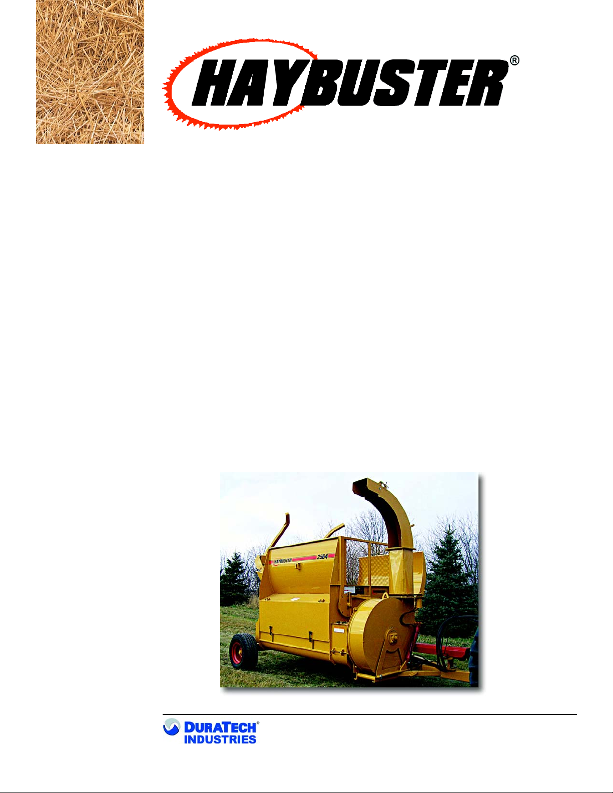
2564
BALEBUSTER
SERIAL NUMBERSERIAL NUMBER
SERIAL NUMBERSERIAL NUMBER
SERIAL NUMBER FJ053164FJ053164
FJ053164FJ053164
FJ053164 AND UPAND UP
AND UPAND UP
AND UP
OperOper
OperOper
Operaa
aa
ating Instrting Instr
ting Instrting Instr
ting Instructionsuctions
uctionsuctions
uctions
and Pand P
and Pand P
and Parar
arar
arts Rts R
ts Rts R
ts Refef
efef
eferer
erer
erenceence
enceence
ence
PO BOX 1940, JAMESTOWN, ND 58402-1940
APRIL 2008 0500128
TM
TM

A Tradition of Innovation Since 1966
TM
TM
OperOper
OperOper
Operaa
aa
ating Instrting Instr
ting Instrting Instr
ting Instructionsuctions
uctionsuctions
uctions
and Pand P
and Pand P
and Parar
arar
arts Rts R
ts Rts R
ts Refef
efef
eferer
erer
erenceence
enceence
ence
2564
BALEBUSTER
SERIAL NUMBER FJ053164 AND UP
DuraTech Industries International Inc.(DuraTech Industries) has made every effort to assure that
this manual completely and accurately describes the operation and maintenance of the 2564™
BALEBUSTER™ as of the date of publication. DuraTech Industries reserves the right to make
updates to the machine from time to time. Even in the event of such updates, you should still find
this manual to be appropriate for the safe operation and maintenance of your unit.
This manual, as well as materials provided by component suppliers to DuraTech Industries are all
considered to be part of the information package. Every operator is required to read and understand
these manuals, and they should be located within easy access for periodic review.
& are registered trademarks of Duratech Industries
International, Inc. 2564 and Balebuster are trademarks of Duratech Industries International, Inc.
STRAW CANNON®and logo are registered trademarks of Duratech Industries International, Inc.

A Tradition of Innovation Since 1966
i2564 BALEBUSTER OPERATING INSTRUCTIONS
FOREWORD
Foreword
All personnel must read and understand the following sections before operating the
BALEBUSTER™.
•Section 2, ”Dealer Preparation,” to verify that the machine has been prepared
for use.
•Section 3, “Operation,” which explain normal operation of the machine.
•Foreword and Section 1, important safety information.
•Section 3.1, “Pre-Operation Inspection”.
Appropriate use of unit
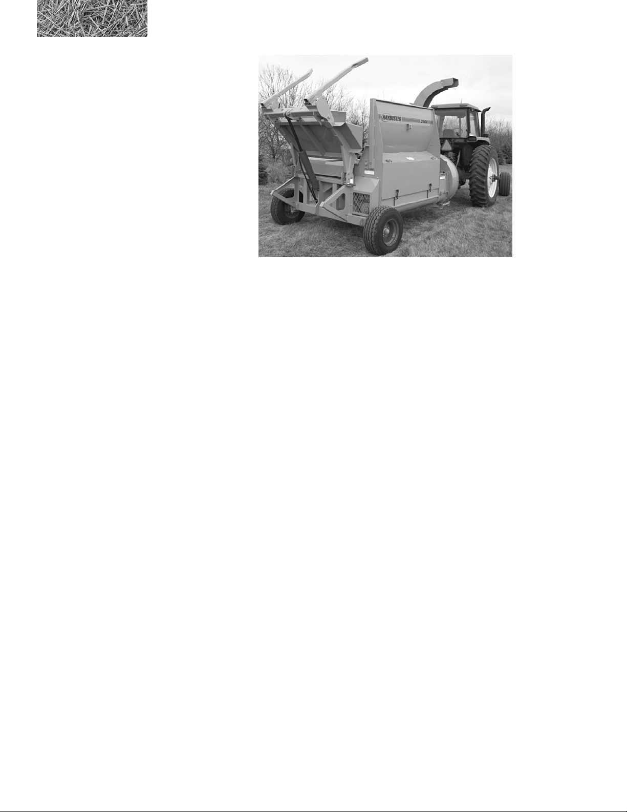
Your model 2564™ BALEBUSTER™ is designed to load and shred most types of
baled livestock forage. It is designed specifically for use on 6 foot. diameter round
bales weighing up to 2,000 pounds and 5-1/2 feet in length
To avoid possible damage to the machine and risk of injury to the operator, consult
with a DuraTech representative before attempting to shred materials other than
livestock forage.
The BALEBUSTER has multiple uses:
•Laying forage windrows in open fields.
•Filling feed bunks - fenceline, circular etc.
•Spreading straw for livestock bedding.
•Spreading mulch over perennial plants, such as strawberries, mushrooms, etc.
•Spreading mulch over reclaimed land areas.
•Spreading mulch over sugar beets for storage.
This manual suits for next models
1
Table of contents


