Ditchburn Music Maker 200 Quick start guide
Music Maker 200
T200 Service Engineers Manual
Also Suitable for
Tonomat Telematic 200 and MM200
This Manual is an English Translation of the Tonomat Telematic 200 Manual, many
thanks to Stuart and Sue Saunders for undertaking the translation and for the
assistance from Hildegard Stamann for the additional amendments, information and
use of diagrams within the manual.
Various parts and complete printed and bound original manuals for Ditchburn and
Tonomat Jukeboxes can be purchased from
www.jukebox-world.de/en/Onlineshop/
More information on Ditchburn Jukeboxes can be found at
www.ditchburn.co.uk

2
CONTENT
1. Important data of the "telematic 200"………………………………………………… 3
2. Installation and operation ……………………………………………………….. 4
3. Description of the electrical functions when dialing……………………………… 5
Coin…………………………………………………………………………………............ 5
Selection of the first digit……………………………………………………………………..5
Dial the second digit………………………………………………………………………. 5
Dial the third digit………………………………………………………………………….. 5
Raising the selector pin…………………………………………………………………… 5
Reset the rotary selector………………………………………………………….............. 6
4. Description of credit……..………………………………………………………….. 6
50 Pfg insert……………………………………………………………………………… 6
1 DM insert……………………………………………………………………………… 6
5. Change in the credit settings…………………………………………………………….. 7
6. Equipped with long-playing records………………………………………………….. 7
7. Electrical functions when selecting an LP…………………………………………… 8
Coin………………………………………………………………………………………….. 8
pay more appears……………………………………………………………………………. 8
The error button……………………………………………………………………………… 8
8. Description of the electrical functions when changing records…………………….9
Lifting a record………………………………………………………………………………… 9
Return the played disc……………………………………………………………………… 9
9. Adjustment regulation................................................................................................ 12
Lift and lower the records……………………………………………………………………..12
Center the record…………………………………………………………………................ 12
Adjustment of the switching cams………………………………………………................ 12/13
Raise and reset the selection pins…………………………………………………….. 14
Clean the sapphire………………………………………………………………………….. 14
10. Description of the mechanical functions when changing plates………………… 15
How the Record lifters work……………………………………………………………….. 15
Center the record…………………………………………………………………………… 15
Clutch pinion and turntable drive………………………………………………………….. 15
returns……………………………………………………………………………………….. 15
11. Diagnostic sources of interference......................................................................... 16
Troubles before dialing……………………………………………………………………. 16
after dialing………………………………………………………….............. 16
when changing……………………………………………………………… 17
while playing………………………………………………………………… 17
12. General electrical switching faults…………………………………………………….. 17
13. Maintenance and care……………………………………………………………………. 18
14. Guarantee……………………………………………………………………...................... 18
15. Individual parts of the mechanics……………………………………………………… 18 to 21
16. Individual parts - housing rear view…………………………………………………… 19
17. Single parts - housing front view………………………………………………………. 20

3
Important data
The "telematic 200"
Dimensions:
Height: 145 cm
Width: 94 cm
Depth: approx. 73 cm
Voltage values:
220 volt amplifier
Power Supply:
Input: 220 volts
Output: = 60 volts
Command Device
Control voltage of the relays: = 60 volts
Control voltage for motors 220 volts
Operating voltage for the player engine: 110 volts
(Half of the incoming voltage is destroyed by
the upstream resistor)
Service:
The records are selected using the dial disc
known from the telephone.
The request to choose and the '' wait '' sign
appears as a green or red illuminated
transparency to the right and left of the dial.
Another indicator lamp prompts you to “pay
extra '' when a long-playing record is selected.
The telephone system, which has been tried
and tested a million times, offers the choice of
up to 40 long-playing records with more than
200 options. An error button gives you the
option to undo an already initiated dialing.
Pickups:
Crystal system made by '' ELAC '' KST 11 with
Micro-sapphire SM11.
We advise you to replace the sapphire needle
after 2000 to 2500 games. On request, we can
also supply diamond needles with 30 times the
lifespan.
Amplifier:
30 Watt high-performance Hi-Fi amplifier with
connection option for additional speakers.
Tubes: 1 x EZ 81, 4 X EL 84, 2 X ECC 81.
A potentiometer serves as the volume control.
50 K-ohm layer resistance.
For more detailed information about the
amplifier, please refer to the separate
operating and service instructions enclosed
with the guarantee cards for the amplifier tubes.
Speaker:
Two permanently dynamic loudspeakers with a
voice coil design of 5 OHM.
The tweeter has an output of 8 watts, while the
low-frequency speaker, whose diaphragm is
300 mm in diameter, delivers 12 watts of
power.
When connecting external speakers, please
note that their voice coil design is also 5 OHM.
Fuses:
The power supply is fused with 0.5 Amp. Slow-
blow, while a 0.8 Amp slow-blow fuse must be
used for the amplifier at 200 volt mink voltage.
Coin validator:
The well-known National Coin Rejector with
central coin slot for 0.10, 0.50 and 1. - DM is
also used in our device. You can find the
special details of this in the description
enclosed with these operating instructions.
Lighting:
Two 16 watt HNW70 fluorescent lamps with
matching chokes and starters are installed to
illuminate the program board and rotating far
roller.
Three telephone lamps 60 volt 0.4 Amp.
Illuminate the signs: "dial", "wait" and "pay
later".
4
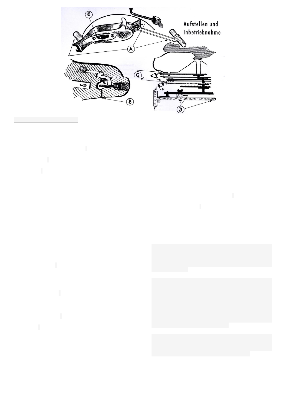
Installation and operation
The delivered music automat "telematic 200" has to be
checked for possible damage during commissioning.
Any defects found must be reported immediately to your
dealer or to us, the manufacturer. the defect notice must
be received by registered letter within 14 days of receipt
of the machine. Before you proceed to populate the unit
with records, it is necessary to remove the fuses used
for transport. We therefore ask you to use the illustration
above:
A) Remove the rubber band from the sapphire treasure
to be released in the direction of the arrow and remove
the rubber grommet of the tonearm support
B) The counterweight of the tonearm is secured to the
rear head plate with a wire clip, which must also be
removed.
C) The shafts of the two drive motors for the dial and the
magazine are protected by a rubber hose and attached.
This fuse must also be removed.
D) To prevent the mechanics from spinning, it is secured
against the intermediate floor by means of the two
designated screws. Loosen the two wing nuts and take
out the scrapers together with the wooden blocks
underneath.
E) The position of the sapphire is crucial for the correct
play of your records. Therefore, note that the swivelling
marking points to "N".
Note: We advise you to keep all removed transport
locks in a safe place. If you ever intend to change your
TELEMATIC, then protect these things from transport
disruptions. The rubber tubes pulled off the axles of the
two motors are also ideal for replacing the 60 volt bulbs
"choose", "wait" and "pay later"
The keys for the control panel and rear panel of an
automatic machine, you will find it attached to the side
handle of the rear panel.
The cash box keys are attached to the strut that
supports the mechanics in the housing.
The title paper as well as the coloured information
leaflets for "new appearances" and "hit song of the
month" are kept safe in the cash register bag during
transport.
The installation site if possible, it should not be in
front of a heater or next to an oven. In any case, care
must be taken that the sun cannot shine on the records
at any time of the day. The back of the device should be
a hand's width from the wall.
All selector pins those that may have worked their
way up during transport must be pushed down again
with the hand.
The operating voltage for the machine is 220 volts
alternating current. For other AC voltages, a 300 watt
series transformer must be used. Also make sure that
the device is connected using a Schuko socket, which
must be earthed.
Before inserting the vinyl records it is essential to
ensure that any burr residues in the centering lock of the
panels, which are caused by improper punching out of
the centering hole or protruding paint marks, must be
removed. In any case, it is advisable to use a scraper,
knife, file or the like to clean the centering lock of each
plate before use in order to avoid faults in which the
records may get stuck on the centering cone of the
centering plate after being removed.
The coin rejector only works one hundred percent if
you set up your TELEMATIC horizontally and vertically.
Do not scrub this little effort, the national rejector coin
acceptor pays off with its exact way of working

5
Description
The electrical functions
When dialing
Relay switched on
I
II
J
V
(DZ)
A
J
(DZ)
U
V
(DE)
M
H
(DZ)
(DE)
Coin engagement (normal plate)
The coin validator gives a pulse each time a 10 Pfennig piece is inserted.
The coin stacking works on the principle of the flip-flap circuit and means
that the choice is only released after the second 10 pfennig coin has
been inserted .
When the 10 pfennig coin contact MK10 is closed, the I relay picks up. If
the MK10 opens again, the short circuit of the II relay (winding I) is
released and this also picks up. If the second coin falls now, the MK10
wears again, the I relay is short-circuited and falls off. In this position: II
relay on, I relay off, the J relay is activated via the 212 - 1II and vIII
contact. This is maintained via the iI2 contact and the nsi contact on the
number plate. At the same time, the lamp "select" is switched on via the
iII2 and the 1III2 contact .
The V relay then pulls in via the iIII1 contact and the selector arm dzII
and the uI1 contact.
Dial the first digit (select group 100 or 200)
When a 1 is selected, the circuit of the J relay is interrupted, this drops
out and controls the selector DZ via the iII1 contact. If a 2 is selected as
the first number, the group contact and the short-circuit contact close.
The nsk contact short-circuits one of the two given impulses, so that the
dialler DZ stands for step 1 in both cases after the first digit. The nsg
contact allows the A relay to respond via the iII2 contact and the selector
arm dzl. This stays over the al-contact and turns on the magnet for the
second group of hundreds through the all-contact.
Dial the second digit (tens digit)
Pressing the number plate interrupts the number plate impulse contact
nsi, causing the J relay to pulse. This pulse series is transferred from the
iII1 contact to the DZ selector.
Choice of the third digit (one digit)
After the second number is selected, the V relay drops out.
Corresponding bridges in the distributor (e.g.: r, s, t, with u, o, p) connect
via the vII1 contact and use the selector arm dzII U-Relay to pull in,
which is via the uI2 contact itself holds. The uII1 contacts, so that the
next series of pulses goes from the number plate via the iII1 contact to
the DE dialler, the V relay holds over the pulses and then drops out. After
both diallers are set, the "wait" lamp lights up.
The M and H relays are now switched on via the uII contact, and the
selector and magazine motor sum is started with the mI1 and mI2
contact.
Pushing up the selection pin (storage)
The position of the two contact arms de1 and dz1 of the rotary selector,
which give the previously selected number, is directly connected to the
dial of the mechanics via the cable routing of the "A" connector. The
selector motor previously started via the ml1 contact now brings the
rotating one

6
M
H
S
S
(DZ)
(DE)
J
A
(Lp)
U
Z
(DK)
Z
J
(DZ)
S
J
Z
K
(DK)
J
Sliding contact over the attacks of the contact disc and thus short-circuits
the selector outputs del and dzl, whereby the S relay is attracted via its
winding l. Depending on the position of the all contact, the sl1 contact
energizes the selection magnet 1 or selection magnet 2. These flip the
corresponding selection pin upwards.
Reset the rotary selector
With the slll2 contact or sl2 contact, the home run of the voters is
controlled via their own SU contact (sudz or sude) and their own electoral
roll (dzll or dell). Furthermore, the sll1 contact separates the minus line to
the relays J, A, Lp, U and Z and thus they drop out. Due to the drop in
the U relay, the pulse to the selector magnet is interrupted with the ulll2
contact. The S relay will hold until both diallers are set to step 0 again.
When the S-Relay drops, the storage process ends and the device is
free for a new choice.
Description of credit storage for 50 pfennigs and 1 DM
The credit memory section built into the command device makes it
possible to play 3 to 5 records for a 50 pfennig piece and 5 to 10 records
for 1 DM. The number of plays can be changed by re-soldering bridges.
(See paragraph: change in the credit requirement)
50-pfennig Insertion
When a 50-pfennig piece is inserted, the MK 50 closes. The DK selector
takes a step and uses the dk1 contact to pull in the Z relay, which holds
itself via the zlll2 contact. The J-relay is activated by the zl2 contact and
thus the choice is released. The further selection process for the records
corresponds to that of 2 x 10 pfennig insertion.
Counting Down the established frequency of selection
After the end of the selection, the S relay picks up and switches off the Z
relay via sll2 contact. After the Z relay has dropped out, the DK selector
takes a step via the dkll selector arm and the zlll1 contact. The credit
requirement is thus reduced by one choice. The previous switching
process of the DK selector can now again pull the Z relay via the dkl
contact and issue a new credit.
This process is repeated until the selector DK, with his selector arm dkl,
for example (depending on the credit setting set) comes to the third step.
From this position, the voter returns to the zero position via the dkl train,
the kl1 contact and the sudk contact.
DM1. - Insertion
when inserting a DM1 coin, the K relay picks up first, and the DK selector
takes the first step via the Klll2 contact and switches on the J relay via
the ZIII1 contact. This means that the first record can be selected. The
further selection process corresponds to that of 2 times 10 Pfennig insert.
Counting Down the established frequency of selection
The reduction in the selection option corresponds to the same
procedures as with the 50 Pfennig insertion. The voter now only runs
after the sixth step, for example, due to the now open kl1 contact on the
eleventh step. This short-circuits the K relay and drops out. The DK
selector only returns to its zero position after the K relay has dropped out.

7
Change in Credit Settings .
Possible credit change
a) 2 x 10 Pfg. 1 PLAY –50 Pfg. 3 PLAY –DM 1 –6 PLAY
b) 2 x 10 Pfg. 1 PLAY –50 Pfg. 3 PLAY –DM 1 –7 PLAY
c) 2 x 10 Pfg. 1 PLAY –50 Pfg. 4 PLAY –DM 1 –8 PLAY
d) 2 x 10 Pfg. 1 PLAY –50 Pfg. 5 PLAY –DM 1 –10 PLAY
With 1 play for 1 x 10 Pfg. regardless of which credit is required for 50 Pfg. or DM 1 - is selected to connect A & B of the terminal block.
In addition, the two red and pink wires from the coin switch on the terminal block must be exchanged.
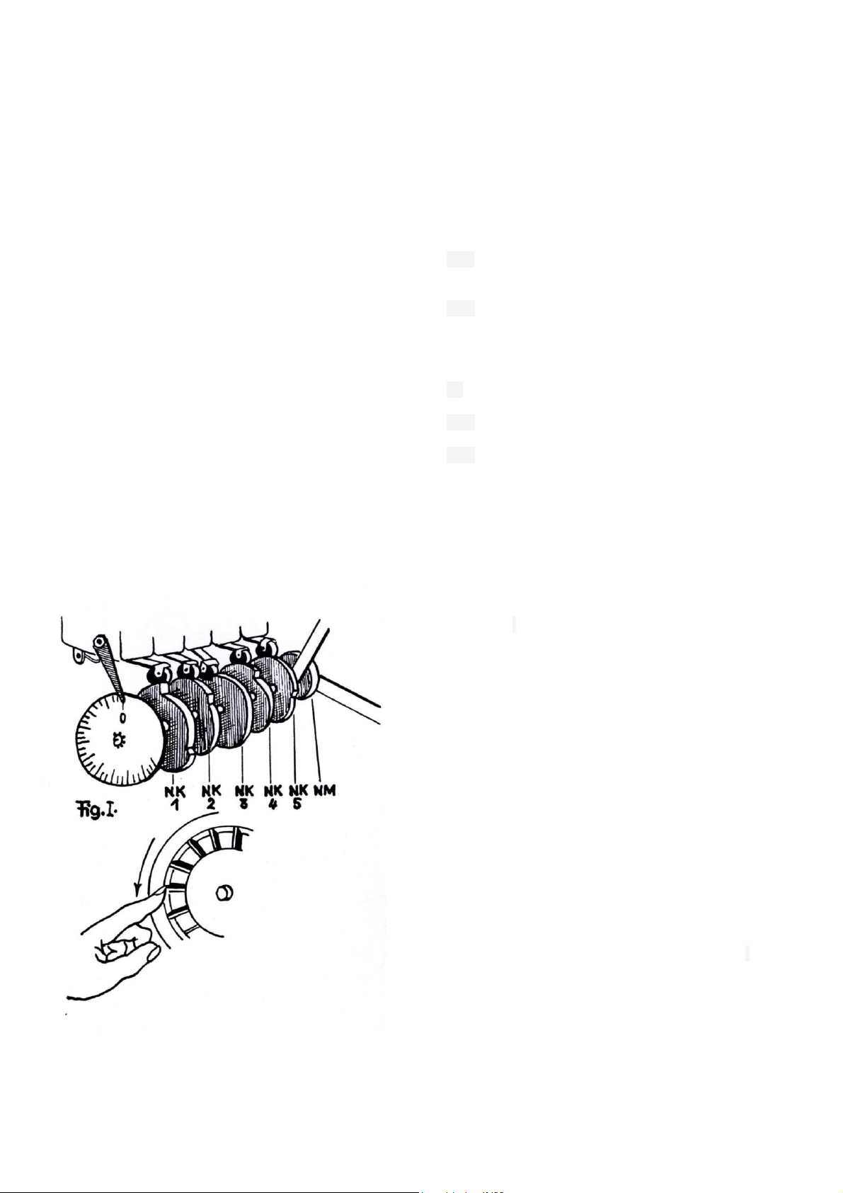
Necessary bridge connections on the terminal block
The desired change in the frequency of
failure for 50 Pfg. and DM 1. - is carried out
on the floor-facing terminal strip of the
command device. (See Fig 1)
The change provided can be carried out on
the two lower rows of solder pins, which are
labelled A - F in our diagrams
Example a)
Example b)
Example c)
Example d)
Equipping with LPs
Setting the command device
On the upper terminal block of the command
device (see fig I) lie solder pins connected in
pairs on the right and left. When viewed
horizontally, they represent tap number 7, 8, 9
and 10 of the DZ selector. This precaution
makes it possible to equip the machine with
either, 10, 20, 30 or 40 long boards.

8
If you would like to expand your vinyl record
equipment in this way, you only need to change the
bridge connections on the connection strip as
shown in the illustration.
As an example:
If the music machine is to be equipped with 10 LPs,
the bridges between d and h and qu and u must be
removed. Then qu is connected to the soldering lug
on the left. With an expansion to 20, 30 and 40 LPs,
the connections above can also be changed.
Description of the electrical function
When choosing a long-playing record
RELAY
I
LP
Coin insertion
If a coin insert of 3 times 10 Pfennigs is inserted before the choice of a long-playing
record, the electrical switching operations up to the second 10 Pfennig piece are the
same as those described under "coin insert normal record". In the order of the
switching sequence, the: I, II, J, and V relays have already been actuated.
If the MK 10 opens again after the second 10 Pfennig piece, the II relay drops out and
the stacking relays are prepared for receiving the third coin pulse. When the third coin
is inserted, the I relay picks up again and, via the IL1 and 1III and 1III2 contacts, brings
the LP relay to the suit. The LP relay maintains contact via its own LpII2 and connects
the outputs of the DZ selectors. At the same time, the connection to the lamp “pay
more”is interrupted via the LpIII1 contact. The selection of the record is possible.
Pay More appears
If you already select a long-playing record from an existing credit due to the previous
insertion of 50 Pfennigs or 1, - DM, the lamp "pay more" lights up. This process is
explained by the fact that the Lp relay (depending on the number of bridges on the
connecting strip for long-playing records, with the IpI1, IpI2, IpIII1 or IpIII2 contact)
interrupts the connection from the tap of the DZ selector to the dial of the mechanics.
The lamp "Pay More" is switched on via the dialer dzII and the IpII1 contact. If a 10
Pfennig piece is thrown, the Lp relay responds, the IpII1 contact interrupts "Pay More"
and, depending on the number of the selected plate, the IpI1, the IpI2, the IpIII1 or
IpIII2 contact connects the selector output with the mechanical dial. The desired record
is selected.
The error button
The error button returns the memory to the starting position in the event of a wrong
choice or an operating error, but without erasing the loan. by pressing the error button,
the L-relay speaks and lasts until the home run of the selector ends, S relay has
dropped out and the sII1 contact is opened. The LII2 contact holds the J, V, I and II
relays over the time the S relay is energized so that the credit is not lost.
Disc Nr. 160-269
Disc Nr. 170-279
Disc Nr. 180-289
Disc Nr. 190-299

9
Description of the electrical
functions when changing records
Record Lift
When the selection of the desired record
(raised selector pin) is complete, the magazine
motor, controlled via the MI2 contact, moves
the record magazine with the MSK contact
against the selector pin raised up.
At the moment of contact between the
insulated brass bracket (MSK contact) on the
record magazine and the selector pin, the
resulting earth connection (plus) switches on
the W relay, which holds itself via the wIII2
contact. At the same time, the wIII1 contact
causes the M relay to drop out.
By switching the wI1 contact to the wI2 contact,
the magazine motor is switched off and the
player motor is switched on. The brake
connected in line with the player motor also
applies. By releasing the brake, the lift spring
acts, which takes over the gear transmission to
transport the record into the play position.
The following electrical switching functions are
carried out by the cam contacts NK1 to NK5 on
the changeover gear during lifting.
1) By switching the NK1:
a) the magazine motor is interrupted again
and
b) prepared the return of the player engine
2) The NK2 closes and prepares the switching
on of the M relay for the later return.
3) By switching NK4, the centering magnet
picks up.
4) The NK5 closes and prepares to switch on
the reset magnet.
5) By switching back the NK4:
a) the centering magnet is switched off so
that the record can be pressed against the
turntable by the centering plate using spring
pressure.
b) The reset magnet is switched on.
6) The NK5 opens and brings the reset magnet
to waste.
7) The NK3 controls the muting of the amplifier
when the plate is changed, so that the
placement of the tonearm and the brushing of
the sapphire are not transferred. As a last
function, when a plate is placed on the NK3, a
relay in the amplifier is interrupted, which drops
out after a delay and switches on the anode
voltage.
Return the played record
The tonearm switch-off contact is located on
the back of the pickup. When the record is
played, i.e. when leaving the lead out groove,
the switch-off spring touches the TA contact
and causes the W relay to drop out due to the
resulting mass connection by short-circuiting it
via a resistor. The M relay receives voltage via
the wIII1 contact and picks up. At the same
time, the player motor is repositioned via the
wI1 contact, which in turn actuates the cams
NK1 to NK5 and the cams NM via the gearbox.
In that the returning lifter returns the records to
the record magazine, the switching sequence
of the cam contacts is in the reverse order to
when the records were placed. when the
player motor runs out, the NK1 switches over
and starts up via the mI2 contact cdn
magazine motor, and also moves the selector
motor via the mI1 contact. When the record
magazine rotates, the NK7 cam contact is
opened briefly, causing the M relay to drop out
(selector motor switched off).
After a further full turn, the shut-off cam of the
record magazine actuates the NK6, opens it
briefly, and also stops the magazine motor via
the deactivated relay.
If several records have been selected, the
same procedure as described will be repeated
after the return of the first record has ended.
The magazine motor moves the MSK contact
against the high-positioned selector pin, the W
relay picks up again, etc.
10

11
12
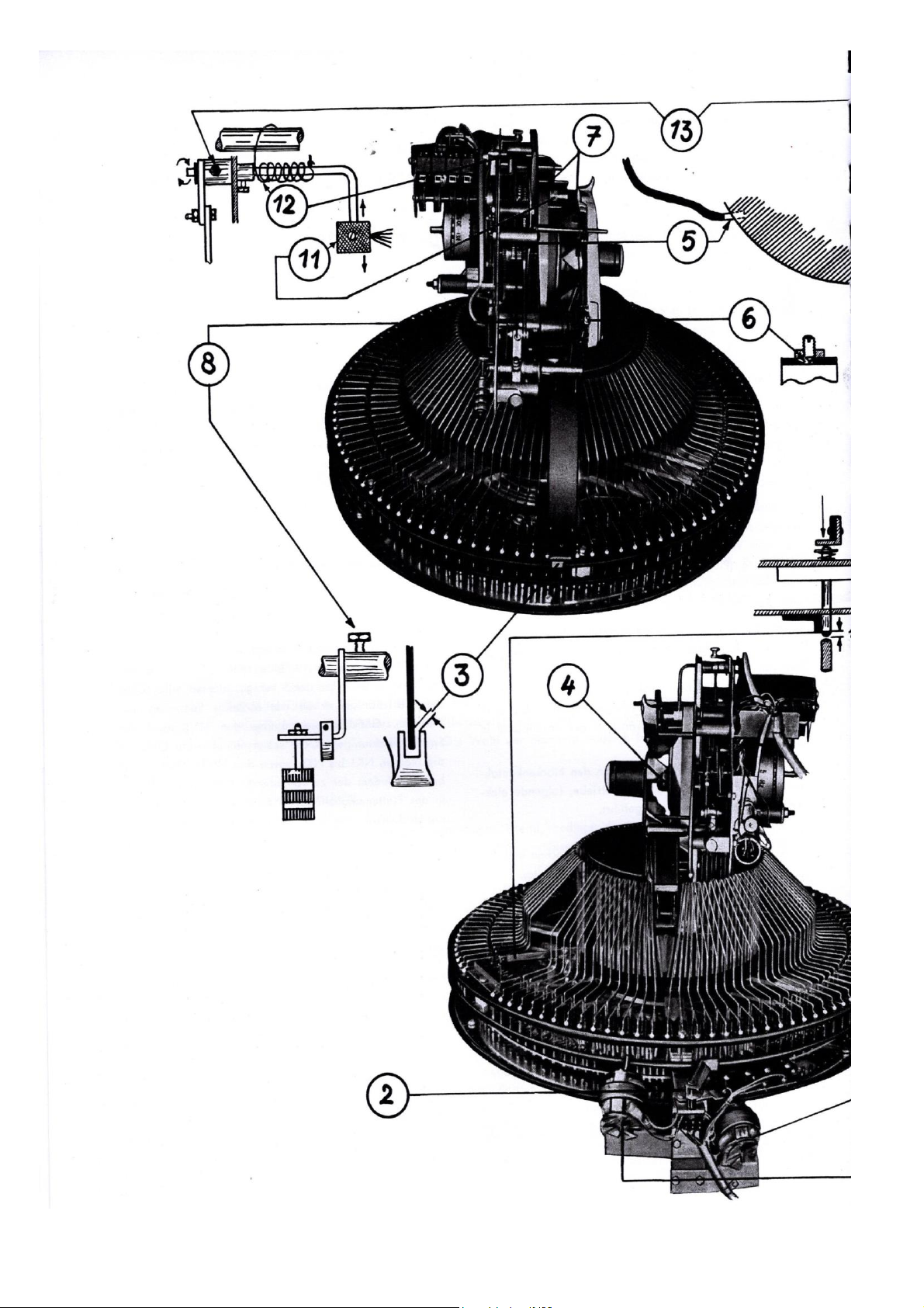
Adjustment regulation for the "telematik 200"
(The numbers of the individual positions refer to the
picture on page 10/11)
RAISING AND LOWERING THE RECORD
(Adjustments 1 - 5 are follow-up adjustments and must
be done in the specified order)
1. The record bracket:
the record brackets should stand vertically on the
record magazine while the front part of it should lie
horizontally to the magazine.
Adjustment: Align to the side or to the front with
adjusting pliers.
2. Setting the drum:
While the record magazine is hitting a selection
pin the record should be parallel to the chassis.
Adjustment: Adjust the anchor bracket of the
selection drum in the slot.
3. Lateral position of the lifters:
The turntable rotating with the record should be in
the middle the lift fork run. When entering the record
compartment should do not touch the lifting fork on the
side of the plate bracket.
adjustment: lift axis within the lift drive lever move
axially or bend the lifter accordingly
to adjust.
Note: To make this adjustment easier, too
adjustment no. 2 should be corrected
4. Press on the record:
When the plate is in the play position, the magnetic
core of the centering plate should have a lot of tolerance
on all sides, up and down.
Adjustment: Loosen the two fastening screws of the
heart disk and adjust the heart letter with the centering
magnet.
5. Centering the record:
In the play position, the distance between the edge of
the plate and the lifter or tipper should be 2-3 mm.
Adjustment: adjust the lift stop screw and the
eccentric tipper stop accordingly.
Note: This adjustment is for the front and back of
the make playing plate.
ADJUSTMENT OF THE SWITCHING CAMS
The control of important electrical switching sequences
when playing and changing the records is done by the
cam contacts NK1 - NK7 (microswitches) attached to the
rear of the playing chassis and to the side of the record
magazine. The mechanical cam for actuating the
tonearm and the sapphire brush, which is called NM in
our explanations, is also attached behind the switch NK5.
The switching functions of the respective cams are:
NK1 switching magazine - player motor
NK2 timer in conjunction with switches NK6 and NK7
(dial and record magazine run out)
NK3 mute (turn on and off the anode voltage of the
amplifier)
NK4 magnet for plate centering
NK5 reset magnet for selector pin
NM Mechanical control of the tonearm movement to the
record and back as well as actuation and the sapphire
brush.
Important NOTE!
The setting instructions below for the cam contacts NK1
to NK5 and for the cam NM are only valid for devices
with a manufacturing number exceeding 11500. In this
version, the tonearm control rail according to Fig. II is
changed at the same time.
In the previous series with the tonearm control rail
according to Fig. III, deviating from the specified
adjustment regulation, the NK4 has to switch to 48 at
rest, while at 25 the cam NM should move the tonearm
control rail so far that the inner one.

13
Cut out the same with the tip of the tonearm control cone
(see Fig IV)
A check of the correct switching torques of the individual
cam contacts and the prescribed triggering of the
tonearm control rail by the cam NM must be carried out
using the setting pointer and the dial.
For this purpose, let a record run in the playback
position and then interrupt the power supply to the
device. If, as in Fig. I, the player changer motor turns in
the direction of the arrow, the following switching torques
must result in the range of 10 –240:
At 10
NK3 work
NK5 rest
At 55
Tonearm control lever aligns with the camshaft and switching pin of the NM. See Fig V
At 68
NK4 rest
At 230
NK2 rest
At 240
NK1 rest
In addition, in this position the lifters should end with the outer edge of the record magazine.
At 250
End of lifting spout
A necessary adjustment of the cam contacts NK1 to
NK5 is done by adjusting and the shutter cams, the two
pressure screws of which must be tightened firmly
against the camshaft after the setting has been
completed.
Is the trigger point of the switch between "rest"
and "work" is not on the middle of the support surface
(see Fig. VI), the shifting tongue of the same must be
adjusted accordingly by bending.
Figure VII shows the rest position of the NK, while its
working position can be seen in Figure VIII.

14
TONE ARM ADJUSTMENTS
(Adjustments 6 - 13 are follow-up adjustments and must
be carried out in the order listed)
6. Tonearm tip bearing:
The tonearm must be slightly stored in the tip bearing
without any play on the side.
Adjustment: After loosening the lock nut, adjust a
bearing screw.
7. Sagging of the tonearm:
When the mechanics are in the playing position, the
tonearm should sag so that there is a 3-5 mm distance
between the record and the needle.
Adjustment: adjust the height adjustment screw of the
tonearm accordingly.
8. Point of attachment of the needle:
The needle should be placed 2 - 3.5 mm from the edge
of the plate.
Adjustment: Loosen the pressure screw of the balance
flange and change the angular position of the balance
weight flange to the tonearm accordingly.
Note: Make sure that the tonearm axis has enough axial
play when making this adjustment.
9.Tonarm-balance weight:
The tonearm should always have a small torque
upwards, just enough to move it back to its original
position when it is lifted off the plate.
Adjustment: shift balance weight accordingly.
Note: It is important to ensure that due to probable.
mechanical inhibitions, the balance weight is not being
adjusted too tight to satisfy this adjustment.
10 switch-off position of the tonearm:
The tonearm should switch off when the needle is 35
mm from the edge of the plate.
Adjustment: Swivel the switch-off contact accordingly.
11. Brush distance:
When the mechanism is at the rest position, the needle
should just pass the brush.
Adjustment:
a) Adjust the brush holder with adjusting pliers
accordingly.
b) Move the brush on the holder accordingly.
12. Brush reset force:
Adjustment: The torsion spring should be pretensioned
about five turns.
13. End position of the brush:
When the mechanism are at rest, the brush should be
pivoted about 3 mm past the needle.
Adjustment: Twist the brush holder within the operating
lever.
14. Contact pressure of the magazine motor:
The magazine motor should press so hard on the
rubbing edge of the magazine that it is driven safely. The
contact pressure must not be so strong that the motor
can no longer start when the magazine is locked.
Adjustment: Adjust the fastening screw of the pressure
leaf spring accordingly.
15. Selector magnet working position:
When the selection magnet is actuated, the selector
plunger should be raised about 6 - 7 mm above the
selector disc.
Adjustment: After loosening its fastening screw, adjust
the push lever in the hole.
16. Selector magnet rest position:
a) When in position, the tappet should rest about 0.5 mm
above the dial, so that the tappet can pivot without
touching the dial.
b) There should be a tolerance of approx. 5 mm
between the tappet and the push lever.
Adjustment:
a) Move the bearing bush of the selector plunger axially
after loosening the pressure screw.
b) After loosening its fastening screw, adjust the back
stop on the selector magnet accordingly.
17. Reset force and torque of the tappet:
After actuation, the selector plunger should safely return
to its initial position. If it is influenced laterally, it should
also swivel back safely.
Adjustment: Turn and move the adjusting ring of the
plunger spring on the selector plunger accordingly.
18. Contact pressure of the selector motor:
The selector motor should press so hard on the rim of
the dial that it is driven safely. The contact pressure
must not be so strong that the motor can no longer start
when the selector is locked.
Adjustment: Adjust the fixing screw of the pressure leaf
spring accordingly.
19. Selection contact loop:
The two sliding contacts should sag about 1 mm. The
contact pressure of the grinding wheel must be slightly
stronger than the contact pressure of the sliding contacts.
20. Contact disc:
The plunger should shoot up the selection pin cleanly
without touching the previous or subsequent selection
pin.
Adjustment: Move the fastening bolt of the sliding
contact in the slot accordingly.
21. Return magnet stroke:
When the reset magnet is actuated, the reset plunger
should bump up to about 1 mm below the magazine stop.
Adjustment: When the reset magnet is actuated, adjust
the push lever in its slot accordingly.
22. Return magnet rest position:
In the rest position, there should be a tolerance of
around 0.5 mm between the push lever and the return
push rod.
Adjustment: After loosening its fastening screw, adjust
the back stop of the reset magnet

15
Description of the mechanical functions when changing records
Centre
the upward movement of the lifter is limited
by the lifter stop screw which, in
conjunction with the setting of the eccentric
tipper stop, enables the centering of the
record. The centering hole of the record
should be slightly below the centering cone
of the centering plate so that the plate is
lifted off the lifting fork and the tipper when
it is mounted on the plate.
Clutch pinion and turntable drive
After the lifter is pivoted into the play
position, the further drive on the gear is
taken over by the tension spring which is
hooked onto the stop angle of the
gearwheel shown in FIG. 1.
The stop of the large gear is limited by the
stop pin B. The coupling sleeve C (FIG. 1)
is now screwed out of the engagement of
the large gearwheel like a screw by the
constantly acting friction of the felt strip D.
The player motor now has the task of
driving the turntable via the axis F and the
rubber intermediate wheel G (Fig. 2). The
drive surface of this friction wheel is inside
the platter.
The idler gear is pulled against the drive
shaft of the motor and the running edge of
the platter via the spring shown under J
(Fig. 2). If the player motor is reversed
after the record has been played, the
brake H (Fig. 2) mounted inside the
turntable prevents it from rotating in the
normal direction.
Returns
With the polarity reversal of the player motor and due to the brake loop D, the clutch pinion moves back into the
engagement of the large drive gear. the motor now acts via the gearwheel gear winds the lift pull chains onto the roller of
the large gearwheel and thereby returns the plate lifter to the starting position. Due to the return of the lifters, the played
record is placed in the plate magazine and the lifter tension spring is preloaded again. The magnetic brake, which has
now fallen off, prevents the spring-loaded mechanism from moving the plate lifter inwards again thanks to the brake
rubber placed on the jacket of the player's motor.
How the plate lifters work
The drive of the plate lifter,
which takes over the transport
of the record into the play
position, is taken over by the
tension spring connected to the
two lifter drive levers. In the
rest position of this spring is
tensioned on train. When the
plate magazine with the MSK
contact that rotates after the
selection touches the shifted
stylus, relays switch on the
player motor and apply the
magnetic brake. the axis of the
player motor moves the two
gearwheels from the
transmission via the clutch
sprocket C (see Fig. 1) and
allows the wound-up pull
chains A (see Fig. 1) of the
lifters to run off. At the same
time, the lifter tension spring
starts to operate and,
depending on the traction chain
that is running, pulls the lifter
inwards.
While one lifter now runs against
a plate bracket and thus locks
the plate magazine, the other
lifter lifts a plate out of the
magazine and pushes it upwards
on the tipper. If necessary, the
tipper is swivelled from the plate
to the corresponding
side .

16
Interference sources –Diagnosis
Before dialling
Lights up after inserting money
"Select" lamp not on.
Bulb broken or no contact.
Power supply fuse defective.
Coin contact does not work because it
is defective or jammed.
change
change
replace or readjust if necessary
"Select" lamp burns constantly
and you can play without money.
Coin hangs on the coin switch.
Coin switch always switched on
because it is jammed.
Remove
readjust or replace
The record lifter runs upwards
without a selection being made.
Ground connection of the MSK contact
(yellow connecting wire)
check with measuring instrument
Selector magnet attracts
continuously.
Defect at the condenser C4 in the
command device.
change
Reset magnet is attracted
Defective cam switch NK5.
Switch burnt due to missing spark
suppressor capacitor.
Reset button stuck on the cabinet is
stuck
Install spark suppressor if
necessary
change
The fuse of the power supply
blows continuously
The two sliding contacts under the
tipper bracket are connected (plus with
minus).
Centring solenoid or reset solenoid
defective.
readjust
change
Both record lifters swing against
the plate magazine and back.
The magnetic brake on the player
motor is too low.
Brake pad damaged or loose
readjust
change
After dialing
Both selection magnets fire at the
same time.
The contact fingers of the lower double
sliding contact have a connection.
Possibly. jumped out of the track
during transport.
readjust
Dial magnet No. 100 or No. 200
shoots without pushing up a dial
pin.
The locking spring of the switching pin
has broken off or slipped out of the
guide bush.
The plunger flag is therefore
transverse.
replace or readjust
The dial disc or record magazine
does not start
Broken rubber buffer to fasten the
selector or magazine motor.
Drive rubber on the dial or magazine
disc defective. Leaf spring, the motor
presses, too little tension.
change
readjust
The centred plate does not pick
up the record.
Adjustment 4 and 5 is not correct, lift
stop screw and tipper stop adjusted.
The centre hole of the record was not
cleaned of any burrs or varnish
residues before using -
Check adjustment no. 4 and 5
Clean the centre hole of the plate
Centering magnet does not
respond
Coil defective (fuse of the power pack
blows).
Cam contact NK 4 does not switch.
Readjust or replace
Selection pin does not raise
Contact disc dirty.
Sliding contact on one side no support
Clean and readjust with switch
cleaner spray
Tonearm jumps when it touches
the record.
The clutch pinion is too quickly
removed from the engagement of the
large gear due to the felt of the brake
rod, which is too tight.
Mechanical jamming in the gearbox,
for example, tooth engagement of the
clutch pinion too deep
relax the brake rod
Move the player engine sideways
accordingly
Tonearm sets down too early or
too late or switches off too early
or too late
Tonearm-balance-flange misadjusted.
Tonearm switch-off contact
misadjusted
readjust
readjust

17
When changing
The record returns to the wrong
compartment.
Two records clamp on to the
centering plate
When lowering, the plate remains on
the centering plate, the centre hole of
the plate is too tight.
scrape out
Tonearm switches off, record
does not go back with the lifter
Brake rod has too little tension, the
clutch sprocket is not deflected and
does not bring the lifters back via the
gear ratio.
tighten slightly
Lifts don’t move out of the record
magazine all the way back and
the selection disc runs
The clutch gear is not sufficiently firmly
gripped by the compression spring on
the clutch sleeve
Tension the spring or replace it
Sapphire is not cleaned from the
brush.
Thrust shackle pin of cam NM slipped,
torsion spring broken.
Mount
change
While playing
Sound fluctuates, even though
the record plays correctly centred.
Rubber idler gear oiled or stiff on
bearing axle. Running rim in the
turntable dirty or oiled. Greased axis of
the player motor, tension spring for
friction wheel too little tension
Remove
clean with tetra
change
tighten
Strong humming while playing
Transport security of the mechanism
not loose.
Bass adjustment too strong in relation
to the volume.
Remove or adjust
Played disc runs backwards.
Return stop in turntable defective
replace
Disc does not switch off.
Tonearm switch-off contact dirty
clean with tetra
Dialler is not deleted.
Reset magnet coil defective.
Cam contact NK 5 does not work.
Switch pin worn
change
adjust if necessary
lightly grease
General electrical switching problems
We recommend a routine check in the following order:
1. Check the defective switching element, such as the motor or solenoid, for mechanical jamming.
2. Check the faulty switching element for electrical interruption or short to ground.
3. Check the relevant lines, especially the clamp connections, sliding contacts and plug connections
for loose contacts, wire breaks and short to ground.
4. Using the description of the "electrical functions" when selecting or changing, check whether the
designated relays pick up in the corresponding changeover position.
5. Check whether the normally open contacts of the relays close properly and sufficiently interrupt the
normally closed contacts.
6. Check whether the working contacts of the relays that have not been energized interrupt
sufficiently and the rest contacts of the relays close properly.

18
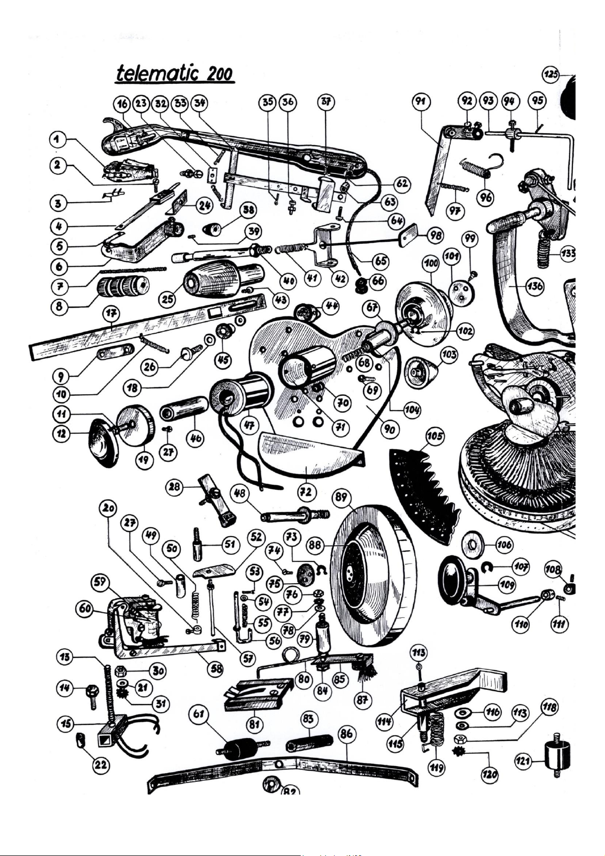
Individual parts of the mechanics "telematic
200"
1 KST 11 crystal system
2 Screw M2 x 12 DIN 85A
3 Micro sapphire SM11
- Diamond needle for KST 11 crystal system
4 Contact spring
5 Contact sheet
6 Compensation lever
7 Threaded rod M4 x 60
8 Counterbalance
9 Sliding plate
10 Tension spring (valid until serial number 11 499)
11 Guide bolts
12 Coil cover
13 M4 x 55 threaded rod
14 S.K. Screw M4 x 20 Din 933
15 Contact holder cpl. with contact finger
16 Tonearm
17 Tonearm rail (valid up to serial number 11 499)
- Tonearm rail (valid up to serial number 11 500)
18 U-washer 6
19 Coil cap
20 Collar with screw
21 U-washer 4
22 D socket
23 Screw M3 x 15 DIN 85 A
24 Angle
25 Tonearm bearing
26 Screw M4 x 12 DIN 85 A
27 Screw M3 x 3 DIN 86
28 Brake
29 S.K. Screw M3 x 8 DIN 933
30 Nut M4 DIN 934
31 Toothed washer F.Z.A. 4 DIN 6797
32 Holding Brackets
33 Tension spring
34 Tonearm carrier
35 Spin 1 x 5 DIN 94
36 M 3 x 10 DIN 85 A screw
37 Tonearm centering screw
38 Tonearm cones (valid up to serial number 11 499)
- The tonearm cone 4 - 17 is omitted for devices
from serial number 11 500
39 Setscrew M2 x 4
40 Threaded tube (valid up to serial number 11 499)
- Threaded tube (valid from serial number 11 500)
41 Tension spring
42 Tonearm holder
43 Screw M3 x 6 DIN 85 A
44 Plate guide with lateral Hole for the cable
passage d. centering magnets
45 D sleeve
46 Core sleeve
47 T 200 centering coil
48 Axis for turntables
49 Guide sleeves for lower switching pin
50 Compression spring (W magnet No. 100)
-Compression spring (W magnet Nr 200)
51 Stop bolt
52 Pestle flag
53 Split pin 1 x 8 DIN 94
54 U disc 3
55 Compression spring
56 Upper switching pin
57 Lower switching pin
58 Shift lever assy.
59 Coil for reset magnet 60 Ohm
60 Coil for optional magnet 90 Ohm
61 Conti buffer 21 239
62 Mega buffers
63 Threaded tube
64 M 3 x 4 DIN 85 A screw
65 Tonearm braided flex
66 Rubber grommet
67 Felt ring
68 Coil spring
69 Phillips screw 4.2 x 13
70 Rubber grommet
71 Coil sheath cpl
72 Cover plate
73 Seeger ring 6 x 0.7 DIN 471
74 Countersunk screw M3 x 5 DIN 63
75 Turntable disc
76 Mother M4
77 Tooth lock washer F.Z.A. 4 DIN 6797
78 Washer 4
79 D - sleeve
80 Spring hooks
81 Contact rotor cpl
-Contact spring
82 Washer 25 x 6 x 1
83 Intermediate piece
84 S.K. M4 x 40 screw
85 + 87 brush holder cpl. with brush
-Brush
86 Strut
88 Rubber ring
89 Turntables
90 Front cover plate
91 Bracket compl.
92 S.K. Screw M3 x 8
93 Brush rod
94 Collar with screw
95 S - dowel pin 1 8 DIN 1481
96 Torsion spring
97 Tension spring
98 Pressure piece cpl. (valid until serial number 11
499)
- Push pin (valid from serial number 11 500)
99 Self-tapping screw 4 x 6.5 DIN 7975
100 Plate centering
101 Disc
102 Seeger ring 6 x 0.7 DIN 471
103 Plate guide (metal coating)

19
104 Coil core
105 Upper plate holder segment
(Specify number range)
106 Felt disc
107 Seeger ring 4.5
108 Collar
109 Intermediate wheel cpl.
110 Collar
111 Setscrew M3 x 5
112 Tension spring
113 Split pin 1 x 15 DIN 94
114 Locking lever
115 Bearing bolts
116 U disk 16 x 5.2 x 1
117 Washer 5
118 Nut M5 DIN 934
119 Torsion spring
120 Tooth washers F.Z.A. 5 DIN 6797
121 Conti buffer 20 292 FJ 95
122 T 200 magazine motor (shaft offset at the front)
122a T 200 selector motor (cylindrical shaft)
123 Mega buffer 781 002
124 Leaf spring
125 Clamp
126 Quenching capacitor 2 x 0.5 MF
127 Bracket for wiring harness
128 Brushes
129 Grub screw M3 x 5
130 Knurled screw M3 x 5 DIN 464
131 Angle bracket
132 Chain holder
133 Tension spring
134 D sleeve
135 Pull chain
136 Lifter (left) cpl.
137 Bearing bush
138 S.K. Screw M5 x 50 DIN 931
139 Circlip D8 (seeger)
140 Gear plate
141 Gear
142 Condenser CO - MP 35 - 4.5 C - 220 V.
(BOSCH)
143 Angles
144 Sliding resistance 1000 ohms 12 watts
145 Holders
146 M4 x 10 DIN 85 A screw
147 Microswitch 925 R
148 Tippers
149 Small spacer sleeve
150 Tipper axle
151 Cover plate
152 Microswitch 925 R
153 Threaded bolts M 3.5
154 U washer 3.7 DIN 433
155 Nut M 3.5 DIN 934
156 Adjusting washer
157 Tooth lock washer F.Z A. 3.7 DIN 6797
158 Cams
159 Hands
160 Tension spring
161 Gear w. chain roller
162 Gear plate
163 Setscrew M4 x 10 DIN 553
164 Control disc
165 Square screw
166 Cams
167 Papal motor without clutch
168 Adjusting screw
169 Pull rod
170 Brake ring
171 Clutch with pinion
172 Coil for magnetic brake 5 - 55
173 Turnbuckle nut
174 Lever (valid for serial number 11 499)
174a Lever (valid for serial number 11 500)
175 Grub screw M6 x 15 DIN 913
176 Magnetic brake
177 S.K. Screw M4 x 20 DIN 933
178 Tension spring
179 Felt
180 Cap for lift
181 Lifter (right) cpl.
182 Screw M3 x 6 DIN 85 A
183 Mounting bracket
184 Insulating washer 16 x 1
185 Brake rod cpl.
186 U disc 1 x 6 x 20
187 Threaded rod M4 x 100
188 Mother M4
189 Eccentrics
190 2-pole push button switch
191 Push button
192 Brake rod
193 Large spacer sleeve
194 Toggle switch (Marquard) No. 100 NT
195 Plate baffle
196 Plate bracket
197 Holding tube
198 Pearl
199 Drive rubber f. Record magazine u. dial
20
This manual suits for next models
3
Table of contents
Popular Jukebox manuals by other brands

Philips
Philips HDD6330 GoGear quick start guide

Grace Digital
Grace Digital Victoria Jukebox GDI-JBP100 user guide

Crosley
Crosley CR11 instruction manual

Wurlitzer
Wurlitzer One More Time CD operating instructions

Philips
Philips HDD120 Specifications

Innovative Technology
Innovative Technology VJB-125 instruction manual


