DITEC COM E User manual

DITEC S.p.A.
Via Mons. Banfi, 3 - 21042 Caronno Pertusella (VA) - ITALY
Tel. +39 02 963911 - Fax +39 02 9650314
www.ditec.it - [email protected]
COM E IP1775
rev. 2007-11-23
Istruzioni
d’uso selettore
di funzioni
elettronico
PEDFGBI
Operating
instructions
for electronic
function selector
Mode d’emploi
du sélecteur
de fonctions
électronique
Betriebsanleitung
für elektronischen
Programmschalter
Instrucciones
de uso selector
de funciones
electrónico
Instruções de
uso do selector
de funções
electrônico
Fig. 1
RESET
CONTROL PANEL
COM
COM
1
OP
OPEN
KEY
TELRC
(optional) ERASE
DOWNLOAD
KEY
J2J1 J3
J4
22
21
1
0
21
22
0
1
max. 4,5 m (ComE supplied cable)
A
P
RESET
CONTROL PANEL
COM
COM
1
OP
OPEN
KEY
TELRC
(optional) ERASE
DOWNLOAD
KEY
J2J1 J3
J4
22
21
1
0
21
22
0
1
Shielded cable = Max 50 m
Unshielded cable = Max 5 m
P
Fig. 2

2
COM E - IP1775
COM E
DMCS
jack
1
4 5 6
3
2
82
82
COM E
52
COM ED
COM AD
DMCS
jack
1
4 5 6
3
2
80
COM ED + COM AD
80
52
Fig. 3 Fig. 4

3COM E - IP1775
COM E
1
4 5 6
3
2
CONTROL PANEL
COM
21
22
0
1
CONTROL PANEL
COM
21
22
0
1
F
1
4 5 6
3
21
4 5 6
3
2
COM E
CONTROL PANEL
COM
21
22
0
1
Fig. 5
Fig. 6

4
COM E - IP1775
COM E
1
4 5 6
3
2
COM E
1
4 5 6
3
2
CONTROL PANEL
COM
21
22
0
1
CONTROL PANEL
COM
21
22
0
1
CONTROL PANEL
COM
21
22
0
1
CONTROL PANEL
COM
21
22
0
1
X
X
Fig. 7

5COM E - IP1775
I
AVVERTENZE GENERALI PER LA SICUREZZA
Il presente manuale di installazione è rivolto esclusivamente a
personale professionalmente competente. Leggere attentamente
le istruzioni prima di iniziare l’installazione del prodotto. I materiali
dell’imballaggio (plastica, polistirolo, ecc.) non vanno dispersi nel-
l’ambiente e non devono essere lasciati alla portata dei bambini in
quanto potenziali fonti di pericolo. Prima di iniziare l’installazione
verificare l’integrità del prodotto. Per l’eventuale riparazione o
sostituzione dei prodotti dovranno essere utilizzati esclusivamente
ricambi originali. E’ necessario conservare queste istruzioni e
trasmetterle ad eventuali subentranti nell’uso dell’impianto.
1. DATI TECNICI
Grado di protezione IP43;
Temperatura -20 °C / +55 °C
2. INSTALLAZIONE
Fissare il selettore di funzioni nelle vicinanze dell’automazione
in posizione sicura e adeguata all’uso.
N.B.: è possibile fissare il selettore di funzioni incassato a muro
su scatole circolari, non di nostra fornitura.
3. COLLEGAMENTI ELETTRICI
- Eseguire i collegamenti elettrici indicati in fig. 1 oppure 2.
Fino a 5 m di distanza, ed in assenza di disturbi ambientali, non
è necessario usare il cavo schermato.
Se si usa il cavo [A] in dotazione, collegato al connettore COM,
non si devono collegare i morsetti 0-1-21-22 al quadro elettronico.
- Con un unico selettore è possibile impostare le medesime
modalità di funzionamento in due automazioni, eseguendo
i collegamenti elettrici indicati in fig. 5.
- E’ possibile collegare due selettori ad un’unica automazi-
one, come indicato in fig. 6.
- E’ inoltre possibile collegare uno o due selettori per impostare
le medesime modalità di funzionamento fino a massimo
quattro automazioni (no ridondanti), come indicato in fig. 7.
N.B.: per effettuare il collegamento in rete dei quadri elettronici,
usare cavo schermato [F] per trasmissione dati (non di nostra
fornitura), per una lunghezza massima complessiva di 1000 m.
Quando il selettore gestisce più di due automazioni, tagliare la
resistenza [X] presente nei quadri elettronici intermedi (fig. 7).
- Il collegamento dell’automazione al personal computer,
mediante il software DMCS, è accessibile togliendo il
frontalino del selettore (DMCS Jack - fig. 3). Seguendo le
indicazioni contenute nel manuale del software DMCS, è
possibile monitorare e controllare l’automazione mediante
il personal computer.
3.1 Comandi
Comando Descrizione
1 OP
OPEN: consente di aprire l’automazione
in qualsiasi modalità di funzionamento del
selettore.
N.B.: se la modalità di funzionamento sele-
zionata è STOP, il comando OPEN avvia la
sequenza di chiusura notturna ritardata.
1 KEY
KEY: aprendo il contatto, il selettore viene
disabilitato.
Attenzione: se si collega un comando (N.C.),
togliere il ponticello [P].
RESET RESET: elimina il codice impostato nel
selettore.
3.2 Selezioni
J1 = ON
Chiusura notturna ritardata
Durata di 10 s della sequenza
bidirezionale.
J1 = OFF
Chiusura notturna ritardata
Durata di 60 s della sequenza
bidirezionale.
J2 = ON
Apertura normale
Comando OPEN impulsivo
J2 = OFF
Apertura di emergenza
Mantenendo premuto il coman-
do OPEN, il selettore di funzioni
viene impostato nella modalità
porta aperta.
N.B.: se la modalità di funzio-
namento selezionata è STOP,
il comando OPEN avvia la
sequenza di chiusura notturna
ritardata.
J3 = ON
Abilitazione codice
E’ possibile impostare o elimi-
nare il codice di accesso.
J3 = OFF
Disabilitazione codice
Non è possibile impostare o
eliminare il codice di accesso.
J4 = ON
Jack DMCS abilitato
J4 = OFF
Jack DMCS disabilitato
3.3 Segnalazioni
LED ROSSO SPENTO
- Il selettore è funzionante e non è impostato nes-
sun codice di accesso.
LED ROSSO ACCESO
- Il selettore è protetto da un codice di accesso.
- Il selettore è disabilitato.
LED ROSSO LAMPEGGIANTE
- Durante le fasi di impostazione ed eliminazione
del codice di accesso.
- All’accensione durante la fase di acquisizione della
rete (per 30 s).
- Il selettore, oppure un’altra automazione, non
sono riconosciuti dalla rete (spegnere e riaccendere
rifacendo la fase di acquisizione).
3.4 Ricevitore a raggi infrarossi TELRC
E’ possibile effettuare la regolazione remota delle impostazioni
del quadro elettronico (TC, R1, ecc.) mediante il telecomando
TEL2, installando il ricevitore TELRC all’interno del selettore
come indicato nel manuale del ricevitore TELRC.
4. FUNZIONAMENTO
Dopo aver effettuato i collegamenti dei selettori e dei quadri
elettronici, alimentare contemporaneamente tutti i quadri elet-
tronici e attendere 30 s.
Durante la fase iniziale di apprendimento il led rosso del tasto
lucchetto lampeggia e si accendono i led verdi 1-2-3-4 in base
al numero di quadri elettronici collegati in rete. Se i selettori col-
legati in rete sono due si accende il led verde 6.
Le modalità di funzionamento sono indicate nella tabella di
pagina 6.

6
COM E - IP1775
IMODALITA’ DI FUNZIONAMENTO SELETTORE SENZA
CODICE
SELETTORE CON
CODICE
Monodirezionale tasto 1 <CODICE> + tasto 1
Monodirezionale lato opposto
(led lampeggiante) tasto 1 per 3 s <CODICE> + tasto 1 per 3 s
Bidirezionale tasto 2 <CODICE> + tasto 2
Apertura parziale: solo per monodirezionale
(tasto 1) e bidirezionale (tasto 2).
N.B.: se la porta ha due ante battenti, con-
sente l’apertura di una sola anta.
tasto 3 <CODICE> + tasto 3
Porta scorrevole aperta tasto 4 <CODICE> + tasto 4
Porta ad anta battente aperta tasto 4 <CODICE> + tasto 4
Chiusura notturna ritardata (STOP).
N.B.: avvia la sequenza: bidirezionale (10
s con J1=ON; 60 s con J1=OFF), porta
chiusa (max 60 s), STOP.
tasto 5 <CODICE> + tasto 5
Chiusura notturna immediata (STOP) tasto 5 per 3 s <CODICE> + tasto 5 per 3 s
Porta scorrevole chiusa tasto 6 <CODICE> + tasto 6
Porta ad anta battente chiusa tasto 6 <CODICE> + tasto 6
Comando apre
tasto lucchetto + uno dei tasti da 1 a 6 tasto lucchetto + <CODICE>
POWER RESET: annulla tutti i dati acqui-
siti dal quadro elettronico
tasti 1 e 5 insieme <CODICE> + tasti 1 e 5 insieme
Impostazione codice (con J3=ON)
N.B.: il codice è formato da massimo 5
numeri. Durante l’operazione il led rosso
lampeggia. tasto lucchetto + <CODICE> + tasto lucchetto
per 3 s per 3 s
Eliminazione codice (con J3=ON)
N.B.: durante l’operazione il led rosso
lampeggia. tasto lucchetto + <CODICE> + tasto lucchetto
per 3 s per 3 s
1
1
1
1
2
2
3
4
5
6
6
3
4
4
4
5
5
5
6
6
1
5
1
5
Tutti i diritti sono riservati
I dati riportati sono stati redatti e controllati con la massima cura. Tuttavia non possiamo assumerci alcuna responsabilità per
eventuali errori, omissioni o approssimazioni dovute ad esigenze tecniche o grafiche.

7COM E - IP1775
GB
GENERAL SAFETY PRECAUTIONS
This installation manual is intended for professionally competent
personnel only. Read the instructions carefully before beginning to
install the product. Incorrect installation may be a source of danger.
Packaging materials (plastic, polystyrene, etc.) must not be allowed
to litter the environment and must be kept out of the reach of children
for whom they may be a source of danger. Before beginning the
installation check that the product is in perfect condition. For repairs
or replacements of product only original spare parts must be used.
These instruction must be kept and forwarded to all possible future
user of the system.
1. TECHNICAL DATA
Degree of protection IP43;
Temperature -20 °C / +55 °C
2. INSTALLATION
Properly fasten function selector close to the automation.
Note: function selector can be wall recessed on circular boxes,
we do not supply.
3. ELECTRICAL CONNECTION
- Carry out the electrical connections as shown in fig. 1 or 2.
Up to a 5 m distance, and if no environmental disturbances are
present, the shielded cable need not be used. If the supplied
cable [A] is used, connected to the COM connector, terminals
0-1-21-22 are not to be connected to the electronic control
panel.
- With one single selector the same function modes can
be set in two different automations, by carrying out the
electrical connections shown in fig.5.
- The two selectors can be connected to one single
automation, as shown in fig.6.
- One or two selectors can be connected in order to set the
same function modes up to a maximum of four different
automations (not “redundant” type), as shown in fig.7.
Note: for electronic control panel networking, use the shielded
cable [F] for data transmission (we do not supply it), up to 1000
m total max length.
When selector manages more than two automations, cut the
resistor [X] in the intermediate electronic control panels (fig.7).
- The outlet connecting the automation to the personal
computer, through the DMCS software, can be accessed
by removing the selector cover (DMCS Jack – fig. 3). In
order to monitor and operate the automation via personal
computer, follow the instructions in the DMCS software
operating handbook.
3.1 Controls
Control Description
1 OP
OPEN: it allows to open the automation in
any selector function mode.
Note: if the function mode selected is STOP,
the OPEN control triggers the delayed night
locking.
1 KEY
KEY: if the contact is opened , the selector
is disabled.
Attention: if a control (N.C.) is connected,
remove the jumper [P].
RESET RESET: it eliminates the code set in the
selector.
3.2 Settings
J1=ON
Delayed night locking
10-second bi-directional
sequence.
J1=OFF
Delayed night locking
60-second bi-directional
sequence.
J2=ON
Standard opening
Impulse OPEN control.
J2=OFF
Emergency opening
If the OPEN button is held
pressed, the selector function
selector is set in the door open
mode.
Note: if the function mode
selected is STOP, the OPEN
control triggers the delayed
night locking.
J3=ON
Code enabling
The access code can be set or
eliminated.
J3=OFF
Code disabling
The access code can not be set
nor eliminated.
J4=ON
DMCS jack enabled
J4=OFF
DMCS jack disabled
3.3 Signals
RED LED OFF
- The selector is working and no access code is
set.
RED LED ON
- The selector is protected by an access code.
- The selector is disabled.
RED LED FLASHING
- During setting and elimination of the access
code.
- At starting during the network learning phase
(30 s).
- The selector or another automation are not
recognized by the network (switch off and start
again repeating the learning phase).
3.4 TELRC infrared beam receiver
Remote adjustment of the electronic control panel settings (TC,
R1, etc.) can be carried out via the TEL2 radio remote control,
by installing the TELRC receiver inside the selector as shown
in the TELRC receiver handbook.
4. OPERATION
After having connected the selector switches and control panels,
turn on all control panels together and wait 30 s.
During the initial learning phase the padlock button red led
flashes and the 1-2-3-4 green leds light up depending on the
number of electronic control panels networked. If there are two
selectors networked the green led 6 lights up.
Operating modes are shown in the table on page 8.

8
COM E - IP1775
GB OPERATING MODES SELECTOR WITHOUT
CODE
SELECTOR WITH
CODE
Mono-directional button 1 <CODE> + button 1
Monodirectional opposite side
(flashing led) button 1 for 3 s <CODE> + button 1 for 3 s
Bi-directional button 2 <CODE> + button 2
Partial opening: only for mono-directional
(button 1) and bi-directional (button 2).
Note: If the door has two swing wings, it
allows one wing only opening.
button 3 <CODE> + button 3
Sliding door open button 4 <CODE> + button 4
Door with swing wing open button 4 <CODE> + button 4
Delayed night locking (STOP).
Note: start the sequence: two-way (10
s with J1=ON; 60 s with J1=OFF), door
locked (max 60 s), STOP.
button 5 <CODE> + button 5
Immediate night locking (STOP) button 5 for 3 s <CODE> + button 5 for 3 s
Sliding door closed button 6 <CODE> + button 6
Door with swing wing closed button 6 <CODE> + button 6
Open control
padlock button + one of the buttons from 1 to 6 padlock button + <CODE>
POWER RESET: it deletes all the data
learned by the electronic control panel
buttons 1 and 5 together <CODE>+buttons 1 and 5 together
Code setting (with J3=ON)
Note: the code has a maximum of 5 digits.
During the operation the red led flashes. padlock button + <CODE> + padlock button
for 3 seconds for 3 seconds
Code elimination (with J3=ON)
Note: During the operation the red led
flashes. padlock button + <CODE> + padlock button
for 3 seconds for 3 seconds
1
1
1
1
2
2
3
4
5
6
6
3
4
4
4
5
5
5
6
6
1
5
1
5
All right reserved
All data and specifications have been drawn up and checked with the greatest care. The manufacturer cannot however take any
responsibility for eventual errors, ommisions or incomplete data due to technical or illustrative purposes.

9COM E - IP1775
F
CONSIGNES GENERALES DE SECURITE
Cette notice d’installation est destinée exclusivement aux profes-
sionels qualifiés. Lire attentivement les instructions avant de procéder
à l’installation du produit. Une installation erronée peut être source de
danger. Les materiaux de l’emballage (plastique, polystyréne, etc ne
doivent pas être abandonnés dand la nature et ne doivent pas être
laissés à la portée des enfants, car ils sont une source potentielle de
danger. Avant de procéder à l’installation, vérifier l’integrité du produit.
En cas de réparation ou de remplacement des produits, les piéces
de rechange originales doivent impérativement être utilisées. Il est
indispensable de conserver ces instructions et de les transmettre à
d’autres utilisateurs éventuels de ce systéme.
1. DONNEES TECHNIQUES
Degré de protection IP43;
Température -20 °C / +55 °C
2. INSTALLATION
Fixer le sélecteur de fonctions à proximité de l’accès motorisé, dans
une position sûre et appropriée à l’usage.
Remarque: Il est possible de fixer le sélecteur de fonctions encastré
dans le mur dans des boîtes rondes, non fournies par Ditec.
3. RACCORDEMENTS ELECTRIQUES
- Effectuer les branchements électriques indiqués en fig. 1 ou 2.
Il n’est pas nécessaire d’utiliser le câble blindé jusqu’à 5 m de distance et
en l’absence de parasites ambiants.
Si le câble [A] fourni, relié au connecteur COM, est utilisé, il ne faut pas
connecter les bornes 0-1-21-22 à l’armoire de commande.
- Avec un seul sélecteur il est possible de paramétrer les mêmes
modalités de fonctionnement dans deux accès motorisés, en
effectuant les branchements électriques indiqués en fig. 5.
- Il est possible de connecter deux sélecteurs à un seul accès
motorisé, comme indiqué en fig. 6.
- Il est aussi possible de connecter un ou deux sélecteurs pour
paramétrer les mêmes modalités de fonctionnement pour un
maximum de quatre accès motorisés (non redondants), comme
indiqué en fig. 7.
Remarque: pour effectuer la connexion en réseau des armoires de
commande, utiliser le câble blindé [F] pour la transmission de données
(non fourni par Ditec), pour une longueur maximale totale de 1000 m.
Lorsque le sélecteur gère plus de deux accès motorisés, couper la résist-
ance [X] présente dans les armoires de commande intermédiaires (fig. 7).
- La connexion de l’accès motorisé au PC, au moyen du logiciel
DMCS, est accessible en ôtant la façade du sélecteur (DMCS Jack
- fig. 3). Suivre les indications contenues dans la notice du logiciel
DMCS, pour surveiller et contrôler l’accès motorisé par PC
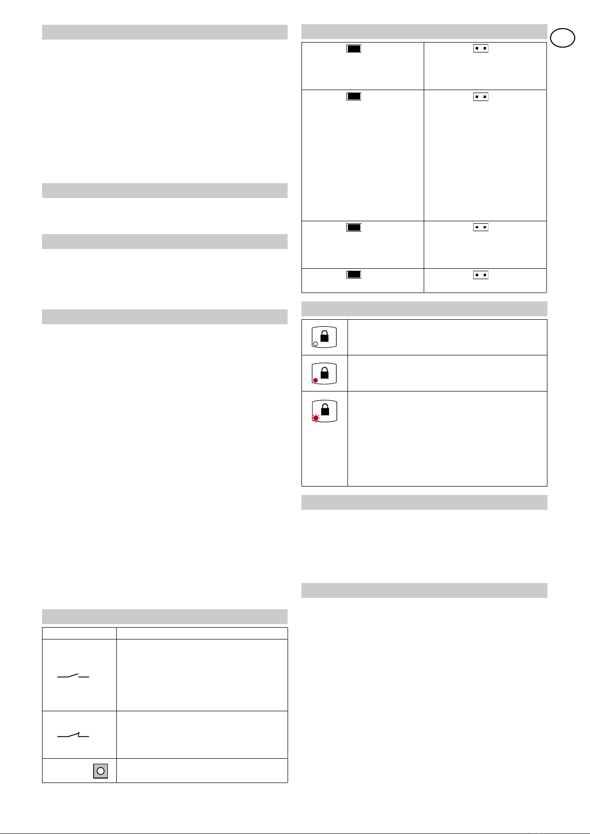
3.1 Commandes
Commande Description
1 OP
OPEN: permet d’ouvrir l’accès motorisé quelle que
soit la modalité de fonctionnement du sélecteur.
Remarque: si la modalité de fonctionnement
sélectionnée est STOP, la commande O PEN
active la séquence de fermeture nocturne
retardée.
1 KEY
KEY: en ouvrant le contact, le sélecteur est
désactivé.
Attention: si une commande (N.C.) est
connectée, enlever le shunt [P].
RESET RESET: supprime le code paramétré dans
le sélecteur.
3.2 Sélections
J1 = ON
Fermeture nocturne retardée
Durée de 10 s de la séquence
bidirectionnelle.
J1 = OFF
Fermeture nocturne retardée
Durée de 60 s de la séquence
bidirectionnelle.
J2 = ON
Ouverture normale
Commande OPEN à impul-
sion
J2 = OFF
Ouverture d’urgence
En maintenant enfoncée la
commande OPEN, le sélecteur
de fonctions est paramétré dans
la modalité porte ouverte.
Remarque: si la modalité de
fonctionnement sélectionnée
est STOP, la commande OPEN
active la séquence de fermeture
nocturne retardée.
J3 = ON
Activation code
Il est possible de paramétrer ou
de supprimer le code d’accès.
J3 = OFF
Désactivation code
Il n’est pas possible de paramétrer
ou de supprimer le code d’accès.
J4 = ON
Jack DMCS activé
J4 = OFF
Jack DMCS désactivé
3.3 Signalisations
LED ROUGE ÉTEINTE
- Le sélecteur est en état de marche et aucun code
d’accès n’est paramétré.
LED ROUGE ALLUMÉE
- Le sélecteur est protégé par un code d’accès.
- Le sélecteur est désactivé.
LED ROUGE CLIGNOTANTE
- Pendant les phases de paramétrage et de
suppression du code d’accès.
- Lors de l’allumage pendant la phase d’acquisition
du réseau (pendant 30 s).
- Le sélecteur ou un autre accès motorisé ne sont
pas reconnus par le réseau (éteindre et rallumer en
refaisant la phase d’acquisition).
3.4 Recepteur à rayons infrarouges TELRC
Il est possible d’effectuer le réglage à distance des paramètres
de l’armoire de commande (TC, R1, etc.) au moyen de la
télécommande TEL2, en installant le récepteur TELRC à
l’intérieur du sélecteur, comme indiqué dans le manuel du
récepteur TELRC.
4. FONCTIONNEMENT
Une fois les raccordements des sélecteurs et des armoires de
commande faits, alimenter tous les armoires de commande en
même temps et attendre 30 secondes.
Pendant la phase initiale d’apprentissage, la DEL rouge de la
touche cadenas clignote et les DEL vertes 1-2-3-4 s’allument
en fonction du nombre d’armoires de commande connectées en
réseau. Si les sélecteurs connectés en réseau sont au nombre
de deux, la DEL verte 6 s’allume.
Les modalités de fonctionnement sont indiquées dans le tableau
page 10.

10
COM E - IP1775
FMODALITÉS DE
FONCTIONNEMENT
SÉLECTEUR SANS
CODE
SÉLECTEUR AVEC
CODE
Unidirectionnelle touche 1 <CODE> + touche 1
Unidirectionnelle côté opposé
(LED clignotante) touche 1 pendant 3 s <CODE> + touche 1 pendant 3 s
Bidirectionnelle touche 2 <CODE> + touche 2
Ouverture partielle: seul pour unidirectionnelle
(touche 1) et bidirectionnelle (touche 2).
Remarque: si la porte a deux vantaux
battants, elle permet d’ouvrir un seul vantail.
touche 3 <CODE> + touche 3
Porte coulissante ouverte touche 4 <CODE> + touche 4
Porte à vantail battant ouverte touche 4 <CODE> + touche 4
Fermeture nocturne retardée (STOP).
Remarque: fait partir la séquence: bidi-
rectionnel (10 s avec J1=ON; 60 s avec
J1=OFF), porte fermée (max 60 s), STOP.
touche 5 <CODE> + touche 5
Fermeture nocturne immédiate (STOP) touche 5 pendant 3 s <CODE> + touche 5 pendant 3 s
Porte coulissante fermée touche 6 <CODE> + touche 6
Porte à vantail battant fermée touche 6 <CODE> + touche 6
Commande ouverture
touche cadenas + une des touches de 1 à 6 touche cadenas + <CODE>
RESET: annule toutes les données
acquises par l’armoire de commande
touches 1 et 5 ensemble <CODE> + touches 1 et 5 ensemble
Paramétrage code (avec J3=ON)
Remarque: le code est formé de 5 chiffres
au maximum. Pendant l’opération, la DEL
rouge clignote. touche cadenas + <CODE> + touche cadenas
pen. 3 s pen. 3 s
Suppression du code (avec J3=ON)
Remarque: pendant l’opération, la DEL
rouge clignote. touche cadenas + <CODE> + touche cadenas
pen. 3 s pen. 3 s
1
1
1
1
2
2
3
4
5
6
6
3
4
4
4
5
5
5
6
6
1
5
1
5
Touts droits reservés
Les informations mentionnées dans ce catalogue ont été controlées avec la plus grande attention. Toutefois, nous déclinons toute
responsabilité en cas d’erreurs, omissions ou approximations dépendant d’exigences techniques ou graphiques.

11 COM E - IP1775
D
ALLGEMEINE SICHERHEITSHINWEISE
Das vorliegende Installationshandbuch ist ausschliesslich für
Fachpersonal bestimmt. Vor Einbaubeginn sind die Anweisungen
sorgfältig durchzulesen. Falscher Einbau kann Gefahr mit sich
bringen. Das Verpackunsmaterial (Kunststoff, Polystyrol, usw.) ist
vorschriftsmäßig zu entsorgen. Es ist von Kindern fernzuhalten,
da es eine Gefahr für sie bedeutet. Vor Beginn der Montage ist
der einwandfreie Zustand des Produkts zu überprüfen. Bei Re-
paratur und Austausch sind ausschliesslich Originalersatzteile zu
verwenden. Die Hinweise sind sicher aufzubewahren und auch
allen weiteren Benutzern der Anlage zur Verfügung zu stellen.
1. TECHNISCHEN DATEN
Schutzgrad IP43;
Temperatur -20 °C / +55 °C
2. INSTALLATION
Befestigen Sie den Programmschalter in der Nähe des Antriebs in
einer sicheren und für den Gebrauch geeigneten Position.
Anm.: Die passende Unterputzdose gehört nicht zum Lieferumfang.
3. ELEKTRISCHE ANSCHLÜSSE
- Führen Sie die elektrischen Anschlüsse gemäß Abbildung 1 oder
2 aus.
Bei einer Entfernung zwischen Antrieb und Programmschalter
unter 5 m wird ein geschirmtes Kabel empfohlen, wenn
Störeinflüsse durch andere Kabel o. ä. nicht ausgeschlossen sind.
Bei Verwendung des mitgelieferten und an den Steckplatz COM
angeschlossenen Kabels [A] müssen die Klemmen 0-1-21-22
nicht an die Motorsteuerung angeschlossen werden.
- Mit einem einzigen Programmschalter können an zwei
Antrieben die gleichen Betriebsarten eingestellt werden. Nehmen
Sie hierzu die elektrischen Anschlüsse wie in Abb. 5 vor.
- Es können zwei Programmschalter an einen einzigen
Antrieb angeschlossen werden, siehe Abb. 6.
- Des weiteren können zur Einstellung der gleichen Betriebsarten
an bis zu vier (nicht redundanten) Antrieben ein oder zwei
Programmschalter angeschlossen werden, siehe Abb. 7.
Anm.: Verwenden Sie zur Vernetzung von Türantrieben immer ein
abgeschirmtes Kabel [F] für die Datenübertragung (nicht in unserem
Lieferangebot). Die Gesamtlänge darf 1000 m nicht überschreiten.
Soll der Programmschalter mehr als zwei Antriebe verwalten, trennen
Sie den Widerstand [X] auf der Motorsteuerung (Abb. 7) durch.
- Für den Zugang zum Anschluss des Antriebs an den Personal
Computer über die Software DMCS nehmen Sie die Abdeckung
des Programmschalter ab (DMCS Steckverbinder - Abb. 3). Die
Anweisungen im Software-Handbuch DMCS ermöglichen die
Überwachung und Steuerung des Antriebs vom Personal Computer aus.
3.1 Befehle
Befehl Beschreibung
1 OP
OPEN: Ermöglicht die Öffnung des Antriebs in
jeder Betriebsart des Programmschalters.
Anm.: ist die gewählte Betriebsart STOP,
startet der Befehl OPEN die Sequenz der
verzögerten Nachtschließung.
1 KEY
KEY: durch Öffnen des Kontakts wird der
Programmschalter deaktiviert.
Achtung: Beim Anschluss des Kontaktes
(N.C.) entfernen Sie die Brücke [P].
RESET RESET: löscht den im der Programmschalter
eingestellten Code.
3.2 Auswahl
J1 = ON
Verzögerte Nachtschließung
Verzögerungsdauer 15 Sek.
J1 = OFF
Verzögerte Nachtschließung
Verzögerungsdauer 60 Sek.
J2 = ON
Normal Öffnung bei
Impuls-Befehl OPEN
J2 = OFF
Not-Öffnung
Wird der Befehl OPEN
gedrückt gehalten, schaltet
der Programmschalter auf die
Funktion “Dauer-Auf”.
Anm.: ist die gewählte
Betriebsart STOP, startet der
Befehl OPEN die Sequenz der
verzögerten Nachtschließung.
J3 = ON
Code-Aktivierung
Der Zugangscode kann eingege-
ben oder gelöscht werden.
J3 = OFF
Code-Deaktivierung
Es kann kein Zugangscode
eingegeben oder gelöscht werden.
J4 = ON
Steckverbinder DMCS aktiviert
J4 = OFF
Steckverbinder DMCS deaktiviert
3.3 Anzeigen
ROTE LED AUSGESCHALTET
- Der Programmschalter ist in Betrieb. Es wurde
kein Zugangscode eingegeben.
ROTE LED DAUERLICHT
- Der Programmschalter ist durch einen
Zugangscode gesichert.
- Der Programmschalter ist deaktiviert.
ROTE LED BLINKLICHT
- Während des Eingabe- und Löschvorgangs des
Zugangscodes.
- Beim Einschalten während des Einlernvorgangs
für ca. 30 Sek.
- Der Programmschalter bzw. ein anderer Antrieb
werden vom Netz nicht erkannt (für ein neuerliches
Einlernen muss aus- und wieder eingeschaltet
werden).
3.4 Infrarot-Empfänger TELRC
Die Einstellungen der Motorsteuerung (TC, R1 usw.) kann per
Fernbedienung erfolgen. Hierzu muss der Empfänger TELRC
nach den Anweisungen des zugehörigen Handbuchs in den
Programmschalter eingebaut werden.
4. BETRIEB
Nach dem Anschluss der Wahlschalter und die Steuerung
gleichzeitig alle Steuerung speisen und 30 s warten.
Zu Beginn der Einlernphase blinkt die rote LED des
Vorhängeschlosstasters, und die grünen LED’s 1-2-3-4 schalten
sich entsprechend der Anzahl der vernetzten Steuerungen ein.
Sind zwei Programmschalter vernetzt worden, schaltet sich die
grüne LED 6 ein.
Die Betriebsarten sind in der Tabelle auf Seite 12 aufgeführt.

12
COM E - IP1775
DBETRIEBSARTEN PROGRAMMSCHALTER
OHNE CODE
PROGRAMMSCHALTER
MIT CODE
Einbahnverkehr Taste 1 <CODE> + Taste 1
Einbahnverkehr gegenüberliegende Seite
(LED Blinklicht) Taste 1 für 3 s <CODE> + Taste 1 für 3 s
Zwei Richtungen Taste 2 <CODE> + Taste 2
Teilöffnung
Anm.: bei zweiflügeligen Drehtoren ist nur
die Öffnung eines Flügels möglich.
Taste 3 <CODE> + Taste 3
Schiebetür daueroffen Taste 4 <CODE> + Taste 4
Drehtür Daueroffen Taste 4 <CODE> + Taste 4
Verzögerte Nachtschließung (STOP).
Anm.: startet die beidseitige Sequenz
(10 s mit J1=ON; 60 s mit J1=OFF), Tür
geschlossen (max 60 s), STOP.
Taste 5 <CODE> + Taste 5
Sofortige Nachtschließung (STOP) Taste 5 für 3 s <CODE> + Taste 5 für 3 s
Schiebetür zu Taste 6 <CODE> + Taste 6
Drehtür zu Taste 6 <CODE> + Taste 6
Befehl Öffnen
Vorhängeschloßtaste + Taste von 1 bis 6 Vorhängeschloßtaste + <CODE>
RESET: setzt die Motorsteuerung zurück
Tasten 1 und 5 gleichzeitig <CODE> + Taste 1 und 5 gleichzeitig
Code-Eingabe (mit J3=ON)
Anm.: der Code hat maximal 5 Stellen.
Während des Vorgangs blinkt die rote
LED. Vorhängesch. + <CODE> + Vorhängesch.
für 3 s für 3 s
Code-Löschung (mit J3=ON)
Anm.: während des Vorgangs blinkt die
rote LED. Vorhängesch. + <CODE> + Vorhängesch.
für 3 s für 3 s
1
1
1
1
2
2
3
4
5
6
6
3
4
4
4
5
5
5
6
6
1
5
1
5
Alle Rechte vorbehalten
Die wiedergegebenen Daten wurden mit höchster Sorgfalt zusammengestellt und überprüft. Es kann jedoch keinerlei Verantwor-
tung für eventuelle Fehler, Auslassungen oder Näherungen, die technischen oder graphischen Notwendigkeiten zuzuschreiben
sind, übernommen werden.

13 COM E - IP1775
E
ADVERTENCIAS GENERALES DE SEGURIDAD
El presente manual de instalaciòn està destinado exclusivamente
a professionales calificados. Leer atentamente las instrucciones
antes de comenzar la instalaciòn del producto. Una instalaciòn
incorrecta puede ser causa de peligro. El material de embalaje
(plàstico, poliestirol, etc.) debe desecharse sin causar daño al medio
ambiente y mantenerse fuera del alcance de los niños, porque es
una potencial fuente de peligro. Antes de comenzar la instalaciòn
verificar que el producto esté integro. Para cualquier reparaciòn o
sustituciòn del producto, utilizar exclusivamente repuestos originales.
Conservar estas instrucciones y entregarlas a futuros usuarios.
1. DATOS TECNICOS
Grado de protección IP43;
Temperatura -20 °C / +55 °C
2. INSTALACIÓN
Fijar el selector de funciones cerca de la automación en posición
segura y adecuada al uso.
Nota: Es posible fijar el selector de funciones empotrado en la
pared en cajas circulares, no suministrado por nosotros.
3. CONEXIONES ELÉCTRICAS
- Efectuar las conexiones eléctricas indicadas en fig. 1 o 2.
Hasta 5 m de distancia, y si no hay estorbos ambientales, no
es necesario emplear el cable blindado.
Si se usa el cable [A] en dotación, conectado al conector COM, no
se tienen que conectar los bornes 0-1-21-22 al cuadro electrónico.
- Con un único selector es posible configurar las mismas
modalidades de funcionamiento en dos automaciones,
efectuando las conexiones eléctricas indicadas en fig. 5.
- Es posible conectar dos selectores a una única automación,
como indicado en fig. 6.
- Además es posible conectar uno o dos selectores para
configurar las mismas modalidades de funcionamiento
hasta un máximo de cuatro automaciones (no redundantes),
como indicado en fig. 7.
Nota: para efectuar la conexión en red de los cuadros electrónicos,
usar un cable blindado [F] para transmisión datos (no suministrado
por nosotros), por una longitud máxima total de 1000 m. Cuando el
selector gestiona más de dos automaciones, cortar la resistencia
[X] presente en los cuadros electrónicos intermedios (fig. 7).
- La conexión de la automación al personal computer, mediante el
software DMCS, es accesible quitando la parte frontal del selector
(DMCS Jack - fig. 3). Siguiendo las indicaciones contenidas
en el manual del software DMCS, es posible monitorizar
y controlar la automación mediante el personal computer.
3.1 Mandos
Mando Descripción
1 OP
OPEN: Consiente abrir la automación en
cualquier modalidad de funcionamiento del
selector.
Nota: si la modalidad de funcionamiento
seleccionada es STOP, el mando OPEN inicia
la secuencia de cierre nocturno retrasado.
1 KEY
KEY: Abriendo el contacto, el selector se
deshabilita.
Atención: si se conecta un mando (N.C.),
quitar el conector puente [P].
RESET RESET: elimina el código configurado en
el selector.
3.2 Selecciones
J1 = ON
Cierre nocturno retrasado
Duración de 10 seg. de la
secuencia bidireccional.
J1 = OFF
Cierre nocturno retrasado.
Duración de 60 seg. de la
secuencia bidireccional.
J2 = ON
Apertura normal
Mando OPEN impulsivo
J2 = OFF
Apertura de emergencia
Manteniendo presionado el
mando OPEN, el selector de
funciones se configura en la
modalidad puerta abierta.
Nota: si la modalidad de fun-
cionamiento seleccionada es
STOP, el mando OPEN inicia
la secuencia de cierre nocturno
retrasado.
J3 = ON
Habilitación código
Es posible configurar o eliminar
el código de acceso.
J3 = OFF
Deshabilitación código
No es posible configurar o
eliminar el código de acceso.
J4 = ON
Jack DMCS habilitado
J4 = OFF
Jack DMCS deshabilitado
3.3 Señalizaciones
LED ROJO APAGADO
- El selector funciona y no está configurado ningún
código de acceso.
LED ROJO ENCENDIDO
- El selector está protegido por un código de
acceso.
- El selector está deshabilitado.
LED ROJO INTERMITENTE
- Durante las fases de configuración y eliminación
del código de acceso.
- Al encender, durante la fase de adquisición de la
red (por 30 seg.).
- El selector u otra automación, no son reconocidas
por la red (apagar y volver a encender volviendo a
hacer la fase de adquisición).
3.4 Receptor rayos infrarrojos TELRC
Es posible efectuar la regulación remota de las configuraciones
del cuadro electrónico (TC, R1, etc.) mediante el telemando TEL2,
instalando el receptor TELRC al interior del selector como indicado
en el manual del receptor TELRC.
4. FUNCIONAMIENTO
Después de haber realizado las conexiones de los selectores
y de los cuadros electrónicos, alimente simultáneamente todos
los cuadros electrónicos y espere 30 s.
Durante la fase inicial de aprendizaje el led rojo de la tecla
candado centellea y se encienden los led verdes 1-2-3-4 en
base al número de cuadros electrónicos conectados en red.
Si los selectores conectados en red son dos, se enciende el
led verde 6.
Las modalidades de funcionamiento están indicadas en la tabla
de página 14.

14
COM E - IP1775
EMODALIDAD DE
FUNCIONAMIENTO
SELECTOR
SIN CÓDIGO
SELETTORE CON
CODICE
Monodireccional tecla 1 <CÓDIGO> + tecla 1
Monodireccional lado opuesto
(led intermitente) tecla 1 por 3 seg <CÓDIGO> + tecla 1 por 3 seg
Bidireccional tecla 2 <CÓDIGO> + tecla 2
Apertura parcial: sólo monodireccional
(tecla 1) y bidireccional (tecla 2).
Nota: si la puerta tienen dos hojas batientes,
consiente la apertura de una sola hoja.
tecla 3 <CÓDIGO> + tecla 3
Puerta corredera abierta tecla 4 <CÓDIGO> + tecla 4
Puerta de hoja batiente abierta tecla 4 <CÓDIGO> + tecla 4
Cierre nocturno retardado (STOP).
Nota: pone en marcha la secuencia: bidi-
reccional (10 seg. con J1=ON; 60 seg. con
J1=OFF), puerta cerrada (máx. 60 seg.), STOP.
tecla 5 <CÓDIGO> + tecla 5
Cierre nocturno inmediato (STOP) tecla 5 por 3 seg <CÓDIGO> + tecla 5 por 3 seg
Puerta corredera cerrada tecla 6 <CÓDIGO> + tecla 6
Puerta de hoja batiente cerrada tecla 6 <CÓDIGO> + tecla 6
Mando abre
tecla candado + uno de las teclas de 1 a 6 tecla candado + <CÓDIGO>
POWER RESET: anula todos los datos
adquiridos por el cuadro electrónico
teclas 1 y 5 juntas <CÓDIGO> + teclas 1 y 5 juntas
Configuración código (con J3=ON)
Nota: el código está formato por un máximo
de 5 números. Durante la operación el led
rojo centellea. tecla candado + <CÓDIGO> + tecla candado
por 3 seg. por 3 seg.
Eliminación código (con J3=ON)
Nota: durante la operación el led rojo
centellea. tecla candado + <CÓDIGO> + tecla candado
por 3 seg. por 3 seg.
1
1
1
1
2
2
3
4
5
6
6
3
4
4
4
5
5
5
6
6
1
5
1
5
Todos los derechos son reservados
Los datos que se indican han sido redactados y controlados con la màxima atenciòn. Sin embargo no podemos asumir ninguna
responsabilidad por eventuales errores, omisiones o aproximaciones debidas a exigencias técnicas o gràficas.

15 COM E - IP1775
P
ADVERTÊNCIAS GERAIS PARA A SEGURANÇA
O presente manual de instalação é dirigido exclusivamente ao pessoal
profissionalmente competente. Ler atentamente as instruções antes
de iniciar a instalação do produto. Uma errada instalação pode ser
fonte de perigo. Os materiais da embalagem (plástico, polistireno,
etc.) não devem ser postos no ambiente e não devem ser deixados
ao alcance de crianças pois são potenciais fontes de perigo. Antes de
iniciar a instalação verificar a integridade do produto. Para a eventual
reparação ou a substituição dos produtos deverão ser utilizadas exclu-
sivamente peças de reposição genuínas. Estes instrução deve ser
mantida e deve ser remetida a todo possível usuário futuro do sistema.
1. CARACTERÍSTICAS TÉCNICAS
Grau de proteção IP43;
Temperatura -20 °C / +55 °C
2. INSTALAÇÃO
Fixar o selector de funções nas proximidades da automação
em posição segura e adequada ao uso.
N.B.: è possível fixar o selector de funções encaixado na parede
em caixas circulares, não de nosso fornecimento.
3. LIGAÇÕES ELÉCTRICAS
- Realizar as ligações eléctricas indicadas na fig. 1 ou então 2.
Até a 5 m de distância, e na ausência de distúrbios ambientais,
não é necessário utilizar o cabo revestido. Quando se usa o
cabo [A] fornecido pela fábrica, ligado ao conector COM, não se
devem ligar os bornes 0-1-21-22 ao quadro electrónico.
- Com um único selector é possível definir as mesmas
modalidades de funcionamento em duas automações,
realizando as ligações eléctricas indicadas na fig. 5.
- É possível ligar dois selectores numa única automação,
come indicado na fig. 6.
- Além disso, é possível ligar um ou dois selectores para definir
as mesmas modalidades de funcionamento até um máximo de
quatro automações (não redundantes), como indicado na fig. 7.
N.B.: para efectuar a ligação em rede dos quadros electrónicos,
utilizar um cabo revestido [F] para a transmissão dos dados (não
de nosso fornecimento), por um comprimento máximo total de
1000 m. Quando o selector controla mais de duas automações,
cortar a resistência [X] presente nos quadros electrónicos
intermédios (fig. 7).
- A ligação da automação ao “personal computer”, mediante
o software DMCS, é acessível retirando o painel frontal
do selector (DMCS Jack - fig. 3). Seguindo as indicações
contidas no manual do software DMCS, é possível monitorar
e controlar a automação mediante o “personal computer”.
3.1 Comandos
Comando Descrição
1 OP
OPEN: permite de abrir a automação em
qualquer modalidade de funcionamento do
selector.
N.B.: quando a modalidade de funcionamento
seleccionada é STOP, o comando OPEN
inicia a sequência de fecho nocturno atrasado.
1 KEY
KEY: ao abrir o contacto, o selector é
desactivado.
Atenção: quando se liga um comando
(N.C.), remover a ponte [P].
RESET RESET: elimina o código definido no
selector.
3.2 Selecções
J1 = ON
Fecho nocturno atrasado
Duração de 10 s da sequência
bidireccional.
J1 = OFF
Fecho nocturno atrasado
Duração de 60 s da sequência
bidireccional.
J2 = ON
Abertura normal
Comando OPEN impulsivo
J2 = OFF
Abertura de emergência
Mantendo carregado o comando
OPEN, o selector de funções é
definido na modalidade porta
aberta.
N.B.: quando a modalidade de
funcionamento seleccionada é
STOP, o comando OPEN inicia
a sequência de fecho nocturno
atrasado.
J3 = ON
Habilitação do código
É possível definir ou eliminar o
código de acesso.
J3 = OFF
Desabilitação do código
Não é possível definir ou
eliminar o código de acesso.
J4 = ON
Jack DMCS conectado
J4 = OFF
Jack DMCS desconectado
3.3 Sinalizações
LED VERMELHO APAGADO
- O selector está em função e não é definido
nenhum código de acesso.
LED VERMELHO ACESO
- O selector é protegido por um código de acesso.
- O selector é desconectado.
LED VERMELHO PISCANDO
- Durante as fases de definição e eliminação do
código de acesso.
- Ao acendimento durante a fase de aquisição da
rede (por 30 s).
- O selector ou então uma outra automação,
não são reconhecidos pela rede (apagar e ligar
novamente refazendo a fase de aquisição).
3.4 Receptor a raios infravermelhos TELRC
É possível efectuar a regulação remota das definições do quadro
electrónico (TC, R1, etc...) mediante o telecomando TEL2,
instalando o receptor TELRC dentro do selector como indicado
no manual do receptor TELRC.
4. FUNCIONAMENTO
Depois de ter efectuado as ligações dos selectores e dos
quadros electrónicos, alimentar contemporaneamente todos os
quadros electrónicos e esperar 30 s.
Durante a fase inicial de aprendizagem o led vermelho da tecla
cadeado pisca e se acendem os led verdes 1-2-3-4 em base
ao número de quadros electrónicos ligados na rede. Quando os
selectores ligados na rede são dois, acende o led verde 6.
As modalidades de funcionamento são indicadas na tabela da
página 16.

16
COM E - IP1775
PMODALIDADE DE
FUNCIONAMENTO
SELECTOR SEM
CÓDIGO
SELECTOR COM
CÓDIGO
Monodireccional tecla 1 <CÓDIGO> + tecla 1
Monodireccional lado oposto
(led piscando) tecla 1 por 3 s <CÓDIGO> + tecla 1 por 3 s
Bidireccional tecla 2 <CÓDIGO> + tecla 2
Abertura parcial: somente para mono-direc-
cional (tecla 1) e então bidireccional (tecla 2).
N.B.: quando a porta tem duas folhas ,
permite a abertura só de uma folha.
tecla 3 <CÓDIGO> + tecla 3
Porta de correr aberta tecla 4 <CÓDIGO> + tecla 4
Porta com folha aberta tecla 4 <CÓDIGO> + tecla 4
Fechadura nocturna de acção retardada
(STOP).
N.B.: executa a sequência: bidireccional
(10 s com J1=ON; 60 s com J1=OFF),
porta fechada (máx 60 s), STOP
tecla 5 <CÓDIGO> + tecla 5
Fecho nocturno imediato (STOP) tecla 5 por 3 s <CÓDIGO> + tecla 5 por 3 s
Porta de correr fechada tecla 6 <CÓDIGO> + tecla 6
Porta com folha fechada tecla 6 <CÓDIGO> + tecla 6
Comando abrir
tecla cadeado + uma das teclas de 1 a 6 tecla cadeado + <CÓDIGO>
POWER RESET: apaga todos os dados
adquiridos pelo quadro electrónico
teclas 1 e 5 juntas <CÓDIGO> + teclas 1 e 5 juntas
Definição do código (com J3=ON)
N.B.: o código é formado pelo máximo
de 5 números. Durante a operação o led
vermelho pisca. tecla cadeado + <CÓDIGO> + tecla cadeado
por 3 s por 3 s
Eliminação do código (com J3=ON)
N.B.: durante a operação o led vermelho
pisca. tecla cadeado + <CÓDIGO> + tecla cadeado
por 3 s por 3 s
1
1
1
1
2
2
3
4
5
6
6
3
4
4
4
5
5
5
6
6
1
5
1
5
Todos os direitos são reservados
Os dados indicados foram redigidos e controlados com o máximo cuidado. Contudo, não podemos assumir qualquer responsabilidade
por eventuais erros, omissões ou aproximações devidas a exigências técnicas ou gráficas.
Other manuals for COM E
1
Table of contents
Languages:
Popular Industrial Electrical manuals by other brands

Murata
Murata GRM2195C1H821JA01 Series Reference sheet

Murata
Murata GRM1555C1E4R2CA01 Series Reference sheet

HEIDENHAIN
HEIDENHAIN VT 121 operating instructions

Command access
Command access VLP-UL-M-KIT installation instructions

Lievers
Lievers LHF/HS-ER Operation manual

Elenco Electronics
Elenco Electronics RS-500 instruction manual