DIVERSITECH DD-3X4 Manual

Operation & Maintenance Manual
Industrial Downdraft Tables
DD-3X4, DD-3X6, DD-3X8
Single Workstation Tables
DD-4X4, DD-4X6, DD-4X8, DD-5X10
Multi Workstation Tables
READ AND SAVE THESE INSTRUCTIONS
Visit our Website for more information on this product
www.diversitech.ca
2500 Alphonse Gariepy, Montreal, Quebec H8T 3M2
OMM-DD-Industrial-Series-104[E N]

Table of Contents
SECTION 1 –SAFETY PRECAUTIONS OF FUME & DUST EXTRACTION/COLLECTION.................................................................................. 1
1.1 Symbols ................................................................................................................................................................................................. 1
1.2 User Responsibility................................................................................................................................................................................ 1
1.2 Fume Extraction Hazards ................................................................................................................................................................... 1
1.3 Dust Collection Hazards..................................................................................................................................................................... 1
SECTION 2 –SPECIFICATIONS .......................................................................................................................................................................... 2
2.1 Model Configurations & Description ............................................................................................................................................... 2
2.2 Product Specifications ....................................................................................................................................................................... 3
2.3 Filter Specifications ............................................................................................................................................................................. 3
2.4 Dimensions............................................................................................................................................................................................ 4
SECTION 3 –SETUP / INSTALLATION................................................................................................................................................................. 5
3.1 To Setup or Install Safely..................................................................................................................................................................... 5
3.2 Un-Packaging ...................................................................................................................................................................................... 5
3.3 Selecting a Location .......................................................................................................................................................................... 5
3.4 Installation............................................................................................................................................................................................. 5
3.5 Preparing Unit for Operation............................................................................................................................................................. 5
SECTION 4 –OPERATION .................................................................................................................................................................................. 6
4.1 To Operate Safely ............................................................................................................................................................................... 6
4.2 Controls................................................................................................................................................................................................. 6
4.3 Pre-Use Checklist ................................................................................................................................................................................. 6
4.4 Principles of Operation....................................................................................................................................................................... 6
4.5 Reverse Pulse Filter Cleaning System............................................................................................................................................... 7
SECTION 5 –MAINTENANCE & TROUBLESHOOTING .................................................................................................................................... 8
5.1 To Maintain this Product Safely......................................................................................................................................................... 8
5.2 Tools Required...................................................................................................................................................................................... 8
5.3 Routine Maintenance Schedule ...................................................................................................................................................... 9
5.4 Filter Replacement.............................................................................................................................................................................. 9
5.5 Troubleshooting Procedure ............................................................................................................................................................. 11
APPENDIX 1A –ELECTRICAL DIAGRAM [230/460/575v] 3-Phase Power ................................................................................................ 12
APPENDIX 2 –MAINTENANCE RECORD ....................................................................................................................................................... 13
APPENDIX 3 –REPLACEMENT PARTS............................................................................................................................................................. 14
APPENDIX 4 –TABLE OPTIONS ....................................................................................................................................................................... 15
Limited Equipment Warranty ....................................................................................................................................................... back cover
Freight Claims ............................................................................................................................................................................. back cover
Return Material Policy ............................................................................................................................................................... back cover
Page 1 of 17
SECTION 1 –SAFETY PRECAUTIONS OF FUME & DUST EXTRACTION/COLLECTION
READ
BEFORE
USE
This manual contains specific cautionary statements related to worker safety. To
protect yourself and others, read this manual thoroughly and follow as directed
before use. Not all hazards of fume & dust control are listed in this manual, and no
hazards related to welding, cutting, grinding, painting, deburring or other
applications are listed. Consult a qualified safety professional
DO
NOT
USE
Do not use this equipment:
To extract smoke or fumes above 180°F / 82°C.
To extract combustible dusts, liquid vapors, aggressive fumes such as acids.
If the power cord has been damaged or ground (third prong) removed.
Without a filter.
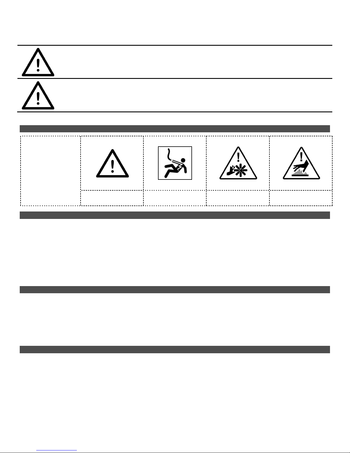
1.1 Symbols
This manual uses
several symbols to
highlight specific
hazards. Be familiar
with these symbols
and when you see
them in this manual,
read adjoining
warning text to avoid
the hazard.
WARNING!
DANGER!
ELECTRIC
SHOCK
MOVING
PARTS
HOT
PARTS
1.2 User Responsibility
Improper use can be hazardous.
It is your responsibility to follow all applicable ANSI, OSHA, UL, CSA, National & Local Fire Codes, and other
regulatory guidelines covering the safe use of equipment that extracts fumes, collects dusts, and exhausts filtered
air either indoors or outdoors.
Before use, inspect the unit for damage and verify it is working properly.
Only qualified persons should install, operate, maintain, or repair this unit.
Do not modify or repair the unit with parts or accessories not supplied by the manufacturer.
Consult filter manufacturer’s instructions for filter use and reuse, including instructions for cleaning.
1.2 Fume Extraction Hazards
Breathing smoke, fumes, or dusts produced in applications such as welding, cutting, grinding, painting, deburring
are hazardous to user’s health. Proper ventilation or use of well maintained fume extraction and/or dust collection
equipment helps the user avoid these hazards.
Breathable contaminants may not be visible or have an odor.
Stop operation and leave the area immediately if 1) breathing becomes difficult, 2) experience dizziness, 3)
impaired vision, 4) or eye/nose/mouth irritation.
1.3 Dust Collection Hazards
Dusts from many welding, cutting, grinding, painting, or deburring applications can be combustible.
Do not use or install equipment where any potential for combustible fumes or dusts are present, until a qualified
person has indicated it is safe to do so.
Never use or install equipment where the potential for combustible fumes or dusts are present without a
fire/explosion protection system.
If you are unsure if the product you purchased is correct for your application, call Diversi-Tech at 1-800-361-3733.

Page 2 of 17
SECTION 2 –SPECIFICATIONS
2.1 Model Configurations & Description
Open Works surface
Side/Back Walls
Clean Air Workstation
DD-3X4
DD-3X6
DD-3X8
DD-4X4
DD-4X6
DD-4X8
DD-5X10
Page 3 of 17
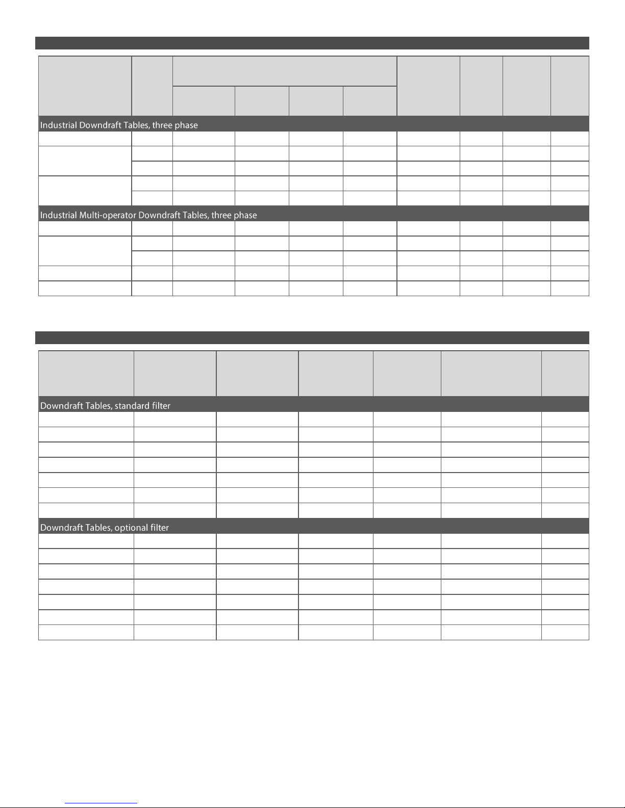
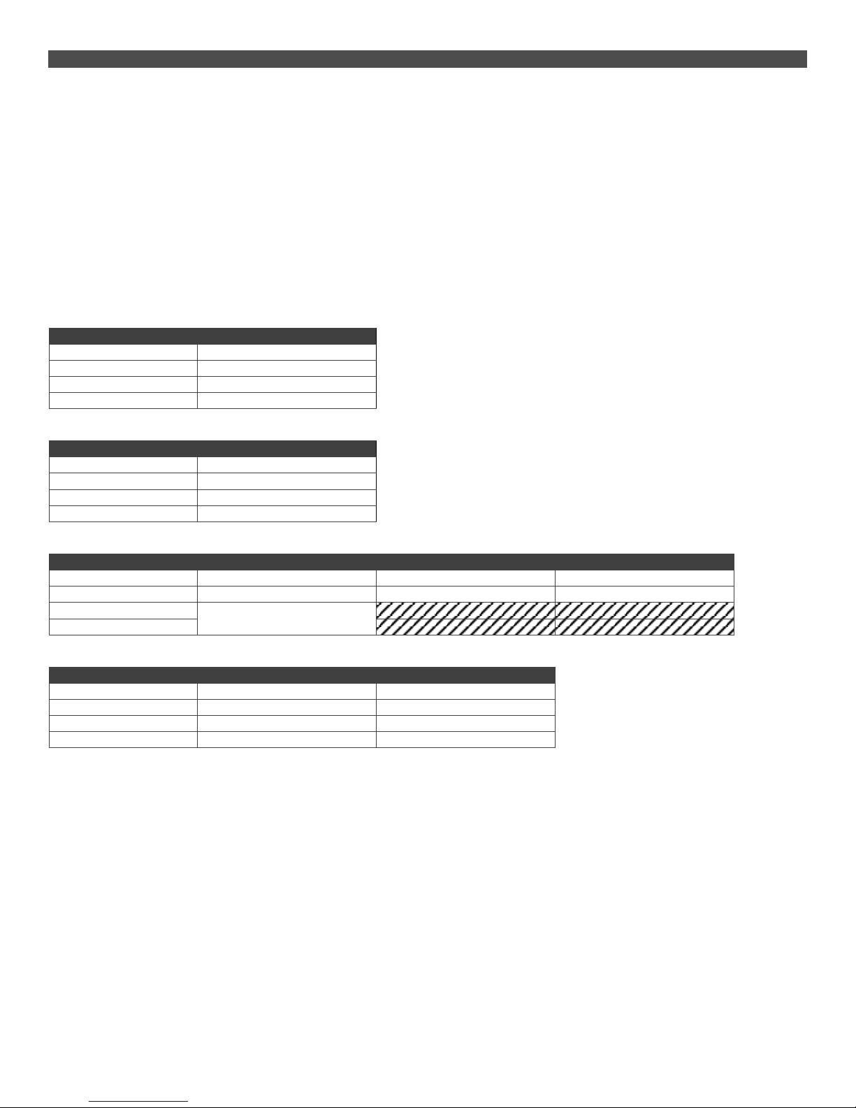
2.2 Product Specifications
2.3 Filter Specifications
For information on inspecting and cleaning filter, or purchasing replacement filters, contact DiversiTech at 1-800-361-3733.
Avg.
Avg. Airflow Static Face Noise
Motor Phase @230V @460V @575V Pressure Pressure Velocity @5ft.
(H.P.) (hz) (amps) (amps) (amps) (CFM) (in.) (FPM) (dB)
DD-3X4 5.0 3P / 60Hz 12.0 5.8 4.6 4300 4.0 450 79
5.0 3P / 60Hz 12.0 5.8 4.6 4300 4.0 325 79
7.5 3P / 60Hz 17.2 8.6 7.0 4800 4.0 375 81
7.5 3P / 60Hz 17.2 8.6 7.0 4800 4.0 330 81
10.0 3P / 60Hz 24.0 12.0 9.6 5050 4.0 380 83
DD-4X4 5.0 3P / 60Hz 22.0 11.0 9.0 4300 4.0 425 79
7.5 3P / 60Hz 15.2 7.6 6.1 4800 4.0 325 79
10.0 3P / 60Hz 24.0 12.0 9.6 5050 4.0 375 85
DD-4X8 10.0 3P / 60Hz 24.0 12.0 9.6 5050 4.0 300 81
DD-5X10 15.0 3P / 60Hz 42.0 21.0 17.0 8600 4.0 330 81
Model
Power
DD-3X8
DD-3X6
DD-4X6
Filter Part Filter Filter Filter Qty.
Type Number Size Area Efficiency Filters
(sq. ft.) Required
DD-3X4 Nanofiber S-3X4-0024 16" w/flange 140 99.99% @ 0.5 micron 2
DD-3X6 Nanofiber S-3X6-0024 16" w/flange 140 99.99% @ 0.5 micron 2
DD-3X8 Nanofiber S-3X8-0024 16" w/flange 140 99.99% @ 0.5 micron 4
DD-4X4 Nanofiber S-4X4-0024 16" w/flange 140 99.99% @ 0.5 micron 2
DD-4X6 Nanofiber S-4X6-0024 16" w/flange 140 99.99% @ 0.5 micron 2
DD-4X8 Nanofiber S-4X8-0024 16" w/flange 140 99.99% @ 0.5 micron 4
DD-5X10 Nanofiber S-5X10-0024 16" w/flange 140 99.99% @ 0.5 micron 6
DD-3X4 Spunbond Poly S-3X4-0002 16" w/flange 55 99.7% @ 0.5 micron 2
DD-3X6 Spunbond Poly S-3X6-0002 16" w/flange 55 99.7% @ 0.5 micron 2
DD-3X8 Spunbond Poly S-3X8-0002 16" w/flange 55 99.7% @ 0.5 micron 4
DD-4X4 Spunbond Poly S-4X4-0002 16" w/flange 55 99.7% @ 0.5 micron 2
DD-4X6 Spunbond Poly S-4X6-0002 16" w/flange 55 99.7% @ 0.5 micron 2
DD-4X8 Spunbond Poly S-4X8-0002 16" w/flange 55 99.7% @ 0.5 micron 4
DD-5X10 Spunbond Poly S-5X10-0002 16" w/flange 55 99.7% @ 0.5 micron 6
Model
Page 4 of 17
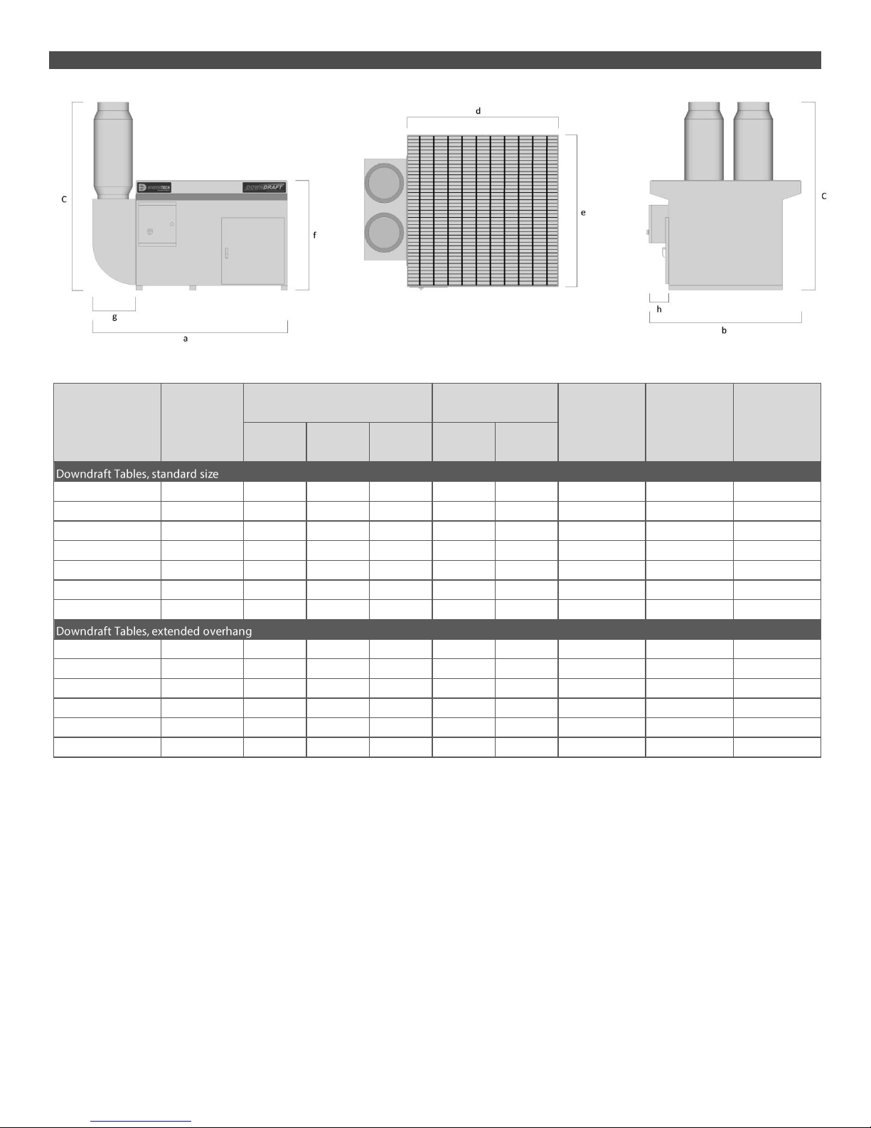
2.4 Dimensions
Exhaust Table
Diameter Width Height Length Width Length Height Exhaust
(in.) [a] [C ] [b] [d] [e] [f] [g] [h]
DD-3X4 10" x 2 49 68.5 43 48 42 36 14 6"
DD-3X6 10" x 2 73 68.5 43 72 42 36 14 6"
DD-3X8 10" x 2 97 68.5 43 96 42 36 14 6"
DD-4X4 10" x 2 49 68.5 49 48 48 36 14 6" x 2
DD-4X6 10" x 2 73 68.5 49 72 48 36 14 6" x 2
DD-4X8 10" x 2 97 68.5 49 96 48 36 14 6" x 2
DD-5X10 10" x 2 121 68.5 31 120 30 36 34 12" x 2
DD-3X4-EO 10" x 2 49 68.5 49 48 48 36 14 12"
DD-3X6-EO 10" x 2 73 68.5 49 72 48 36 14 12"
DD-3X8-EO 10" x 2 97 68.5 49 96 48 36 14 12"
DD-4X4-EO 10" x 2 49 68.5 61 48 60 36 14 12" x 2
DD-4X6-EO 10" x 2 73 68.5 61 72 60 36 14 12" x 2
DD-4X8-EO 10" x 2 97 68.5 61 96 60 36 14 12" x 2
Model
Overhang
Footprint (in.)
Worksurface (in.)

Page 5 of 17
SECTION 3 –SETUP / INSTALLATION
3.1 To Setup or Install Safely
Do not place unit near flammables or combustible surfaces.
Refer to SECTION 2: Specifications, to know the electrical requirements of the unit you are
installing and ensure adequate input power that is properly sized, rated, and protected.
This unit must be grounded for safe operation.
3.2 Un-Packaging
1. Immediately upon receiving the unit, carefully examine the carton for damage during transit.
2. Remove packing material.
3. Avoid tipping or inverting during handling.
4. The item serial number, model, and electrical ratings are listed on the nameplate. Record this information in the
Maintenance Record provided on page 10, or your own preventative maintenance system.
3.3 Selecting a Location
Choose a location where the unit will be used, near the operator.
Choose a location sufficiently close to a grounded power source.
3.4 Installation
Electrical Connection:
oThis unit requires 3-phase (230/460/575V) direct connection.
oSee APPENDIX 1: Electrical Diagram for wiring instructions.
oHave a certified electrician install electrical connection according to local regulations.
oAll three power leads must be connected to L1, L2 and L3 on the contactor.
oThis unit must be grounded for safe operation.
oIf on start-up the downdraft table seems to be lacking performance or the table sounds very loud, the
motor is most likely running in the reverse direction. Reversing leads L1 and L3 will reverse motor rotation in
the right direction.
oCorrect direction of BLOWER WHEEL ROTATION = CLOCKWISE
Compressed Air:
oSupply 80-90 PSI of CLEAN, DRY, compressed air to the bulkhead bushing on the side of the unit.
oThe air tank in the downdraft table is fabricated to allow a maximum of 90 PSI, DO NOT attempt supplying
air pressure greater than 90 PSI without a properly installed pressure regulator.
oMoisture in airline can damage filter(s); use an air dryer if required.
Special Installation steps for table options:
oPlasma Cutting Packages & Kits
oSpray Painting Packages & Kits
3.5 Preparing Unit for Operation
Remove all packaging and shipping protection before use, in accordance with SECTION 3.2: Un-Packaging
Select a location appropriate for use that complies with all safety instructions contained herein, and SECTION 3.3:
Selecting a Location.
Confirm installation of correct input power source, compressed air, and any special installation requirements, in
accordance with SECTION 3.3: Installation. Look at the manufacturer’s label located on the exterior of the unit and
ensure the source is correctly sized in terms of Voltage and Amperes.
Prior to use in your application, turn the unit ON, and perform a function test. To do so:
oTurn switch to ON position
oLOOK: Is the unit level, stable, and that nothing is obstructing the extraction path.
oLISTEN: Does the motor and suction sound smooth and within expected volumes.
oFEEL: Place your hand on top of the unit and sense for unexpected vibration. Place you hand in front of
the intake surface and sense for expected level(s) of suction.
Inform all potential users of this equipment where they may find and review this manual.
Page 6 of 17
SECTION 4 –OPERATION
4.1 To Operate Safely
Read and understand SECTION 1: Safety Precautions and SECTION 4: Operation before use
Read and understand all Material Safety Data Sheets and Manufacturer’s instructions of all
process materials, consumables, and equipment used in conjunction with this equipment.
Keep away from all mechanical moving parts including motor, gears, and other pinch points.
Do not use product without first confirming if a Spark Arrestor is required and installed for the type
of dust, or fumes you are extracting and/or collection. If you are unsure, call a DiversiTech
representative at 1-800-361-3733.
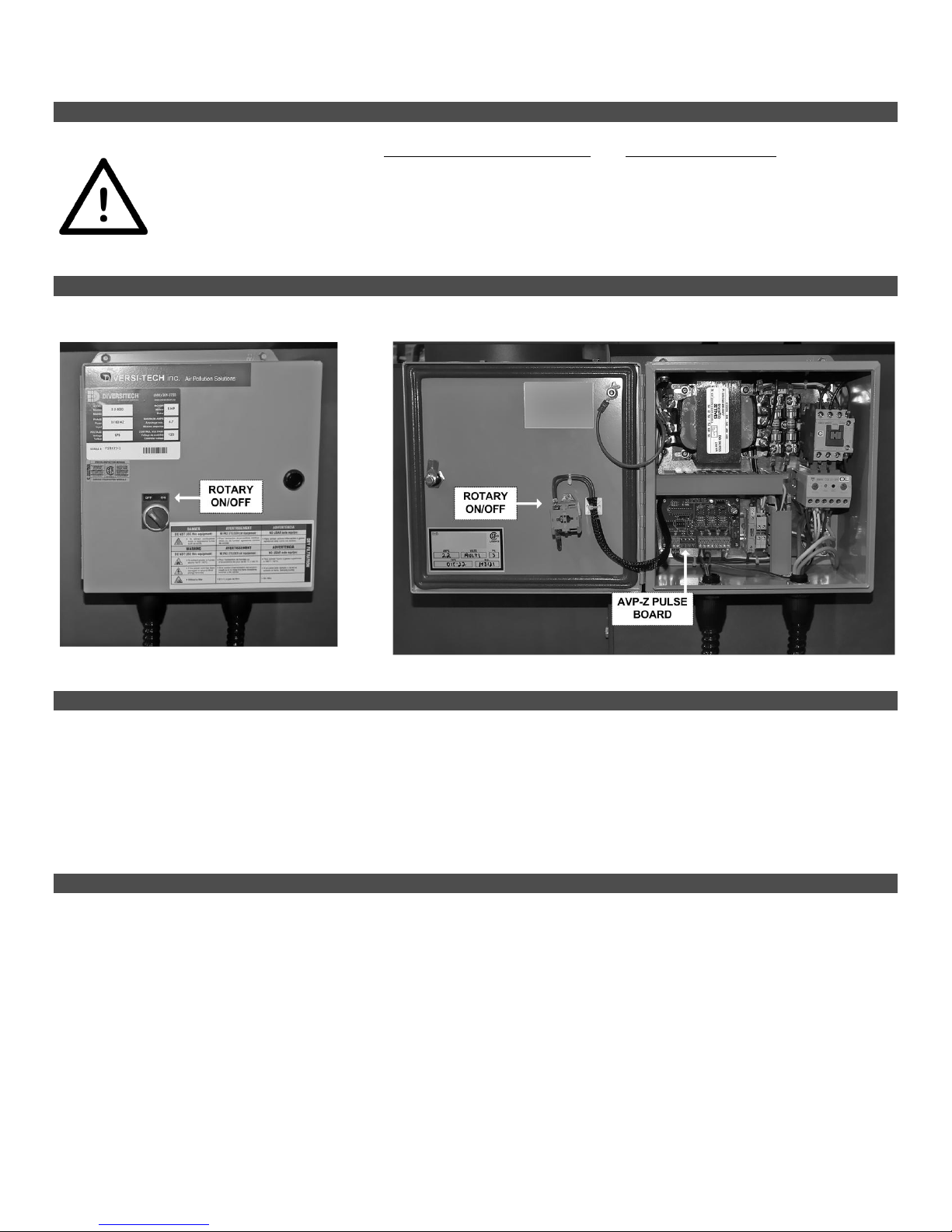
4.2 Controls
4.3 Pre-Use Checklist
Prior to use in your application, turn the unit ON, and perform a function test. To do so:
oTurn switch to ON position
oLOOK: Is the unit level, stable, and that nothing is obstructing the extraction path.
oLISTEN: Does the motor and suction sound smooth and within expected volumes.
oFEEL: Place your hand on top of the unit and sense for unexpected vibration. Place you hand in front of
the intake surface and sense for expected level(s) of suction.
Inform all potential users of this equipment where they may find and review this manual.
4.4 Principles of Operation
This product is designed to capture and clean smoke and dust from medium & heavy duty welding, soldering, and grinding
applications. When operating, air is drawn in through the table surface grating, passes through spark-arrestor baffling, then
through the table’s filtration system, and exhausted through the side stack exhaust.
This product consists of basic components:
1. Protective table surface grating(s)
2. Multi-stage spark-Arrestance baffling
3. Table cabinet/module(s)
4. Cartridge Filter(s)
5. Motor/Blower Assembly
6. Reverse pulse filter cleaning system
7. Dust Drawer
Page 7 of 17
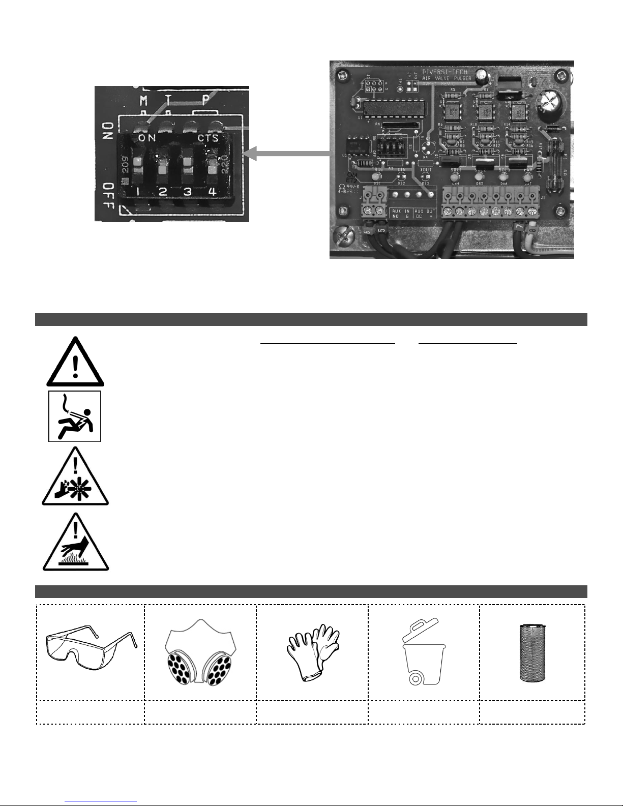
4.5 Reverse Pulse Filter Cleaning System
The downdraft table is equipped with a reverse pulse automatic filter cleaning system. This system is controlled by a PC
board inside the control box (Labelled “AVP-Z”). Changing the dip switch settings on the AVP-Z board, allows you to
control:
1. Pulsing online or offline
2. Number of pulses
3. Pulse duration
Solenoid operated air valves discharge large blasts of air through the filter cartridges thus dislodging particles embedded in
the filter media. The particles fall into a dust drawer located below the cartridge. The angled v-shaped baffles above the
drawer prevent the dust from re-entering the cabinet when the machine is turned on.
Neglecting to pulse the filter regularly will reduce filter life.
Factory Setting
DIP SWITCH #
FACTORY SETTING
This factory setting allows for online & offline
pulsing. 1 x 0.5 second air blast every 45 seconds,
while online, and 20 x 0.5 second air blast when
offline.
1
ON
2
OFF
3
ON
4
OFF
Recommended for Aluminum Dust
DIP SWITCH #
FACTORY SETTING
This factory setting allows for only offline pulsing,
20 x 0.5 second air blast each time the machine is
switched off.
1
OFF
2
OFF
3
ON
4
OFF
Custom Application Settings
DIP SWITCH #
PURPOSE
LEFT
RIGHT
1
Mode
Online & Offline
Offline Only
2
Duration
0.5 second
1 second
3
Number of Pulses
4
# OF PULSES
DIP SWITCH #3
DIP SWITCH #4
5
OFF
OFF
10
OFF
ON
20
ON
OFF
30
ON
ON
Page 8 of 17
AVP-Z Board
SECTION 5 –MAINTENANCE & TROUBLESHOOTING
5.1 To Maintain this Product Safely
Read and understand SECTION 1: Safety Precautions and SECTION 4: Operation before
maintenance.
Do not breathe the dust collected from product while changing/cleaning filters or performing
maintenance on this product.
Disconnect power before performing any maintenance on unit, including filter inspection. The
input power to this unit is high voltage, and touching any live electrical parts can cause fatal
shocks or severe burns. Do not touch live electrical parts.
Keep away from all mechanical moving parts including motor, gears, and other pinch points
while operating.
Operating this unit causes some parts to heat to a point that will burn bare hands. Before
maintenance allow parts to cool, or use proper tools and personal protection equipment during
maintenance.
5.2 Tools Required
EYE
PROTECTION
RESPIRATOR
GLOVES
WASTE CONTAINER
REPLACEMENT FILTER
(if required)
Page 9 of 17
5.3 Routine Maintenance Schedule
The manufacturer recommends the following routine maintenance based on light-duty use in normal operating conditions.
Service more frequently if the unit is used in severe conditions.
Frequency
Manual Reference
Pre-Use
Perform pre-use inspection to ensure operating correctly.
If you application involves grinding, or any process that produces heat/sparks –lift the top
grate and visually confirm that metal-mesh pre-filters (spark arrestors) are correctly seated
on the baffle tray, and that no holes are present.
4.3
Every (1) Week or 20 Operating Hours - Empty Dust Drawer/Clean Surface
Remove and wipe clean surface matting (if used). Remove dust drawer and deposit
accumulated particulate in appropriate waste container. Refer to local regulations
regarding disposal procedures as some captured contaminants may be flammable,
explosive, or toxic.
Particles and stray material on the surface should be blown into the table towards the filter
using compressed air. If a cushion grid mat (option) is used, direct particles into the table
using a broom or brush.
Recommended frequency is one week, but may be less or more depending of application.
Every (4) Week or 80 Operating Hours –Inspect/Clean Cabinet
Remove and wipe down dust drawer, baffle trays, and metal mesh prefilters, depositing
accumulated particulate in appropriate waste container. Refer to local regulations
regarding disposal procedures as some captured contaminants may be flammable,
explosive, or toxic.
Inspect, and clean if necessary the cabinet interior and dust drawer slats.
As Required –Replace Filter
1. Replace Filter , see SECTION 5.4: Filter Replacement for instruction
Every (12) months Inspect Basic Components
1. Clean unreadable labels and exterior surfaces
2. Cabinet: Look for loose wiring.
5.4 Filter Replacement
Warning
Do not attempt to clean filters containing hazardous materials; refer to local regulations
regarding disposal procedures as some captured contaminants may be flammable, explosive,
or toxic.
Cleaning cartridge filters with compressed air, water, or solvents can damage/destroy the filter
media. Always check the manufacturer’s instructions and specifications prior to cleaning.
Nanofiber / Paper-pleated filters
Do not wet or clean the cartridge with any liquid, as it may cause the forming of unwanted
blockage on the filter media.
Spunbond-poly filters
Cleaning should be carried out on water-soluble materials only.
Hydrocarbons may not be removable.
The use of solvents may attack certain components of the filter. Consult the instructions and
specifications prior to cleaning.

Page 10 of 17
The table’s reverse-pulse filter system works to extend the life expectancy of your filter(s). The actual usable life of the filter
varies greatly on application,
density, particle size, humidity, oil, but the typical range when pulsed regularly is 6-18 months.
As part of routine maintenance, it is important to visually inspect the filter. Replace the filter if you see:
1.
Overloading or accumulation of particles
2.
Rips, tears, or warping of filter media
3.
Decreased table performance due to excessive static build up
To remove the filter, follow this 3-step procedure:
1. Open the cabinet door
2. Unhook barrel bolt latch
3. Slide filter cartridge(s) out
Page 11 of 17
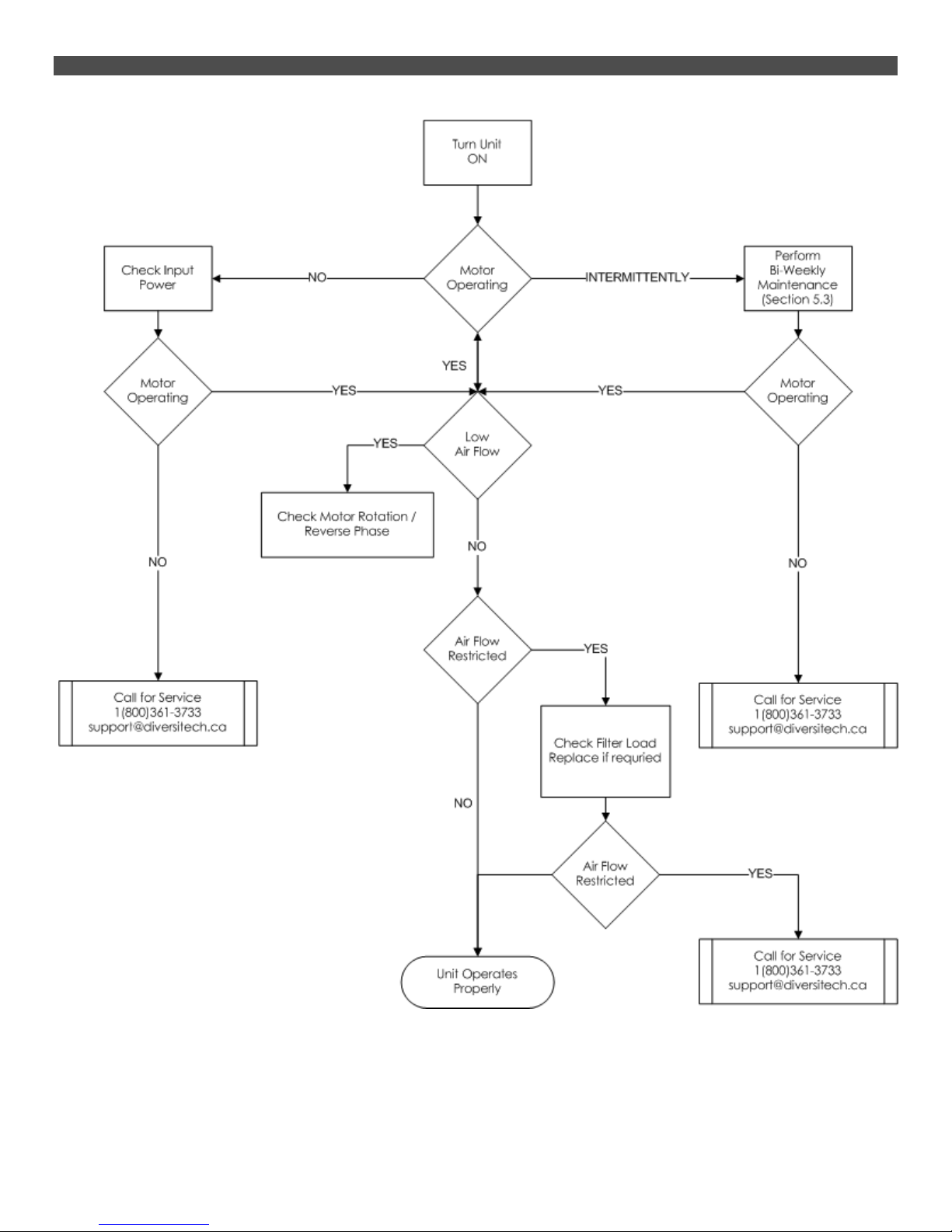
5.5 Troubleshooting Procedure

Page 12 of 17
APPENDIX 1A –ELECTRICAL DIAGRAM [230/460/575v] 3-Phase Power
ELECTRIC
SHOCK
HAZARD
Disconnect power before performing any maintenance on unit, including filter
inspection. The input power to this unit is high voltage, and touching any live
electrical parts can cause fatal shocks or severe burns. Do not touch live electrical
parts.

Page 13 of 17
APPENDIX 2 –MAINTENANCE RECORD
DiversiTech Inc. authorizes this page to be photocopied or otherwise reproduced as needed for management of
maintenance records.
MANUFACTURER:
DIVERSITECH INC.
MODEL NO:
FRED
SERIAL NO:
SERVICE LOCATION:
CONTROL NO:
Date
Description of Service
Serviced By
Location
Comments
Only use manufacturer approved replacement parts on this unit.

Page 14 of 17
APPENDIX 3 –REPLACEMENT PARTS
Industrial Downdraft Tables (dry)
ITEM NUM B ER D ESC RIP TION
S-DXD-0907 3/4" Air Valve, DD ●●●●●●●
S-DXD-0808 12V SOLINOID VALVE ●●●●●●●
S-DXD-0106 AVP-Z pulse cleaning control board ●●●●●●●
S-C ONE-0074 5.0HP Motor C one, plastic ● ● ●
S-C ONE-0063 7.5/10HP Motor Cone, steel ● ● ● ●
S-C ONE-0064 #N/A ●
S-WHEL-0003 5.0HP C omposite Blower Wheel, backward inclined ● ● ●
S-WHEL-0010 7.5HP Aluminum Blower Wheel, backward inclined ● ● ●
S-WHEL-0011 10.0HP Aluminum Blower Wheel, backward inclined ● ● ●
S-WHEL-0012 15.0HP Aluminum Blower Wheel, backward inclined ●
S-184T-050T2 5.0HP TEFC MOTOR [230/3/60] ● ● ●
S-184T-050T4 5.0HP TEFC MOTOR [460/3/60] ● ● ●
S-184T-050T5 5.0HP TEFC MOTOR [575/3/60] ● ● ●
S-213T-075T2 7.5HP TEFC MOTOR [230/3/60] ● ● ●
S-213T-075T4 7.5HP TEFC MOTOR [460/3/60] ● ● ●
S-213T-075T5 7.5HP TEFC MOTOR [575/3/60] ● ● ●
S-215T-100T2 10.0HP TEFC Motor [230/3/60] ● ● ●
S-215T-100T4 10.0HP TEFC Motor [460/3/60] ● ● ●
S-215T-100T5 10.0HP TEFC Motor [575/3/60] ● ● ●
S-254T-150T2 15.0HP TEFC Motor [230/3/60] ●
S-254T-150T4 15.0HP TEFC Motor [460/3/60] ●
S-254T-150T5 15.0HP TEFC Motor [575/3/60] ●
DD-5X10
DD-3X4
DD-3X6
DD-3X8
DD-4X4
DD-4X6
DD-4X8

Page 15 of 17
APPENDIX 4 –TABLE OPTIONS
1. When ordering, please replace #X# with table size.
Part # Description
DD-3X4
DD-3X6
DD-3X8
DD-4X4
DD-4X6
DD-4X8
DD-5X10
A-#X#-SBW-01 Side & back walls, powder coated mild steel ● ● ● ●
A-#X#-SBW-02 Hinged right side & fixed back/left side walls, powder coated mild steel ● ● ●
A-#X#-SBW-04 Hinged left/right side walls & fixed back wall, powder coated mild steel ● ● ●
A-#X#-SBW-11 Side & back walls, 4" steel frame with clear lexan insert ● ● ●
A-#X#-SBW-12 Hinged right wall & fixed back/left walls, 4" steel frame w/ clear lexan insert ● ● ●
A-#X#-SBW-14 Hinged left/right side walls & fixed back, 4" steel frame w/ clear lexan insert ● ● ●
A-#X#-SMW-01 Side walls & middle seperator, powder coated mild steel ● ● ● ●
A-#X#-SMW-11 Side walls & middle seperator, 4" steel frame with clear lexan insert ● ● ● ●
O-#X#-LK-24F 24" Dust & Vapor Proof Flourescent Light Kit ●●●
O-#X#-LK-48F 48" Dust & Vapor Proof Flourescent Light Kit ● ● ●● ●● ●●
O-#X#-BDH Backdraft hood w/sliding gates ● ● ●
O-#X#-XA Extractor Arm w/bracket, flexhose, and blast gate (6" x 10') ●●●●●●●
O-#X#-MH Minihelic gauge ●●●●●●●
O-#X#-SC 3" Swivel castors, set ●●●●●●●
O-#X#-MR Mirror table ●●●●●●●
AK-#X#-ODOR Odor Kit Adds: V-bank module w/ A40 activated carbon granules ● ● ● ● ● ●
AK-#X#-SSH Kit adds: Side stack silencer w/HEPA filter and frame ●●●●●●●
A-#X#-OPT Set of two Opti-flow grates for ●●●●●●●
A-#X#-CGM-B Blue cushion grid matting ●●●●●●●
A-#X#-GL Grounding lug ●●●●●●●

Page 16 of 17
NOTES

Page 17 of 17
NOTES

Limited Equipment Warranty
All Diversi-Tech units are warranted to be free from defects in material for a
period of two years from the date of purchase. Diversi-Tech Inc. will repair, at
our option, any defective parts returned to the manufacturer’s plant in
Montreal - Quebec freight prepaid- which fail during the warranty period.
This warranty is limited to replacement parts ONLY, subject to on site or in
house evaluation of defective materials and does not apply to any personal
liability or property loss that occurs due to the use or installation of this
equipment.
FREIGHT CLAIMS
All Diversi-Tech units are sold ex-plant, Montreal, Qc., Canada. Therefore, it is
the user’s responsibility to file any freight claims for obvious or concealed
damages which developed in transit from Montreal to your location or when
drop shipped.
RETURN MATERIAL POLICY
Prior to the return of material, for whatever reason, a return manufacturing
authorization number (RMA#) is required from the Diversi-Tech production
control department. This procedure is necessary for proper control and
handling of returned materials. Fax us or call to obtain the RMA.
All material must be returned prepaid. Credit will be given for returns for
warranty replacement. Freight collect shipments will not be accepted. It is
the shipper’s responsibility to insure that material being returned to Diversi-
Tech is adequately packaged for shipment to preclude damages.
2500 Alphonse Gariepy
Montreal, Quebec
H8T 3M2
Visit our Website for more information of this product
www.diversitech.ca
Tel: 1.800.361.3733
Fax: 1.514.631.9480
This manual suits for next models
6
Table of contents
Other DIVERSITECH Indoor Furnishing manuals

Popular Indoor Furnishing manuals by other brands

Home Styles
Home Styles 88502395 C quick start guide

Simpli Home
Simpli Home WyndenHall Brooklyn+Max AXCRAMH20-HIC manual

m-Dimension
m-Dimension 1508 Assembly instructions

GFW
GFW NORDICA STUDY DESK Assembly instructions

home star
home star MAINSTAYS 109078 Assembly instructions

Seconique
Seconique Panama 1 Assembly instructions


Rauch
Rauch M2227 Assembly instructions

BUT
BUT LEEDS 3 4894223206396 Assembly instructions

Naterial
Naterial MOBIS TRAY 3276007268072 Assemby - Use - Maintenance Manual

ducduc
ducduc OSLO Assembly instructions

Vinsetto
Vinsetto 921-451 Assembly & instruction manual

Crate&Barrel
Crate&Barrel Alfresco II instructions