Dixon Bayco FloTech FT208 User manual

FloTech
FT208
CheckMate
Programmable
Retain / Overfill
Onboard Monitor
Dixon Bayco
FloTech Division
Cincinnati, Ohio

FloTech Programmable CheckMate Retain / Overfill Monitor
Page 2 REV G FT208 CheckMate

FloTech Programmable CheckMate Retain / Overfill Monitor
FT208 CheckMate REV G Page 3
Table of Contents
Introduction..................................................................................... 4
Monitor Features............................................................................. 4
Monitor Indicators .......................................................................... 5
Monitor Connections ...................................................................... 5
Mounting Instructions..................................................................... 6
Monitor Housing......................................................................... 6
Cable Installation Instructions ........................................................ 6
Monitor Housing......................................................................... 7
Wiring Instructions ......................................................................... 8
Proper Wire Connections............................................................ 8
Monitor Wiring Connections...................................................... 9
TB1 POWER Connections ................................................... 10
TB2 TOP and BOTTOM SENSOR Connections................. 10
TB4 AUX PERMIT Connections......................................... 11
TB5 PROGRAM Connections.............................................. 14
FLOAT, THERMISTOR and OPTIC Rack Connections..... 11
Programming................................................................................. 14
Overview................................................................................... 14
Procedure .................................................................................. 15
Operation....................................................................................... 16
Normal Operation ..................................................................... 16
Troubleshooting............................................................................ 18
Technical Support Hotline............................................................ 22
FloTech Programmable CheckMate Retain / Overfill Monitor
Page 4 REV G FT208 CheckMate
Introduction
This Manual describes the features, installation, programming,
operation and troubleshooting techniques for the FloTech FT208
CheckMate Programmable Retain / Overfill Onboard Monitor.
Monitor Features
The FloTech FT208 CheckMate Retain / Overfill Monitor has the
following features:
-Operates on 12 VDC or 24 VDC systems.
-Monitors up to eight overfill sensors.
-Monitors up to eight retain sensors.
-Top Only or Top and Bottom configuration.
-Connects to Float, Thermistor or Optic style rack
connections.
-Non I.S. Relay Output
-The monitor is field programmable.
-Simple Wiring –no jumpers, terminators or dummies
required
-Compatible with Two Wire or Five Wire type sensors.
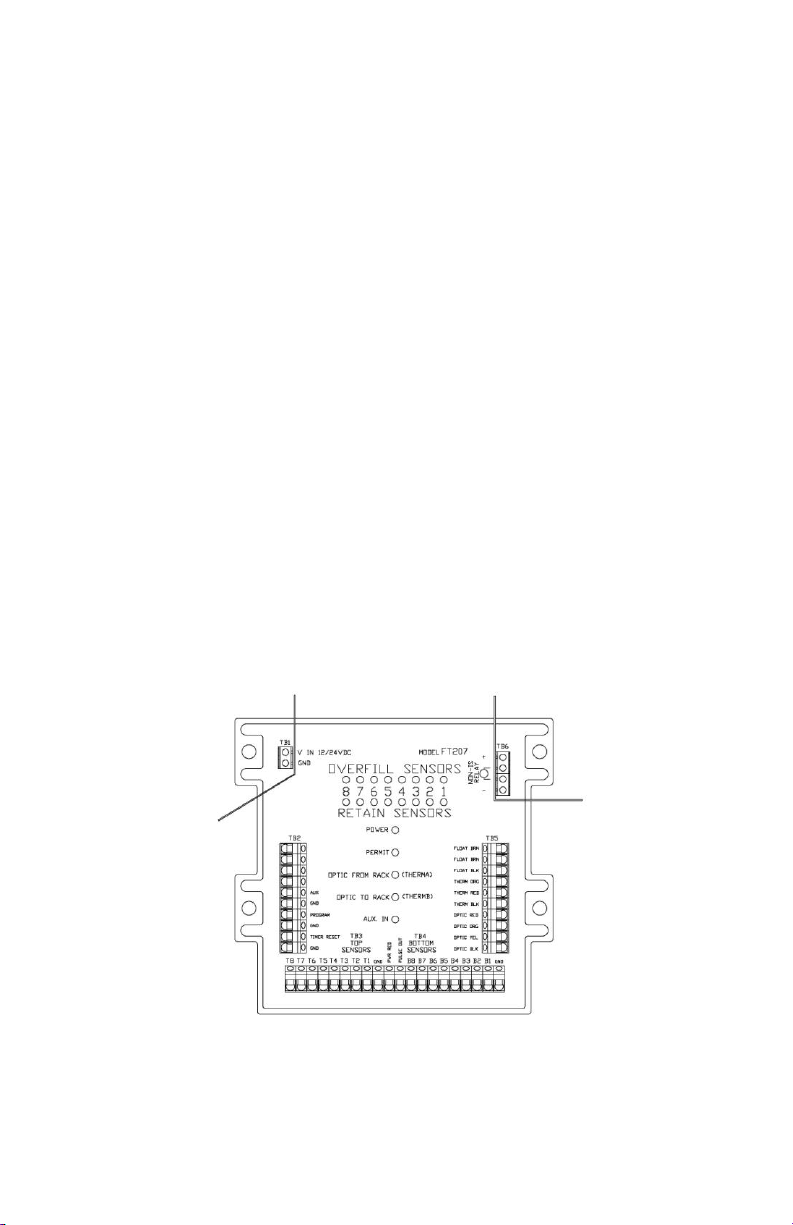
Fig. 1 FT208 Monitor

FloTech Programmable CheckMate Retain / Overfill Monitor
FT208 CheckMate REV G Page 5
Monitor Indicators
Refer to Fig. 1.
PWR LED
Yellow LED that indicates power is connected to the monitor.
PERMIT LED
Green LED indicates to the rack the sensors are permissive.
TOP LEDs
Overfill Sensor Indicators, ON indicates a wet sensor.
BOTTOM LEDs
Retain Sensor Indicators, ON indicates a wet sensor.
OPTIC FROM RACK (THERM A) LED
Red LED indicates no pulse from Optic Rack Monitor (YEL) or no
signal to Thermistor Rack Monitor (RED) A channel.
OPTIC TO RACK (THERM B) LED
Red indicated no signal to Optic Rack Monitor (ORG) or no signal
to Thermistor Rack Monitor (ORG) B channel.
AUX LED
Green LED indicates the Auxiliary input is permissive.
Monitor Connections
TB1 –12/24 VDC Power Connections
TB2 –Aux Input and Timer Reset. Program Key Input.
TB3 –Overfill Sensor Inputs
TB4 –Retain Sensor Inputs
TB5 –Optic and Thermistor Socket Connections
TB6 –Non I.S. Output Relay
FloTech Programmable CheckMate Retain / Overfill Monitor
Page 6 REV G FT208 CheckMate
Mounting Instructions
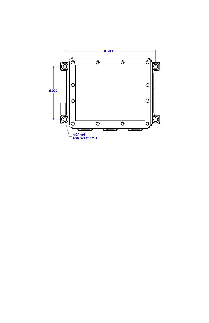
Fig. 2
Mounting Hole Detail
Monitor Housing
The FloTech model FT208 CheckMate Retain / Overfill Monitor
Housing is typically mounted in the trailer fitting storage box or
any flat surface within easy view of the bottom loading
connections. Leave the top cover on the monitor housing and hold
it in the position you wish to mount it. Using a black marker,
transfer the pattern of the four mounting holes to the mounting
surface. BEFORE drilling, check to make sure you will not drill
through or damage any existing trailer wiring or piping. Drill the
holes through and mount the monitor using four 5/16 inch nuts and
bolts.
Cable Installation Instructions
FloTech recommends you use FT404 jacketed 11-conductor cable
for up to 8 compartment systems. This cable is specially designed
to be oil, UV, and abrasion resistant. It incorporates a

FloTech Programmable CheckMate Retain / Overfill Monitor
FT208 CheckMate REV G Page 7
noble tin-plated stranded copper wire which resists corrosion.
When installed properly, this cable will provide years of reliable
service. See the Proper Wire Connections section for more
detailed directions about stripping and terminating the cables.
Monitor Housing
After the monitor housing is mounted, install FloTech FT402 cable
glands in the openings where needed. These are, as illustrated in
Fig.3: Power, Top Sensors, Bottom Sensors (if equipped) and
Socket. Route the lengths of FloTech FT404 cable through the
conduit openings. Cut the cables to length leaving approximately
8 inches of extra length inside the monitor housing.
Unused conduit openings in the sensor housings must have a ½
inch NPT pipe plug installed. Note that when using the FloTech
FT390 Dual Socket Assembly, you only need to install one cable
gland for the socket wiring.
Fig. 3
Monitor Housing Cable Routing Diagram

FloTech Programmable CheckMate Retain / Overfill Monitor
Page 8 REV G FT208 CheckMate
Wiring Instructions
Proper Wire Connections
Please read this section of the manual before attempting to wire the
FloTech FT208 Monitor. This section recommends some
„guidelines‟ for installing the system wiring that, when done
properly, will insure a long, trouble free service life for your
equipment.
CABLE STRIPPING
FloTech recommends using FT404 eleven conductor cable to wire
the Onboard Monitor System for up to 8 compartment systems.
When stripping the rubber jacket from the cable, FloTech
recommends using the FT9023 or equivalent Cable Stripper. This
stripper has an adjustable cutting blade depth setting. The depth
should be set to only cut through one-half to two-thirds of the outer
jacket thickness. This will insure that the insulation on the inner
conductors is not nicked. Any nicks or cuts in the wire insulation
can, over time, degrade the quality of the wire and lead to
intermittent or total failure.
CAUTION: Razor Knifes Will Cut The Inside Wire Insulation
BUTT SPLICE CONNECTIONS
FloTech recommends using the FT9022 or equivalent Crimp Tool
for securing the Butt Splice connections. Follow this process to
secure each connection:
1. Follow the Cable Stripping instructions in the previous
paragraph to expose the individual conductors of the wire.
2. Strip the insulation back on each conductor approximately
½ inch. Take care not to cut off any strands of wire. If too
many strands were accidentally cut off, cut the wires flush
with the insulation and strip again.
3. Hold the two wires to be connected together by the
insulation. Tightly twist the bare wires together. This
insures a good electrical connection.

FloTech Programmable CheckMate Retain / Overfill Monitor
FT208 CheckMate REV G Page 9
4. Fill a FloTech Butt Splice with Silicone RTV compound.
Insert the twisted wires into the filled splice. Check to see
that the bare wires are fully inserted into the splice and
RTV. Make certain that NO bare wire is protruding from
the splice.
5. Securely crimp the wires into the butt splice.
6. Give the splice and the wires a „tug‟ to make sure you have
a good mechanical connection.
TERMINAL BLOCK CONNECTIONS
Follow this process to secure each connection:
1. Strip approximately 3/8 inch of insulation back from the
end of the wires.
2. Tightly twist the strands of wire together.
3. Rotate the terminal block screws counter-clockwise a few
turns to relieve pressure on the wire retainer.
4. Insert the bare wire end into the terminal block.
5. While holding the wire in place, rotate the terminal screw
clockwise to tighten the wire retainer.
6. Once fully tightened, give the wire a slight „tug‟ to insure
that a proper connection has been made.
Monitor Wiring Connections
Before attaching wires to the FT208 CheckMate Monitor, please
read the following:
CAUTION: Turn off or disconnect power to the trailer before
wiring the monitor.
CAUTION: Only use the conduit opening marked “POWER
INPUT” as shown in Fig.3 to wire power to the monitor.
CAUTION: The FloTech FT208 CheckMate Monitor will not
work on POSITIVE GROUND electrical systems. Any attempt to
FloTech Programmable CheckMate Retain / Overfill Monitor
Page 10 REV G FT208 CheckMate
wire the monitor to a positive ground system will damage the
monitor and void the warranty.
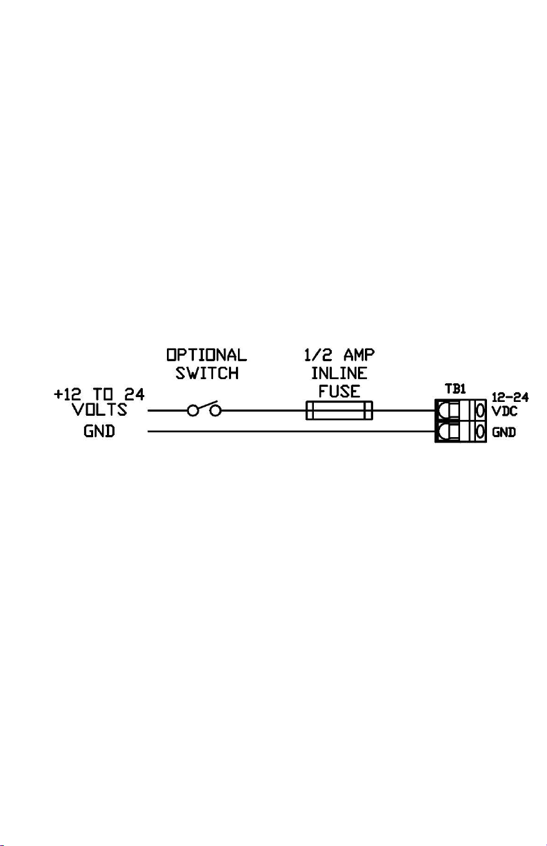
TB1 POWER Connections
Refer to Fig. 4. FloTech recommends routing the trailer power
through a weatherproof inline fuse holder (supplied) containing a
1/2 amp fast blow fuse to the monitor. Optionally, a switch can be
added in series with the fuse to the TB1 input. Connect the
positive power supply wire to the TB1 terminal marked “12/24
VDC”. This is the upper screw on TB1. Be careful that no stray
wires are touching the metal barrier or ground terminal. The
Ground wire connects to the TB1 terminal marked GND.
Fig. 4
Monitor Power Connections
TB3 & 4 TOP and BOTTOM SENSOR Connections
FloTech FT208 can be wired to work with 2 wire FT151 sensors or
API 5 wire FT101 sensors. FloTech recommends wiring the
sensors to the FT208 Monitor using FT404 11 conductor cable for
up to 8 compartment systems. FloTech FT404 cable is color coded
to ease installation and troubleshooting. A color coded wiring
schematic is provided in the back of this manual.
FloTech Programmable CheckMate Retain / Overfill Monitor
FT208 CheckMate REV G Page 11
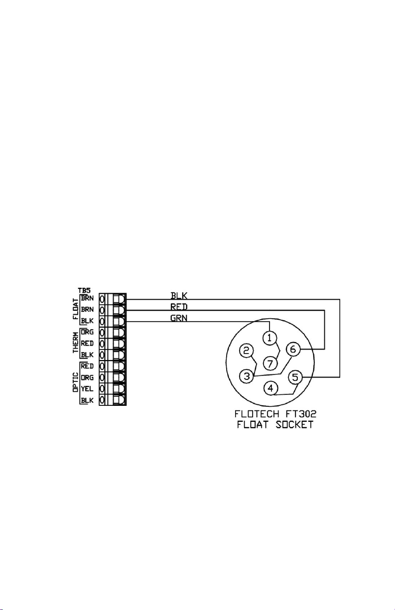
TB5 Socket Connections
These connections are wired to the appropriate socket(s) as
dictated by the Loading Terminals in your area. At this time,
FloTech offers the following sockets:
FT300 API Optic Socket
FT301 API Thermistor Socket
FT302 API Float Socket
FT303 Optic Contact Pattern with Thermistor J slot
FT304 Canadian / Euro Thermistor Socket
FT305 J560 Type Thermistor Socket
FT306 J560 Type Optic Socket
FT390 API Dual Thermistor and Optic Sockets
FT390V API Dual Therm and Optic Socket, Vertical
FT391 4 J-Slot Optic and Thermistor Sockets
Refer to Figs. 6 through 9 for socket wiring.
Fig 6.
Float Socket Connections

FloTech Programmable CheckMate Retain / Overfill Monitor
Page 12 REV G FT208 CheckMate
Fig. 7
Thermistor Socket Connections
Fig. 8
Optic Socket Connections
Another Socket Option is to install the FloTech FT390 Dual
Socket Assembly. This unit comes with the sockets pre-wired to a
length of FloTech eleven conductor cable. Refer to Fig. 9 for
wiring connections.

FloTech Programmable CheckMate Retain / Overfill Monitor
FT208 CheckMate REV G Page 13
Fig. 9
FloTech FT390 Socket Connections
TB2 AUX PERMIT Connections
Refer to Fig. 10. In order for the FT208 Monitor to work properly,
the AUX terminals must be connected together. This can be done
either by placing a shorting jumper across the AUX terminals
(factory installed) or by connecting the AUX terminals to a dry
relay contact. Examples of this would be a Hobbs switch or a
Vapor Recovery interlock switch. When the AUX connection is
made, the FT208 Monitor issues a PERMIT signal.
TB2 RESET Connections
Refer to Fig. 10. The Reset/Timer terminals connect to a Normally
Open push button switch. The primary function of this switch is to
override wet Retain Sensors for „Splash Blending‟ product. When
this button is pressed, the FT208 Monitor will issue a Permit signal
to the Rack without regard to the Retain Sensors for up to 90
minutes. The Permit signal will be disabled if any of the Overfill
Sensors become wet or there is signal activity on any Retain
Sensors that have been programmed as inactive.

FloTech Programmable CheckMate Retain / Overfill Monitor
Page 14 REV G FT208 CheckMate
Fig. 10
Timer/Reset and AUX Connections
TB2 PROGRAM Connections
Refer to Fig. 11. The FT208 Monitor must have a program module
installed in the PGM terminals ONLY during programming of the
monitor. This connection must be left open for normal operation.
See the Programming Section of this manual for detailed
instructions about programming this unit.
Programming
Overview
Before the FloTech FT208 Monitor can be put into service, it must
be programmed. This procedure informs the monitor which inputs
have sensors attached. These inputs are then labeled as ACTIVE
sensors. The remaining inputs that do NOT have sensors attached
are labeled as INACTIVE inputs. This insures that a PERMIT
signal will be issued only if ALL of the following conditions are
met:

FloTech Programmable CheckMate Retain / Overfill Monitor
FT208 CheckMate REV G Page 15
All active overfill sensors are dry.
All inactive overfill sensors are not connected.
All active retain sensors are dry or the Timer/Reset button
has been pressed.
All inactive retain sensors are disconnected.
The AUX input is jumpered or made through an external
contact.
If ANY of the above conditions are not met, the PERMIT signal
will not be generated.
Programming is accomplished in the following manner:
Procedure
To program the FT208 monitor:
1. Turn the power to the unit off.
2. Remove the reset switch wires from TB2.
3. Connect the programming module (10459) into TB2
bottom four contacts marked “Program, GND, Timer,
GND”. Switches should be face up.
4. Move SW1 to “PRGM” position.
5. Turn on the power. The sensor LEDs will sequentially
flash through the power up test pattern. This lights the
sensor LEDs individually from TOP #1 through TOP #8
and then through BOTT #1 through BOTT #8.
6. The sensor LEDs will light up the last valid configuration.
If the memory does not contain a valid configuration, the
sensor LEDs will default to lighting the top 1 sensor.
7. Press SW2 pushbutton to light the RED Top and Bottom
Sensors light to match the total number of top and bottom
sensors. Each time SW2 is pressed, the sensor LEDs will
shift to the next valid configuration. This sequence is Top
#1 to Top #8 and then Top and Bottom #1 to Top and
Bottom #8. This sequence will repeat every time the
pushbutton is pressed.

FloTech Programmable CheckMate Retain / Overfill Monitor
Page 16 REV G FT208 CheckMate
8. Once the LED pattern representing the number of
connected sensors is correct, move SW1 to “RUN”
position. The monitor will flash the sensor LEDs
sequentially through the test pattern. At this point, if all
connected sensors are dry and the AUX LED is on, the
PERMIT LED should light and no RED LEDs are lit.
9. Remove power from the trailer or turn power off to the
monitor. Remove the programming module, reconnect the
timer reset switch, and turn power back on to the monitor.
FIG. 11
PROGRAM MODULE POSITION
Operation
Normal Operation
When power is applied to the FT208 monitor, the unit will
sequentially flash the sensor LEDs through the power up test
pattern. This sequence is from the TOP #1 LED to the TOP #8
LED then from the BOTT #1 LED to the BOTT #8 LED.
Once this sequence is completed, the unit tests all the sensor
inputs.

FloTech Programmable CheckMate Retain / Overfill Monitor
FT208 CheckMate REV G Page 17
A PERMIT signal will be issued if:
All the sensor inputs that have been programmed as active
see dry sensor signals.
Any of the Retain sensors are wet and the Timer/Reset
pushbutton has been pressed.
All the sensor inputs that have been programmed as
inactive see no signals.
The AUX input is jumpered or made through an external
set of contacts.
A PERMIT signal will NOT be issued if:
Any of the sensors that have been programmed as active
are wet or are not connected.
Any of the sensors that have been programmed as inactive
see a sensor signal.
The AUX input is not jumpered or made through an
external set of contacts.
Retain Sensor Override
Should the operator want to load over product retained in the cargo
tank or the Retain Sensor is lit, press the Timer / Reset Switch.
This action will keep the PERMIT signal active for approximately
90 minutes and disregard and changes to the Bottom Retain
Sensors. After 90 minutes the monitor will switch non permissive
if retain sensors are still wetted.

FloTech Programmable CheckMate Retain / Overfill Monitor
Page 18 REV G FT208 CheckMate
Troubleshooting
Look up symptoms below and follow step by step instructions.
The PWR LED is not lit.
Measure the voltage on TB1. The input voltage must be
between 11and 24 VDC.
If the voltage is zero or low, work your way up the wiring to
the trailer nose plug. Check the inline fuse holder for bad
connections and for a blown fuse. Check the wiring and
trailer nose plug connections. Fuse housings my have
corrosion that causes the voltage to read low.
If the input voltage to TB1 is correct then replace the monitor.
NOTE: Do NOT use a battery charger to power the trailer. A
battery charger does not output a pure DC voltage and will
damage the onboard monitor.
System powers up and runs through power on
test sequence OK, then flashes all sensor LEDs
in an alternating pattern:
This means that the monitor is not programmed.
1. Go to the PROGRAMMING section of this manual and
program the monitor.
2. If the monitor fails to program, call FloTech for warranty
status and an RGA number.

FloTech Programmable CheckMate Retain / Overfill Monitor
FT208 CheckMate REV G Page 19
System will not load and one or more RED
sensor LEDs are lit in the inactive
compartments:
Follow these instructions for top or bottom sensors.
1. Remove onboard monitor cover.
2. Check the sensor inputs on TB3 and TB4 that are not being
used (inactive sensor inputs). Make sure there are no wires
connected.
3. Go to the PROGRAMMING section of this manual and
repeat this procedure, making certain to accurately program
the unit.
4. If the monitor still does not function properly, contact
FloTech Technical Service for further instructions.
System will not load and one or more RED
sensor LEDs are lit in the active compartments:
Follow these instructions for top or bottom sensors.
1. Remove onboard monitor cover.
2. Go to TB3. Remove sensor wire from the terminal block
that corresponds with the lit LED. Example: If LED TOP
#3 is lit, remove the sensor wire to terminal T3 (RED).
3. Select a compartment where the LED is NOT lit and
exchange that wire with the suspect wire. Example:
exchange failed sensor wire TOP #3 (RED) with the
working TOP #2 wire (GRN).
4. If the lit sensor LED does not move to the new position, the
monitor is defective. Example: LED TOP #3 top stays lit
after the sensor wires are switched. Replace the onboard
monitor chassis with a FloTech model FT207 replacement
chassis.
5. If the lit sensor LED moves to the new switched
compartment, the problem is with the sensor or wiring.
Example LED TOP #3 go out and LED TOP #2 lights,
return the wires to the original positions.

FloTech Programmable CheckMate Retain / Overfill Monitor
Page 20 REV G FT208 CheckMate
6. Open all the sensor caps and check each wiring connection.
Look for pinched wires that may short the sensor signal to
ground. Also, look for defective crimp connections.
7. Measure voltage across the failed sensor wires (Black to
Red). Voltage should measure 8-10 VDC.
8. If steps 6 and 7 check OK, replace the sensor with a
FloTech FT150.
NOTE: A quick test of the sensor can be accomplished by
connecting the sensor directly to the onboard monitor. Example:
Remove sensors wires from monitor ground (WHT) and the TOP
sensor 1 (BRN) and connect the sensor to be tested. If the sensor
is good the RED TOP #1 LED with NOT light. If the sensor is
defective the Diagnostic LED WILL light.
System will not load, has no green AUX LED and
no green PERMIT LED, power LED is lit and no
red sensor LEDs are lit.
1. Check the TB2 AUX input. This input must have a closed
switch or jumper connected to allow the monitor to load.
The AUX input has its own green LED. This LED must be
lit to send a permissive signal to the load rack.
2. Check to see if a jumper is connected to TB2 AUX. If TB2
AUX has no connections, add a jumper.
3. If TB2 AUX has a wire connection, follow the cable to the
switch. This switch is typically connected to a vapor
recovery interlock or to a brake air lines interlock. Activate
the switch and see if the AUX green LED is lit. If not
repair the air switch. If the air switch appears OK then
check the monitor by installing a jumper wire to force the
AUX LED on. If the Aux LED can‟t be forced on then
replace the monitor.
Other manuals for FloTech FT208
1
Table of contents
Languages:
Other Dixon Bayco Monitor manuals


