DIY BBQ Angela 'L' Island User manual

Angela ‘L’ Island Module assembly
Instruction
Manual
Easy-to-Follow

If you are still having trouble putting your module together, we are here to help. Contact us at 800-289-3492 or email [email protected].
Copyright Notice
Warnings
Notice of Limited Liability
Arbitration Agreement
This instruction manual is protected under Copyright Law of the United States of America.
This copy of the instruction manual is for the sole use of the original purchaser. A license to use the information contained herein is granted to
the original purchaser by the author.
No part of this instruction manual, including but not limited to, photographs, pictures, diagrams, or illustrations may be reproduced, copied or
transferred in print or electronically to third parties without the express written permission of the author. Any copying, retransmission, editing or
distribution without the express written permission of the author will terminate the license and all copies in the possession or distribution by the
purchaser will be considered unlicensed and therefore in infringement of U.S. Copyright Law.
Furthermore, if the purchaser wishes to use the information contained herein for the creation or supplement of business, whereby BBQ islands
would be part of the business, then the purchaser is not permitted to use or distribute any of the enclosed information within that business without
the express written permission of the author.
When working with metal, the edges are very sharp and may have small splinters across the edges. Be extremely careful when handling each piece.
It is highly recommended to wear safety glasses and gloves at all times while building your modules. Eye protection is required when cutting or
screwing metal pieces to protect against errant metal pieces and particles.
Keep children and animals away from the metal pieces and completed frame kits.
Please follow all manufacturer directions on how to properly install BBQ products.
Check with your local codes on construction for the required permits you may need for construction of your BBQ island.
Utility lines should only be installed by a licensed plumber or electrician per the code in your area. Do not forget to get a permit if required by
local laws or regulations.
Please read all directions on how to install your DIYBBQ island modules. Installation of the product is at your own risk; DIYBBQ, LLC is not
liable for misuse of the module frame kits nor for damage to any of your BBQ products.
NOTICE: DIYBBQ , LLC shall NOT be liable for incidental and consequential damages, directly or indirectly sustained to any person(s),
equipment, tools, or appliances during or after the installation of any BBQ island, related directly or indirectly to the installation and operation
of any BBQ island or appliances, nor for any loss caused by application of these goods not in accordance with current printed instructions or
for other than the intended use. DIYBBQ , LLC’s liability is expressly limited to replacement of defensive goods. Any claim shall be deemed
waived unless made in writing to DIYBBQ, LLC at 26520 ADAMS AVE., MURRIETA, CA 92562 within thirty (30) days from the date it
was or reasonably should have been discovered.
USE OF OR PURCHASE OF ANY DIYBBQ , LLC PRODUCTS, OR ANY GOODS AVAILABLE FOR PURCHASE THROUGH
DIYBBQ.COM REQUIRES THAT ALL CLAIMS BE SETTLED UNDER THIS BINDING ARBITRATION PROVISION, WHICH
AFFECTS YOUR LEGAL RIGHTS AND MAY BE ENFORCED BY EITHER PARTY.
In the event a dispute shall arise between DIYBBQ , LLC and any purchaser of any DIYBBQ, LLC product or good available through
diybbq.com, it is hereby agreed that the dispute shall be referred to a USA&M oce to be designated by USA&M National Headquarters for
Arbitration in accordance with the applicable United States Arbitration and Mediation Rules of Arbitration. The arbitrator’s decision shall
be nal and legally binding, and judgment may be entered therein.
Each party shall be responsible for its share of the arbitration fees in accordance with the applicable Rules of Arbitration. In the event a party
fails to proceed with arbitration, unsuccessfully challenges the arbitrator’s award or fails to comply with the arbitrator’s award, the other party
opposing party is entitled to costs of suit, including a reasonable attorney’s fee for having to compel arbitration or defend or enforce the award.

3
Contents
68-Inch Quick Panel Module Assembly (x2)
5
90 Corner Quick Panel Module Assembly
10
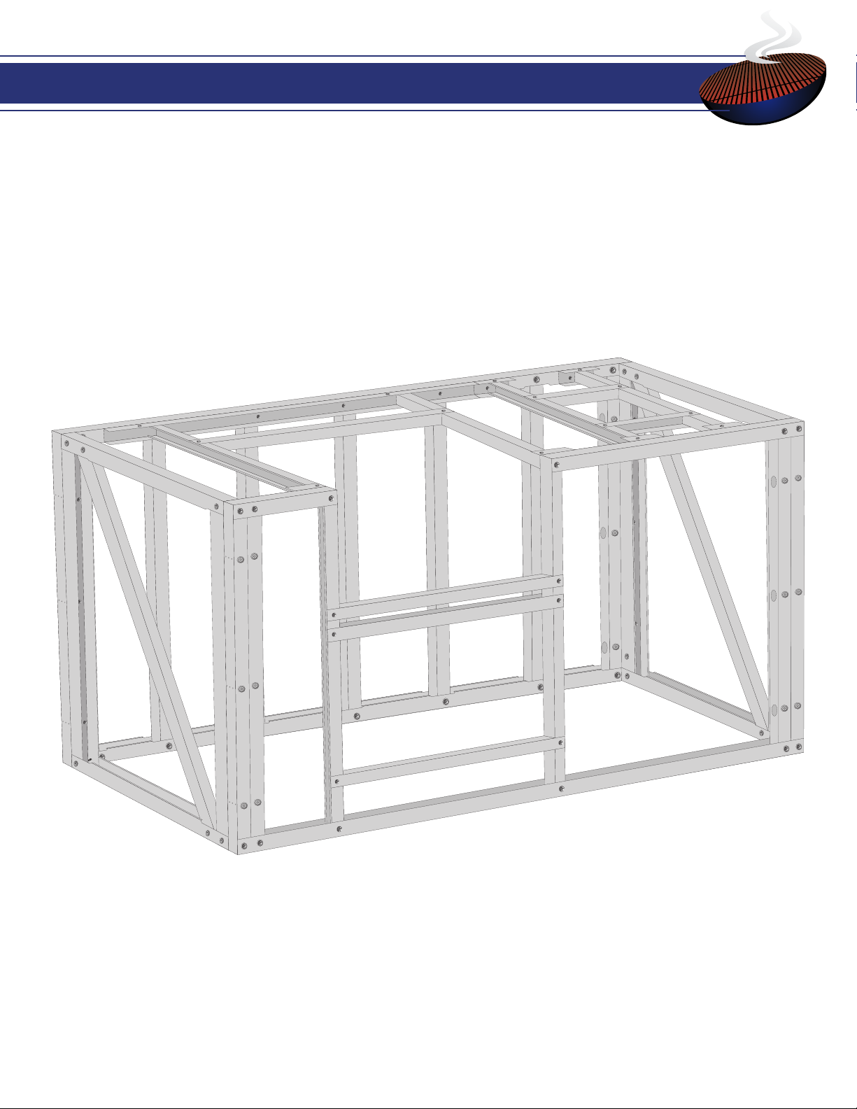
Angela ‘L’ Island Full Assembly
43
Cutout Kit Assembly For Grill, Doors & Side Burner
14
Cutout Kit Assembly For Refrigerator & Sink
33
Required Tools
4
Slide-In & Drop: 17 Double Doors: 26 Drop-In Only: 29
Slide-In Only: 35 Drop-In Only: 39

Proper Safety equipment is extremely important.
Always wear safety glasses and gloves when assembling your modules.
Using proper tools will make the project much easier to do and will help you obtain a properly built project. This list is of the basic tools
you’ll need to build your modules. You may use whatever tools you deem necessary to complete your project in the easiest way possible. All
tools listed here and others you may wish to acquire can be found at Lowes®, Home Depot®, Amazon and other on-line retailers.
A cordless impact driver will make steel frame assembly easier and help protect the edges of the HardieBacker®cement board from cracking
during installation onto the frame.
Professional Tips
Required Tools for Assembly
Additional Tools
Vise Clamps
Rafter Square
Cutoff Wheel
HammerPick
Cordless Drill
Spring Clamps
Tape Measure
Aviation Snips Magnetic Level
Carpenter Square Marker
Useful Terms
Perimeter Walls: The front and back walls of a module.
Cross Channels: The side walls of a module that connect to the Perimeter walls.
Track: The top and bottom pieces of a Perimeter or Cross Channel wall.
Stud: The sides and inside pieces of a Perimeter or Cross Channel wall.
Angle Brace: A piece that supports the tracks to the outer studs of the front and back walls of an unassembled module.
Quick Panels: The back and front walls of an Assembled Module that include a second support stud on each end for extra durability.
Union Plate: A at rectangle with pre-drilled holes to help assemble or add extra durability to
module walls, cutouts and extra wall accessories. (Sold Separately)
L-Bracket Plate: A larger union plate in the shape of an L. (Sold Separately)
Dimple: The indentation around a precut hole within a track or a stud.
Web Holes: The small, precut holes, usually appearing in sets of three on the back side of a Cross
Channel wall that act as a guide for drilling when attaching Cross Channel walls to the front and
back walls of a module.
Assuage: The small creases that appear on the ends of a stud that allows for easier assembly (see
image to right).
Catch Track: An additional stud that runs perpendicular to Perimeter and Cross Channel walls
within the center of a module. (Used in specialty and cutout modules.) Assuage

68-inch Quick Panel Assembly (x2)

Cross Channel (CC) (x4)
Screws
2 Complete Front Walls
2 Complete Back Walls
4 Complete Cross Channel (CC) Walls
5 Front Wall Studs (These will be packaged/taped inside the Front Wall tracks as seen above).
24 Self-Tapping Screws
?
What’s in the box
Check List
Front Wall (x2)
Back Wall (x2)

7
Module Assembly
Step
1
1Remove the studs from the front wall and set them aside in a safe place.
Slide the le Cross Channel (CC) wall so that it aligns perpendicular to the edge of the le side of the back wall.
2
2
Step

8
Repeat steps 2 and 3 to attach the second CC wall to the right back Perimeter wall.
4
Step
4
Attach the CC wall to the back Perimeter wall by drilling at least three (3) screws through the pre-drilled web holes
found on the inner side of the CC wall.
Note: e web holes located on the outer studs of the CC walls align with the pre-drilled holes in the perimeter wall.
Use the center web hole in each row to drill the perimeter wall to the CC wall.
3
Step
3
Drill
Inside
CC
Wall
Stud
Drill
Inside
CC
Wall
Stud

9
Place the front Perimeter wall in place and drill screws through the web holes (as seen in step 3) to attach the front
wall to both CC walls.
5
5
Step
With Front Wall
Studs Placed
Drill
Inside
CC
Wall
Stud
Drill
Inside
CC
Wall
Stud
You should now have a complete module. You may lay the front wall studs to the side for now or place them into the
front wall (see inset) for safe keeping until you know the dimensions and placement of your cutouts.
6
6
Step
Repeat all steps from Page 7 to Page 9 to assemble the second 68-Inch Module. You should now have two (2)
complete 68-Inch Modules.
7
7
Step

90-Corner Quick Panel Assembly

11
?
What’s in the box
2 Cross Channel Walls
2 Perimeter Walls
Self-Tapping Screws (Minimum amount needed for assembly: up to 20)
Check List
Perimeter Walls
Cross Channel
Walls
Screws

12
Module Assembly
Step
1
1Slide one Cross Channel (CC) wall so that it aligns perpendicular to the inside edge of the le Perimeter wall to
form the le and back sides of the module.
Attach the back Cross Channel wall to the le Perimeter wall by drilling at least three (3) screws inside the stud of
the CC wall.
Note: e web holes located on the outer studs of the CC walls align with the pre-drilled holes in the perimeter wall.
Use the center web in each rowhole to drill the perimeter wall to the CC wall.
2
2
Step
Drill
Inside
CC
Wall
Stud
Drill
Screws
Inside
CC
Wall
Stud

13
Repeat steps 2 and 3 to attach the
back Cross Channel wall to the
right Perimeter wall. Make sure the
right wall is on the outside of the
back wall.
3
Step
3Place the front Cross Channel wall
in between the right and left Perim-
eter walls and drill screws (as seen
in step 3) to attach the front wall to
each side wall.
4
Step
4
You should now have a complete 90 Corner Quick Panel Module.
5
5
Step
Drill
Inside
CC
Wall
Stud
Drill
Inside
CC
Wall
Stud
Cutouts for Grill, Doors & Side Burner

15
?
What’s in the box
1 Long Catch Track
2 Short Catch Tracks
2 Countertop Studs
2 Precut Appliance Tracks
Self-Tapping Screws (Amount needed for Assembly: up to 26)
Check List
Countertop Studs
Long Catch Track
Short Catch Tracks
Precut Appliance Tracks
Screws
2 Precut Appliance Tracks
8 Self-Tapping Screws
Check List
Screws
Precut Appliance Tracks
Slide-In and Drop Cutout (Pages 17 - 25)
Double Door Cutout (Pages 26 - 28)

16
?
What’s in the box
Drop-In Only Cutout (Pages 29 - 32)
4 Short Catch Tracks
2 Countertop Studs
2 Precut Appliance Tracks
20 Self-Tapping Screws
Check List
Countertop Studs
Short Catch Tracks
Screws
Precut Appliance Tracks
PLEASE READ - IMPORTANT
The following cutout instructions (pages 17 - 32) for the Grill, Side Burner and Double Doors are just
one conguration. You may place the cutouts anywhere within the modules. If you choose to alter
the layout of the preferred cutout conguration, the instructions can still be used as a general guide.

17
Slide-In & Drop Cutout (Grill)
Step
1
1Clamp the Long Catch Track to the back Perimeter Wall of your module with Vice Clamps about where you would like
to place your appliance. (Make sure to leave enough room for the Side Burner cutout (page 29)). Make sure that the top
of the Long Catch Track is ush with the top of the Perimeter Track.
Note: If your Catch Tracks are too long for your specic module, please see page 47 for instructions on how to
properly cut your Catch Track(s) to t your module.
Add the amount of screws that match the number of studs in the back Perimeter Wall of your module.
2
2
Step
Professional Tip -
Placement of Screws
To avoid drilling a screw into the screws already placed
in your Perimeter Wall, make sure to drill the screws next
to each stud instead of in the direct center of the stud.

18
Slide one of the Countertop Studs
into one of the Short Catch Tracks.
Make sure the corners are ush on
the far right side.
3
Step
3Drill screws into both sides of the
Short Catch Track to secure it to
the Countertop Stud.
4
Step
4
1
2
Make Flush
Slide the second Countertop Stud
into the second Short Catch Track.
Make sure the corners are ush on
the far left side.
5Drill screws into both sides of the
Short Catch Track to secure it to
the Countertop Stud.
6
5 6
StepStep
2
Make Flush

19
Slide the open end of the L-Shaped Countertop Studs built in steps 3 through 6 into the Long Catch Track and
then clamp the Short Catch Tracks to the top track of the front Perimeter Wall of your module. Make sure the tops
of the Short Catch Tracks are ush with the top of the Perimeter Wall Track.
Note: Make sure the smooth sides of the Countertop Studs are facing the appliance.
7
7
Step
Smooth side
toward the
appliance
Open side
away from
the appliance
Place the rst Appliance Track in-between the Countertop Studs near the back of the module. The Appliance
Track has been precut to t the width of the appliance. To best position the appliance, place one side of the Appli-
ance Track ush against the rst Countertop Stud, then readjust the second Countertop Stud to rest ush against
the other end of the Appliance Track.
8
8
Step
Make sure edges of the Appliance
Track are ush with the edges of
the Countertop Studs.

20
Measure the distance of the Appliance Track from the front Perimeter Wall Track of your module to make sure it
matches the length of the appliance that will be placed within this area. If the size is incorrect, slide the Appliance
Track forward or back along the Countertop Studs until the size between the Appliance Track and the Perimeter
Wall Track matches the length of the appliance.
Note: Add an eighth or a quarter of an inch to the size of your appliance to make sure the appliance slides in
easily.
9
9
Step
Drill screws into the top and bottom of the Countertop Studs and the Appliance Track (for a total of eight (8)
screws).
10
10
Step
Length between the smooth side of
the Appliance Track and the front
Perimeter Wall Track will equal the
length of the appliance.
1
2
3
5
4
68
7
Popular Grill manuals by other brands

Weber
Weber Genesis 2300 Series owner's manual

Koolatron
Koolatron TotalChef TCRF08BN instruction manual

Steba
Steba VG 110 Instructions for use

Louisiana Grills
Louisiana Grills CS 680 owner's manual

Inoksan
Inoksan PERFECT 700 Series instruction manual

Heatlie Barbecues
Heatlie Barbecues Island Gourmet Elite Installation instructions manual


