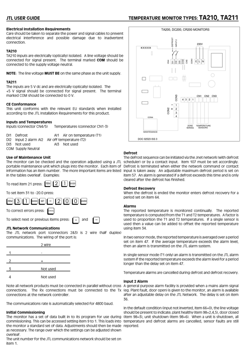
DK-Audio MSD100 User manual


MSD100
MSD100AES/MSD100AES-SA
MSD100T/MSD100T-SA
MSD150C
MASTER STEREO DISPLAY
USER’S MANUAL

Copyright © 1995, 1997, 2002, DK-Audio, Herlev
All rights reserved. No part of this publication may be
reproduced or distrinbuted in any form, or by any means,
without prior written consent from DK-Audio, Herlev,
Denmark.
Trademarks
Analog Devices is a registered trademark of Analog
Devices, Inc. USA
Crystal is a registered trademark of Crystal
Semiconductor Corp., USA
Note: This manual covers all MSD100 Series models.
The main text refers to the MSD100 but applies to all
models. Special notes, subsections and tables are
provided to describe operational features that are unique
to specific models.

MSD100 USER’S MANUAL i
CONTENTS
1. Introduction
1.1 Using This Manual.......................................... 1-3
1.2 Notation Conventions ...................................... 1-4
1.3 Related Documentation.................................... 1-5
1.4 If You Need Help............................................ 1-5
1.4.1 RMA Request......................................... 1-5
2. Overview
2.1 Audio Metering............................................... 2-1
2.2 MSD100 Applications....................................... 2-2
2.3 Physical Overview........................................... 2-3
2.4 Audio Inputs .................................................. 2-3
2.5 Power Supply................................................. 2-4
2.6 Codec Circuit................................................. 2-5
2.7 Decoder........................................................ 2-6
2.8 DSP Microcomputer ........................................ 2-6
2.9 EPROM (Program Storage Media)...................... 2-6
2.10 LCD Display................................................. 2-7
2.11 Model Comparison Summary ........................... 2-7
3. Installation
3.1 Mounting....................................................... 3-1
3.1.1. Mounting for Horizontal and Vertical
Adjustment ................................................... 3-1
3.1.2 Mounting for Horizontal Adjustment Only ..... 3-2
3.2 Audio Connections .......................................... 3-2
3.3 Power Connections ......................................... 3-4

CONTENTS
ii MSD100 USER’S MANUAL
4. Operation
4.1 Main Display and Control Keys.......................... 4-1
4.1.1. Initial Display at Power Up........................ 4-2
4.1.2 Function Keys......................................... 4-3
4.1.3 Additional Information Displayed on
Digital Models ......................................... 4-3
4.2 Phase Correlation Meter................................... 4-4
4.3 Audio Vector Oscilloscope................................ 4-3
4.4 Peak Programme Meter (PPM) .......................... 4-5
4.4.1 International PPM Scales Supported............ 4-6
4.5 Level Meters.................................................. 4-7
4.6 Adjusting Input Gain (20 dB)............................. 4-7
4.7 Using the Utilities Menu ................................... 4-8
4.7.1 Adjusting Brightness ................................ 4-8
4.7.2 Adjusting Viewing Angle (Contrast).............. 4-9
4.7.3 Selecting Inverted Display ........................4-10
4.8 Selecting PPM Options ...................................4-10
4.8.1 Selecting Preferred PPM Scale..................4-10
4.8.2 Selecting the PPM Reference Level............4-11
4.8.3 Using the LED Overload Indicators.............4-11
4.8.4 Using the PPM Peak Hold Function............4-12
4.8.5 Using the PPM FAST Mode ......................4-13
4.9 Changing Default Settings ...............................4-14
4.10 Bitstream Status Display................................4-15
4.10.1 AES/EBU Decoding Mode.......................4-15
4.10.2 Consumer Decoding Mode......................4-16
4.10.3 Displaying Channel Information................4-16
4.11 Spectrum Analysers......................................4-17
4.11.1 FFT Spectrum Analyser..........................4-17
4.11.2 1/3-Octave Spectrum Analyser.................4-17

CONTENTS
MSD100 USER’S MANUAL iii
Appendix A. Specifications
A.1 Power Supply................................................A-1
A.2 Cabinet Dimensions .......................................A-2
A.3 Level Meter...................................................A-2
A.4 Phase Correlation Meter ..................................A-2
A.5 Audio Vector Oscilloscope................................A-3
A.6 LCD Display..................................................A-3
Glossary
Terms, Abbreviations, Acronyms...................Glossary-1
Product Registration Form
Registration Card...................................Registration-1
Index
Index ...........................................................Index-1
List of Tables
Table 2-1 MSD Rear Panel Connections ................... 2-3
Table 2-2 MSD Compasrison Summary..................... 2-7
Table 3-1 MSD Series Audio Connections ................. 3-3
Table 3-2 MSD Supply Voltage Specifications............ 3-5
Table 4-1 Ideal Stereo and Mono Signals.................. 4-4
Table 4-2 Available Scales..................................... 4-6
Table 4-3 Data Information for AES/EBU Mode..........4-15

CONTENTS
iv MSD100 USER’S MANUAL
List of Figures
Figure 1-1 MSD Master Stereo Display ..................... 1-1
Figure 2-1 MSD100 Dimensions .............................. 2-3
Figure 2-2 RCA and XLR Connectors ....................... 2-4
Figure 2-3 Rear-Panel Power Connection.................. 2-4
Figure 3-1 MSD100 Mounted in Bracket.................... 3-2
Figure 3-2 Female XLR Connections MSD100T.......... 3-4
Figure 3-3 DC Power Socket .................................. 3-4
Figure 4-1 MSD Main Display .................................4-1
Figure 4-2 MSD100AES/SA w/Sampling Frequency..... 4-3
Figure 4-3 MSD100 Displays for Signal Conditions...... 4-5
Figure 4-4 Available PPM Scales ............................ 4-7
Figure 4-5 Set Brightness/ INV Menu ....................... 4-8
Figure 4-6 Set Viewing Angle Menu......................... 4-9
Figure 4-7 FFT Spectrum Analyser .........................4-18

1. INTRODUCTION
This section provides a description of the MSD100 Series,
lists related documentation and notation conventions, and
provides product support contact information.
The DK-Audio MSD100 Master Stereo Display Series
models are universally recognized professional audio
metering system for broadcast and studio applications.
The MSD100 Series supplements the human ear by
providing a visual representation of audio level, phase,
stereo imaging and more. The entry-level MSD100 is
shown in Figure 1-1.
FIGURE 1-1. MSD100 MASTER STEREO DISPLAY

INTRODUCTION
1-2MSD100 USER’S MANUAL
The MSD Series models covered in this manual are:
•MSD100 •MSD150C
•MSD100AES •MSD100AES-SA
•MSD100T •MSD100T-SA
Note: This manual covers all MSD100 Series
models listed above. The main text refers to
the MSD100 but applies to all models. Special
notes are provided to describe operational
features that are unique to specific models.
The MSD100 Series models deliver monitoring
capabilities beyond traditional instruments such as bar
graphs, LEDs and oscilloscopes.
All MSD100 Series units provide the following basic
functions:
•Phase Meter
•Audio Vector Oscilloscope
•Level Meter with selectable PPM/VU scales
•Selectable reference level
•LED overload Indicator
•Peak Hold
The MSD100T/SA adds the following features:
•Spectrum Analyser
•Transformer balanced audio inputs with XLRs
The MSD100AES/SA adds the following features:
•Spectrum Analyser
•Digital Data Readout

INTRODUCTION
MSD100 USER’S MANUAL 1-3
1.1 USING THIS MANUAL
This manual contains information and instructions
necessary to install, configure and operate the MSD100,
MSD100AES, MSD100AES-SA, MSD100T, MSD100T-SA
and MSD150C. It provides step-by-step instructions you
must perform to install and operate your MSD100 Series
model successfully. This manual contains the following
information:
Section 1 Introduction. Includes a brief description of the
MSD100 Series, lists related documentation,
provides product support contact information.
Section 2 Overview. Describes the MSD100 functions,
hardware components, physical enclosure, and
connectors.
Section 3 Installation. Provides instructions on how to
install the unit and connect audio and power
cables.
Section 4 Setup and Operation. Provides instructions on
how to operate the MSD and use the main
display, control keys, phase correlation meter,
audio vector oscilloscope, and peak programme
meter. It describes how to interpret displayed
data, adjust PPM peak hold meters, input gain,
utilities, brightness, and viewing angle.
Section 5 Digital AES/EBU Versions. Describes the
operation of the bitstream status display on the
digital audio MSD100AES and MSD100AES-SA
models.
Section 6 Spectrum Analyser Versions. Describes the
operation of the FFT-Spectrum Analyser of the
MSD100T-SA and MSD100AES-SA models.

INTRODUCTION
1-4MSD100 USER’S MANUAL
Appendix A Specifications. Provides the technical and
physical specifications for the MSD unit.
Glossary Glossary. Provides full spelling of acronyms
and abbreviations and the definitions of special
industry terms used in this manual.
Index Index. Provides an alphabetical index to key
terms used in this manual.
Product
Registration Registration Card. This page can be used if
the registration card is missing. Either the form
or the card can be mailed or faxed to DK-Audio
1.2 NOTATION CONVENTIONS
Before you begin working with the MSD100, familiarize
yourself with the notation conventions used in this manual.
Convention/Symbol Meaning/Example
Used together with italic type to point
out important information and notes.
Important cautions and safety-related
information, such as “Never apply power
while the housing is removed”.
Boldface Type Keys you must press, such as [LEFT],
[UTIL], [CAL], [DEFAULT]and [EXIT]
keys.
Italic type Emphasizes operational differences of
specific models, such as This function is
not available on the MSD100AES.

INTRODUCTION
MSD100 USER’S MANUAL 1-5
1.3 RELATED DOCUMENTATION
The following manuals provide additional information
about related technologies and products, but are not
required to install or operate the MSD100 Series.
•MSD200/800 Series User’s Manual
•MSD600 Series User’s Manual
•MSD Compact (MSD500A/B) Series User’s Manual
•Audio Metering, Eddy Bøgh Brixen,
Broadcast Publishing & DK Audio A/S, Denmark 2001
1.4 IF YOU NEED HELP
If you need assistance while working with your MSD100
Series product, please contact us at DK-Audio:
Telephone +45 44 85 02 59 (direct)
+45 44 85 02 55
Fax +45 44 85 02 50
Mail registration DK-Audio –Marielundvej 37D
DK-2730 Herlev –Denmark
Email info@dk-audio.com
service@dk-audio.com
Web address www.dk-audio.com
You can access the following Technical Support
information from our web site:
•Product Specifications
•Software downloads
•User’s Manuals
•FAQ (Frequently Asked Questions)
•Direct contacts

INTRODUCTION
1-6MSD100 USER’S MANUAL
1.4.1 RMA REQUEST
To return a DK-Audio or PTV product to us for repair or
calibration/modification, you must submit a Return
Merchandise Request (RMA) form.
You can request to receive the RMA form as follows:
By Telephone +45 44 85 02 55
By email service@dk-audio.com
Or, you can download the RMA form (as a PDF file)
directly from our website:
Download From www.dk-audio.com
1. Click Technical Support
2. Click the link to the RMA form.
After you complete the RMA form, please email or fax the
form to us at DK-Audio.

2. OVERVIEW
This section provides an overview of MSD100 audio
metering functions, applications, a physical description
and a summary comparison table. It also covers audio
inputs, power supply, codec circuit, decoder, DSP
microcomputer, Eprom and LCD display.
2.1 AUDIO METERING
The DK-Audio MSD100 Master Stereo Display Series
provides producers, sound engineers and technicians with
an objective visual representation of audio characteristics.
By supplementing the human ear with meters and scopes
based on international standard measurement scales, the
risk of over-reliance on subjective criteria is minimized.
All models in the Master Stereo Display Series ranging
from the simple monochrome version to the multi-channel
colour version provide the following basic functions:
FUNCTION DISPLAY
Phase meter Average phase relationship between two
audio signals
Level meter Level of signal with peak and overload
protection with seven selectable
international scales and reference levels
Audio vector
oscilloscope Picture of audio signal indicating mono or
stereo patterns

OVERVIEW
2-2DK-AUDIO MSD100 USER’S MANUAL
2.2 MSD100 APPLICATIONS
The small physical size and versatility of the Master
Stereo Display makes it ideally suited for:
•Master metering of any mixing console
•Studio and broadcast facilities
•OB-Vans
•Hard disc recording and editing systems
•Home studios (MSD-100)
The MSD100 Series provides serious audio professionals
with these essential features backed by a 2-year warranty:
•Phasemeter
•Audio vector oscilloscope
•Level meter with 6 selectable PPM/VU scales
•Individually selectable input reference levels with an
additional 20db of input gain (100, 100T/SA)
•LED overload indicator
•Peak hold
•Simultaneous display of stereo information and
programme levels
•Softkey selectable PPM characteristics
•Support for most international standards
•Digital processing, eliminating scale errors
•Storage of all user defined parameters in NV-RAM
•Long life CCT backlight (15.000 hours)
•Digital Data Readout (100AES/SA)
•FFT and 1/3 octave spectrum analyser (100T/SA and
100AES/SA)

OVERVIEW
DK-AUDIO MSD100 USER’S MANUAL 2-3
2.3 PHYSICAL OVERVIEW
Each MSD100 Master Stereo Display Series model is
housed in a cabinet measuring 179 mm wide x 129 mm
high (without bracket) x 39 mm deep. The display area is
69 x 69 mm.
179 mm 129mm
FIGURE 2-1. MSD100 DIMENSIONS
2.4 AUDIO INPUTS
The rear-panel audio connection and signal types vary by
model as described in Table 2-1.
Table 2-1. MSD100 Series Rear Panel Connections
Model Connector Type Signal type
MSD100
MSD150C RCA phono plugs Unbalancedstereo
MSD100AES
MSD100AES-SA Female XLR sockets (2) Balanced AES/EBU
(digital)
MSD100T
MSD100T-SA Female XLR socket (1) Balanced

OVERVIEW
2-4DK-AUDIO MSD100 USER’S MANUAL
FIGURE 2-2. RCA (LEFT) AND XLR (RIGHT) CONNECTORS
2.5 POWER SUPPLY
The 2,1 mm power input connector on the rear of the
MSD100 cabinet accepts 9-30V DC.
FIGURE 2-3. REAR PANEL POWER CONNECTION
The power supply is based on both switch-mode and
linear regulation principles and accepts both AC and DC
inputs.
Recommended supply voltages are:
•9 to 30V DC
•9 to 20V AC, 50Hz
An optional 230V power supply, such as the Model
MA15-150, is available with the following typical voltages:
Input: 100-240V AC, 47-63 Hz, 1 .0A
Output: 15V DC, 1.0A, 15W max.
Caution: High voltage for the LCD background
light is generated internally. Use special care
when servicing as 600V AC is present on the
circuit board.

OVERVIEW
DK-AUDIO MSD100 USER’S MANUAL 2-5
2.6 CODEC CIRCUIT
The Codec circuit, included only on models MSD100,
MSD100T, MSD100T-SA, and MSD150C, integrates key
audio data conversion and control into a single IC. The
Codec circuits include the following features:
Anti-alias filter Low-pass filter used at the input of the ADC
for determining the upper cut-off frequency
(fmax) of the analog signal before conversion
to digital.
Anti-imaging
filter Steep low-pass filter used after the DAC to
reduce the stair-step waveform (w/ high
frequency artifacts or images) and
reconstruct a smooth replica of the original
signal.
ADC Analogue-to-digital converter. Circuit that
converts an analogue signal to a digital
signal.
DAC Digital-to-analogue converter. Circuit that
converts a digital signal to an analogue
signal.
Gain control Independent for each channel
Digital
attenuator Attenuates signals before the DAC input
Digital
interpolation
filter
Provides oversampling and stereo
separation before the DAC input
Switched
capacitor and
continuous-
time filters
On-chip circuit for removing Nyquist images
from the DAC’s analogue stereo pairs

OVERVIEW
2-6DK-AUDIO MSD100 USER’S MANUAL
Dynamic
range and
signal-to-
noise
>80dB over 20kHz audio range
Sampling rate 48kHz, fixed
2.7 DECODER
The Crystal®CS8412 decoder, installed on digital models
MSD100AES and MSD100AES-SA, performs the
following:
•Detects sampling frequency-32kHz, 44,1 kHz, 48kHz
•Determines whether the signal is AES/EBU or SP/DIF;
Signal sources of both types can be used
2.8 DSP MICROCOMPUTER
The Analog Devices®ADSP-2181 single-chip
microcomputer is optimized for digital signal processing
(DSP) and other high-speed numeric processing
applications.
The ADSP-2181 specifications are:
Data memory RAM 16K words (16-bit)
Program memory RAM 16K words (24-bit), on-chip
Instruction cycle time 30ns from 16.67MHz crystal @ 5.0V
2.9 EPROM (PROGRAM STORAGE
MEDIA)
All software programs are stored in the removable
EPROM (Erasable Programmable Read-Only Memory)
circuit.

OVERVIEW
DK-AUDIO MSD100 USER’S MANUAL 2-7
The EPROM circuit is active only during program loading.
All real-time computation is executed internally in the
DSP.
2.10 LCD DISPLAY
The dot-matrix Liquid Crystal Display (LCD) provides a
graphic resolution of 320 dots (horizontal) by 240 dots
(vertical).
The display (NTN, Super Twist) uses a cold cathode tube
unit (CCFT) for background illumination and is controlled
directly from the DSP.
The contrast voltage applied to the LCD, controlled from
the DSP, is temperature compensated for optimum
visibility.
Note: The MSD150C includes a colour filter to
provide a colour presentation of the data. All other
MSD150C display performance specifications are
identical to other models.
2.11 MODEL COMPARISON SUMMARY
Table 2-2 provides a comparison of MSD100 models.
TABLE 2-2. MSD100 COMPARISON SUMMARY
MSD100 MSD100T/
SA MSD100AES
-SA
DISPLAY
Display Type LCD LCD LCD
Colour/Mono Mono Mono Mono
Display view area (mm) 120x92 120x92 120x92
INTERFACE
Analoguestereoinputs
(bal. analogue input circuit) 1 (non
balanced) 1-
Analoguestereooutputs ---
Other manuals for MSD100
1
This manual suits for next models
5
Table of contents
Other DK-Audio Monitor manuals

