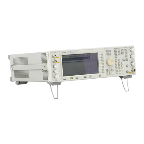
DK-Audio PT 5201 Compact VariTime User manual

DK-AUDIO A/S
Marielundvej 37 D
DK-2730 Herlev
Denmark
PT 5201
Compact VariTimeTM Sync Generator
Operating Manual

PT 5201 Compact VariTimeTM Sync Generator
Copyright 2001 DK-AUDIO A/S, Denmark
All Rights Reserved
Printed: November 2001
Revision: 2
Publication number: 9499 491 02212

PT 5201 PTV Contents
Operating Manual Revision 2
i
1Contents
1CONTENTS...................................................................................................................I
2SAFETY...................................................................................................................2-1
2.1 INTRODUCTION ...................................................................................................2-1
2.2 SAFETY PRECAUTIONS .........................................................................................2-1
2.3 USE OF CAUTION AND WARNING STATEMENTS.........................................................2-1
2.4 IMPAIRED SAFETY PROTECTION.............................................................................2-2
2.5 TECHNICAL SPECIFICATION...................................................................................2-2
2.5.1 EQUIPMENT RATINGS.....................................................................................2-2
2.6 ELECTROSTATIC SENSITIVE DEVICES......................................................................2-3
2.7 SYMBOLS...........................................................................................................2-4
3INTRODUCTION AND APPLICATIONS ......................................................................3-1
3.1 INTRODUCTION ...................................................................................................3-1
3.2 CONFIGURATION .................................................................................................3-1
3.3 APPLICATIONS ....................................................................................................3-2
4PRODUCT DATA.....................................................................................................4-1
4.1 SAFETY CHARACTERISTICS ...................................................................................4-1
4.2 PERFORMANCE CHARACTERISTICS.........................................................................4-1
4.3 SUMMARIZED DATA .............................................................................................4-1
4.3.1 MASTER FREQUENCY REFERENCE TCXO .........................................................4-1
4.3.2 REMOTE CONTROL........................................................................................4-1
4.3.3 ANALOG GENLOCK ........................................................................................4-1
4.3.4 ANALOG BLACK BURST OUTPUTS ....................................................................4-2
4.3.5 VIDEO SIGNAL GENERATOR............................................................................4-2
4.3.6 AES/EBU AUDIO GENERATOR........................................................................4-3
4.3.7 WORDCLOCK (WCLK) GENERATOR.................................................................4-4
4.3.8 ANALOG AUDIO GENERATOR...........................................................................4-4
4.3.9 PRESETS.....................................................................................................4-5
4.4 ENVIRONMENTAL CONDITIONS...............................................................................4-6
4.4.1 REGULATIONS AND STANDARDS.......................................................................4-6
4.4.2 CLIMATIC CONDITIONS ...................................................................................4-6
4.4.3 MECHANICAL REQUIREMENTS .........................................................................4-6
4.4.4 SAFETY .......................................................................................................4-6
4.5 POWER SUPPLY..................................................................................................4-6
4.6 MECHANICAL DATA..............................................................................................4-6
5INSTALLATION........................................................................................................5-1
5.1 ACCESSORIES ....................................................................................................5-1

Contents PTV PT 5201
Revision 2 Operating Manual
ii
5.2 INITIAL INSPECTION..............................................................................................5-1
5.3 SAFETY INSTRUCTION..........................................................................................5-1
5.3.1 GROUNDING .................................................................................................5-1
5.4 MAINS VOLTAGE CORD AND FUSES ........................................................................5-1
5.5 RACK MOUNTING ................................................................................................5-2
5.5.1 RACK MOUNT INSTRUCTIONS ..........................................................................5-2
5.6 ACCESS TO AND REPLACEMENT OF PARTS ..............................................................5-4
6OPERATING INSTRUCTIONS ...................................................................................6-1
6.1 INSTRUMENT DESCRIPTION...................................................................................6-1
6.2 FRONT PANEL.....................................................................................................6-1
6.3 HOW TO GET STARTED ........................................................................................6-2
6.4 REAR PANEL ......................................................................................................6-3
6.5 PC REMOTE CONTROL PROGRAM.........................................................................6-3
6.5.1 APPLICATION DESCRIPTION.............................................................................6-3
6.5.2 MENU DESCRIPTION ......................................................................................6-4
7REMOTE INTERFACE ............................................................................................7-11
7.1 GENERAL DESCRIPTION OF THE INTERFACE SYNTAX...............................................7-11
7.1.1 CONNECTOR DESCRIPTION...........................................................................7-11
7.1.2 PROTOCOL.................................................................................................7-11
7.1.3 CONFIGURATION AND SYNTAX.......................................................................7-12
7.1.4 GENERAL INFORMATION ...............................................................................7-12
7.1.5 SYNTAX ELEMENTS .....................................................................................7-13
7.1.6 COMMAND SYNTAX......................................................................................7-14
7.1.7 SYNTAX OF PROGRAM MESSAGES .................................................................7-14
7.1.8 LONG AND SHORT FORM ..............................................................................7-15
7.1.9 SYNTAX OF RESPONSE MESSAGES ................................................................7-15
8COMMANDS SUMMARY..........................................................................................8-1
8.1 MANDATED COMMANDS........................................................................................8-1
8.2 REQUIRED COMMANDS ........................................................................................8-1
8.2.1 SYSTEM SUBSYSTEM....................................................................................8-1
8.2.2 STATUS SUBSYSTEM ....................................................................................8-2
8.3 INSTRUMENT COMMANDS .....................................................................................8-2
8.3.1 INPUT SUBSYSTEM .......................................................................................8-2
8.3.2 OUTPUT SUBSYSTEM....................................................................................8-2
9COMMANDS EXPLANATION....................................................................................9-1
9.1 MANDATED COMMANDS........................................................................................9-1
9.2 REQUIRED COMMANDS ........................................................................................9-2
9.2.1 SYSTEM COMMANDS ....................................................................................9-2
9.2.2 STATUS COMMANDS .....................................................................................9-3
9.3 INSTRUMENT COMMANDS .....................................................................................9-4
9.3.1 INPUT COMMANDS ........................................................................................9-4
9.3.2 OUTPUT COMMANDS ....................................................................................9-5
10 ERROR CODES.....................................................................................................10-1

PT 5201 PTV Contents
Operating Manual Revision 2
iii
10.1 COMMAND ERRORS [-199, -100] .........................................................................10-1
10.2 EXECUTION ERRORS [-299, -200]........................................................................10-1
10.3 DEVICE SPECIFIC ERRORS [-399, -300]................................................................10-2
11 PT 5201 SIGNALS...............................................................................................11-1
11.1 VIDEO PATTERNS..............................................................................................11-1
11.2 PATTERN SELECTIONS AFTER SYSTEM CHANGE.....................................................11-2
11.3 AUDIO SIGNALS ................................................................................................11-2
11.4 RESET CONFIGURATION.....................................................................................11-4


PT 5201 PTV Safety
Operating Manual Revision 2
2
-
1
2Safety
Read this chapter carefully before installation and use of the instrument.
2.1 Introduction
The instrument described in this manual is designed to be used by properly trained personal
only.
Only qualified personnel who are aware of hazards involved shall carry out adjustment,
maintenance and repair of the exposed equipment.
2.2 Safety Precautions
For the correct and safe use of the instrument, it is essential that both operating and servicing
personnel follow generally accepted safety procedures in addition to the safety precautions
specified in this manual. Specific warning and caution statements, where applicable, are found
throughout this manual.
Warning and caution statements and/or symbols are marked on the instrument as well.
Special attention must be paid to the following issues:
♦Protective grounding of the instrument is required for the accessible terminals to be safe.
(IEC 1010-1 Safety class I instrument)
♦The actual environmental conditions must be checked against the specification.
♦Mains voltage must be inside the specified range.
The opening of covers or removal of parts, except those to which access can be gained by
hand, is liable to expose live parts and terminals.
If adjustment, maintenance, or repair of the opened instrument is unavoidable, only a skilled
person who is aware of the hazards involved must carry it out.
2.3 Use of Caution and Warning Statements
Caution
Used to indicate correct operation or maintenance in order to prevent damage to, or destruction
of equipment or other property.
Warning
Used to indicate a potential hazard that requires correct procedures or practices in order to
prevent personal injury.

Safety PTV PT 5201
Revision 2 Operating Manual
2-2
2.4 Impaired Safety Protection
Whenever it is likely that safe operation is impaired, the instrument must be made inoperative
and secured against unintended operation. The appropriate servicing authority must be
informed.
For example, safety is likely to be impaired if the instrument fails to perform the intended
functions or shows visible damage.
The instrument is NOT equipped with a mains interruption switch, and thus to be made
inoperative by unplugging its mains connection lead, or by other means prior of the instrument
WARNING: Protection provided by the equipment may be impaired if the equipment is used in a
manner not specified by this manual.
2.5 Technical Specification
This manual provides technical information important for safe operation of the equipment.
Please refer to chapter 4Product Data for information regarding technical specifications and to
chapter 5Installation and chapter 6Operating Instructions regarding instructions for use.
Technical assistance may be obtained from your local PTV customer support organization or
from:
DK-Audio
Marielundvej 37D
DK-2730 Herlev
Denmark
Phone: +45 44 85 02 55
Fax: +45 44 85 02 50
Website: http://www.ptv.dk and http://www.DK-Audio.com
2.5.1 Equipment Ratings
The instrument can be used with a mains voltage supply of:
Voltage:
90-250 VAC
Frequency:
47-63 Hz
The power Consumption:
Does not exceed 25 Watts.
The instrument is designed for the following environmental conditions:
Indoor use

PT 5201 PTV Safety
Operating Manual Revision 2
2
-
3
Altitudes up to 2000m
Temperatures between 5°C and 45°C
Maximum relative humidity of 80% for temperatures up to 31°C decreasing linearly to 50%
relative humidity at 40°C.
The instrument is equipped with a number of input and output terminals as described in chapter
4Product Data.
The terminals are protected from becoming live by means of basic insulation and protective
screening.
Whenever it is likely that safe operation is impaired, the instrument must be made inoperative
and secured against unintended operation. The appropriate servicing authority must be
informed.
For example, safety is likely to be impaired if the instrument fails to perform the intended
operations or shows visible damages.
2.6 Electrostatic Sensitive Devices
All IC and many other semi-conductors are susceptible to electrostatic discharges (ESD).
Careless handling during repair can reduce lifetime drastically.
When repairing, make sure that you are connected to the same potential as the mass of the set
via a wrist wrap with resistance. Keep component and tools at this potential.

Safety PTV PT 5201
Revision 2 Operating Manual
2-4
2.7 Symbols
Symbol Explanation:
Caution, risk of electric shock.
Caution (refer to accompanying documents)
Protective conductor terminal.
~
Alternating current

PT 5201 PTV Introduction and Applications
Operating Manual Revision 2
3
-
1
3Introduction and Applications
3.1 Introduction
The PT 5201 Compact VariTimeTM Sync Generator includes all basic features for professional
sync, timing and test signals in one half-sized box.
The new digital studios need cost efficient and reliable synchronization for the main equipment
to work reliably. For this purpose PTV offers the PT 5201 as the fully integrated solution
eliminating any costs associated with modular structures, support of many different signal types
and extensive operating facilities.
Analog Black Burst is still routinely used for timing purposes, also in digital installations, where
processing delays are often on the order of several fields.
The PT 5201 Compact VariTimeTM Sync Generator is designed with the multiple delays of digital
television installations in mind, but also fulfils all synchronization requirements when used with a
combination of digital and traditional analog video systems.
The PT 5201 Compact VariTimeTM Sync Generator is a multi-standard sync generator and
provides sync and test signals for both NTSC, PAL and for SDI outputs of 525/59.94 and 625/50
systems.
Each of the reference Black Burst outputs and the Test Signal Generator output can be
individually selected in system (NTSC/PAL) and timed in fine steps over the complete
sequence.
The serial digital black and test signals can be timed with a resolution of 37 ns over a ±1 field
range.
The analog black bursts are timeable in sub-nanosecond resolution over a ±4 fields sequence
for PAL and ±2 fields sequence for NTSC.
The timing of analog Test Signal Generator follows the timing of the SDI generator, i.e. with a
37ns resolution but over a ±4 fields sequence for PAL and ±2 fields sequence for NTSC.
3.2 Configuration
The operation of PT 5201 Compact VariTimeTM Sync Generator is based on a PC Remote
Control. The PC Remote Control program makes it easy to manage all timing, patterns and
audio features in one screen.
The settings for the PC Remote Control are either loaded from the PC or downloaded from the
generator. When the settings are loaded from the PC the data is transferred immediately to the
generator, overwriting the actual state.
At exit from the panel, data is stored in a file on the PC for later use.
Four presets can be stored in the instrument and also in 4 separate files on the PC. Any preset
can then be recalled either from the PC or from the generators internal memory.
The hidden button on the front plate can select the stored presets in the generator.
Communication between PT 5201 and PC via standard RS-232 protocol makes it possible to
use any kind of PC.
Status of current functions and systems will be displayed at any time corresponding to the
LED’s on the PT 5201 front panel.

Introduction and Applications PTV PT 5201
Revision 2 Operating Manual
3-2
3.3 Applications
The PT 5201 is designed to manage slave as well as master operations as a stand-alone unit.
In systems where PT 5201 operates as a master the reference is locked to an internal, high
stability TCXO oscillator (Temperature Compensated Xtal Oscillator)
For use in slave applications the genlock function is used.
The genlock function features genlock to NTSC and PAL video signals, Black Burst house sync
or a 10 MHz reference clock, e.g. from a GPS receiver. The genlock function features passive
loop-through, and has a common timing facility for the generator.

PT 5201 PTV Product Data
Operating Manual Revision 2
4
-
1
4Product Data
4.1 Safety Characteristics
This apparatus has been designed and tested in accordance with the safety Class I
requirements of the IEC publication 1010-1 (“Safety Requirements for Electrical Measuring
Apparatus”), and is safe as supplied. This manual contains information and warnings, which
must be followed during operation to ensure operator and service personnel safety.
4.2 Performance Characteristics
Characteristics expressed in numerical values with stated tolerances are guaranteed tolerances,
when the instrument is calibrated at 25°C and after 20-min. warm-up. Specified numerical data
without tolerances indicate typical values at nominal ambient temperature (25°C) and reflects an
average performance.
4.3 Summarized Data
The instrument has been developed based on the latest, relevant ITU, SMPTE, EBU, and
AES/EBU specifications.
4.3.1 Master Frequency Reference TCXO
Temperature drift: ±2.5 ppm (0-50oC, ref. 25oC)
Ageing:±1 ppm/year; first year then better
4.3.2 Remote Control
Input Interface: RS-232 port, 9 pole D-sub, male
Protocol: SCPI based
Baud rate. 9600 kbit
4.3.3 Analog Genlock
Input: 75 Ωlooped through
Return loss: >36 dB to 6 MHz
4.3.3.1 Genlock Signal (M-NTSC or G-PAL)
Amplitude: Nominally ± 3 dB
S/N ratio: >26 dB
Input Sc-H phase: Nominally ±45o
Pull-in range fsc:± 50 Hz
Jitter when locked to burst: < 0.5o
Jitter when locked to sync: < 5 ns

Product Data PTV PT 5201
Revision 2 Operating Manual
4-2
4.3.3.2 Timing Facilities
Timing range: PAL: ±4 fields
NTSC: ±2 fields
Timing resolution: 0.5oat fSC
4.3.3.3 Timing Resolution
Analog Black Burst: 0.15 ns
Video, analog and digital: 37 ns
4.3.3.4 Genlock Signal (Continuous frequency)
Continuous frequency reference: 10 MHz
Amplitude:1 V ±3 dB
4.3.4 Analog Black Burst Outputs
Connector: BNC
Output impedance: 75 Ω±0.5 Ω
Return loss: >36 dB, to 5 MHz
Sync amplitude: PAL: -300mV ±2%
NTSC: -286mV ±2%
Burst amplitude: PAL: 300mV ±2%
NTSC: 286mV ±2%
Timing range: PAL: ±4 fields
NTSC: ±2 fields
Timing resolution: 0.5oat fsc
Sc-H phase: Default 0o, adjustment ± 180o, resolution <1o°
S/N ratio: 60 dB unweighted to 5 MHz
4.3.5 Video Signal Generator
4.3.5.1 SDI Output
Connector: BNC
Output impedance: 75 Ω±0.5 Ω
Format: 270 Mb/s serial, complies with ITU-R BT 656 and SMPTE
259 M
Return loss: >15 dB, 5 –270 MHz
Timing range: PAL: ±1 field
NTSC: ±1 field
Timing resolution: 37 ns
Jitter: < 0,20 UI
Rise and fall time: 0.75 –1.50 ns
Embedded Audio: 1kHz stereo, silence and off
4.3.5.2 Analog Output
This output is primarily for testing purposes, as its color phasing is unlocked to the Black Burst
outputs.
Connector: BNC
Output impedance: 75 Ω±0.5 Ω

PT 5201 PTV Product Data
Operating Manual Revision 2
4
-
3
Return loss: >36 dB, to 5 MHz
Sync amplitude: PAL: -300 mV ±2%
NTSC: -286 mV ±2%
Burst amplitude: PAL: 300 mV ±2%
NTSC: 286 mV ±2%
Video accuracy: Nominal ±2 %
Timing range: PAL: ±1 fields
NTSC: ±1 fields
Timing resolution: 37 ns,
Sc-H phase: Default 0o, adjustment ± 180o, resolution: 1.4o
S/N ratio: 50 dB unweighted to 5 MHz
4.3.5.3 Common Test Signals, SDI and Analog Generator
All signals are in standard 4x3 aspect ratio.
Patterns dedicated for PAL: EBU Color Bar
75% Color Bar + red
CCIR Line 18
Patterns dedicated for NTSC: SMPTE Color Bar
FCC Color Bar
Patterns common for NTSC/PAL: Color Bar ITU801
Color Bar 100%
75% Red
Crosshatch
PLUGE
SDI Check Field
Digital Grey
Staircase 5 step
Staircase 10 step
15 KHz Bl/Wh
White 100%
Black
Window 10%
Window 15%
Window 20%
Window 100%
4.3.6 AES/EBU Audio Generator
Serial digital audio generator with test tones.
Connector: XLR
Output format: Balanced 110 Ω±20% According to AES3 1992
Amplitude: 3VPP Typically
Data bitrate: 3.072 Mbit/s
Rise and fall time: 5-30 ns
Coding: Linear, 20-bits two’s complement binary biphase mark

Product Data PTV PT 5201
Revision 2 Operating Manual
4-4
Pre-emphasis: None
Timing: +10.4 µs to -9.6 µs in 0.8 µs steps
4.3.6.1 AES/EBU Output Signals
Tones: Stereo 500 Hz
Stereo 1 kHz
Stereo EBU 1 kHz, single click in ch. A
Stereo 8 kHz
Click rate: 1 or 3 s.
Levels: Silence
0 dBFS
-9 dBFS
-12dBFS
-15 dBFS
-16 dBFS
-18 dBFS
-20 dBFS
4.3.7 Wordclock (WCLK) Generator
Connector: BNC
Output impedance: 75 Ω±0.5 Ω
Output characteristics: HC-MOS clock, 0 –5 V un-terminated
Reference output: 44.1 or 48 kHz
The 48 kHz is frequency and phase locked to the video.
The 44.1kHz is the CD audio sample frequency and frequency locked to the video frequency
4.3.8 Analog Audio Generator
Connector: XLR
Output format: Balanced 30 Ω
Balanced by active circuitry.
Reference amplitude: 0 dBu, corresponding to 775 mV
Distortion: < 1 %
4.3.8.1 Analog Audio Output Signals
Tones: Stereo 500 Hz
Stereo 1 kHz
Stereo EBU 1 kHz, single click in ch. A
Stereo 8 kHz
Click rate: 1 or 3 s.

PT 5201 PTV Product Data
Operating Manual Revision 2
4
-
5
Levels: +10 dBu
+8 dBu
+7 dBu
+6 dBu
+5 dBu
+4 dBu
+3 dBu
+2 dBu
+1 dBu
0 dBu
-1 dBu
-2 dBu
-3 dBu
-4 dBu
-5 dBu
-6 dBu
-7 dBu
-8 dBu
-9 dBu
-10 dBu
-11 dBu
-12 dBu
-13 dBu
-15 dBu
-18 dBu
-20 dBu
-24 dBu
-27 dBu
-30 dBu
-33 dBu
-36 dBu
Silence
4.3.9 Presets
Four preset set-ups can be stored in the unit. Besides essential data for the individual Presets
all user accessible parameters for the outputs are included and stored in non-volatile memory.
The Presets are named Preset 1 –4 in the unit.
In the PC Remote Control each preset is identified by:
Name (24 characters, no space)
Author
Date of modification
The preset name is displayed in the Preset Status box in the System Status window, when the
preset is active.
The front panel LEDs using the hidden Preset button also displays preset status. See operation
instructions.

Product Data PTV PT 5201
Revision 2 Operating Manual
4-6
4.4 Environmental Conditions
4.4.1 Regulations and Standards
♦EN 50081-1/1992 (emissions)
♦EN 50082-1/1992 (immunity)
4.4.2 Climatic Conditions
Temperature range:
Storage: -30o-+70oC (41oF –113oF)
Ambient operating: +5o-+45oC (-22oF -+158oF)
Humidity: Non condensing (IEC 721)
4.4.3 Mechanical Requirements
Vibration:
Limit range for storage and transport:
30 min. in each of three directions, 10 to 150 Hz; 0.7 mmp-pand 50 m/s2max acceleration.
According to IEC-Publ. 68, test Fc.
NOTE:
Unit mounted on vibration table without shock absorbing material.
Bump:
Limit range for storage and transport:
1000 bumps of 100 m/s2sine, 6 ms duration in each of 3 directions.
According to IEC-Publ. 68, test Eb.
4.4.4 Safety
Comply to IEC1010-1
4.5 Power Supply
Voltage: 90 -250 VAC
Frequency: 47 -63 Hz
Power consumption: 22 W
4.6 Mechanical Data
Mechanical data for cabinet
Height: 42 mm (1.66")
Width: 217 mm (8.54")
Depth: 380 mm (15")
Weight: 1.5 kg (3.3 lbs)
Mechanical data for cabinet fitted with 19" rack mount
Height: 44 mm (1.73")
Width: 442 mm (18.4")
Depth: 380 mm (15")
Weight: 2.3 kg (5.1 lbs)

PT 5201 PTV Product Data
Operating Manual Revision 2
4
-
7
Mechanical data for two cabinets side by side, fitted with 19" rack mount
Height: 44 mm (1.73")
Width: 442 mm (18.4")
Depth: 380 mm (15")
Weight: 3.8 kg (8.4 lbs)

Table of contents
Popular Portable Generator manuals by other brands
Selecta Power
Selecta Power MANLBA-105 Operator's manual

Coleman
Coleman Powermate PM Series Operator's manual
Briggs & Stratton
Briggs & Stratton 030670-00 manual

EINHELL
EINHELL Superior 5000 DD operating instructions

Krüger Technology
Krüger Technology KGVC3000 instruction manual

Firman
Firman H07553 Operator's manual
Westinghouse
Westinghouse WGen12000 user manual
Team Orion
Team Orion dDrive instruction manual
Mase
Mase IS 9.6 Use, maintenance and installation manual

Champion Power Equipment
Champion Power Equipment C75520 user manual
Bosch
Bosch Rexroth CytroPac operating instructions

Champion
Champion 100304 Operator's manual

