DK-Technologies PT5300 Instruction Manual

PT5300
MasterSyncGenerator
Guide to Installation and Operation
[Software version: 6.6 Sep 2014]
DK-Technologies

2 | PT5300
SAFETYCOMPLIANCE
This equipment complies with:
EN 60950-1 (2nd edition) directive 2006/95/EC
CSA C22.2 No. 60950-1 (2nd edition)
UL 60950-1 (2nd edition)
The power cord supplied with this equipment meets the appropriate national standards for the country
of destination.
WARNING An appropriately listed/certified mains supply power cord must be used for the connection of the
equipment to the mains voltage at either 120V~ or 240V~. The socket-outlet shall be installed near
the equipment and shall be easily accessible.
Protective grounding of the instrument is required for the accessible terminals to be safe (EN
60950-1).
CAUTION This equipment is meant to be installed in a restricted-access location.
Disconnect power cord before servicing.
These servicing instructions are for use by qualified service personnel only.
To reduce the risk of electric shock, do not perform any servicing other than that contained in the
operating instructions unless you are qualified to do so. Refer all servicing to qualified service personnel.
ELECTROMAGNETICCOMPATIBILITY
This equipment has been tested for verification of compliance with FCC Part 15, Subpart B requirements for
Class A digital devices.
NOTE: This equipment has been tested and found to comply with the limits for a Class A digital device, pursuant to
part 15 of the FCC Rules. These limits are designed to provide reasonable protection against harmful interference
when the equipment is operated in a commercial environment. This equipment generates, uses, and can radiate
radio frequency energy and, if not installed and used in accordance with the instruction manual, may cause harmful
interference to radio communications. Operation of this equipment in a residential area is likely to cause harmful
interference in which case the user will be required to correct the interference at his own expense.
This equipment has been tested and found to comply with the requirements of the EMC directive
2004/108/CE:
•EN 55022 / EN 55016-2-3 / EN 55014-1 Emissions
•
EN 55103-2 Annex A and B Immunity
•
EN 61000-3-2 Harmonic current emission limits
•
EN 61000-3-3 Limitation of voltage changes, voltage fluctuations and flicker
•
EN 61000-4-2 Electrostatic discharge immunity
•
EN 61000-4-3 Radiated electromagnetic field immunity –radio frequencies
•
EN 61000-4-4 Electrical fast transient immunity
•
EN 61000-4-5 Surge immunity
•
EN 61000-4-6 Conducted emissions immunity
•
EN 61000-4-11 Voltage dips, short interruptions and voltage variations immunity
Disposal and Recycling information

PT5300 | 3
Batteries:
Your DK-Technologies PT5300 comes with at least one lithium carbon monofluoride battery (Li-CFx) located on the
main
printed circuit board. The PT8616 GPS option card comes with at least one manganese lithium battery
(LiMn2O4). The batteries are used for backup and should not need to be replaced during the lifetime of the equipment.
Before disposing of your DK-Technologies equipment, please remove all batteries
as follows:
1
Make sure the AC power cord is unplugged from the power outlet;
2
Remove the protective cover from your equipment;
3
Gently remove each battery from its casing, using a blunt instrument such as a screwdriver for leverage if
necessary.
4
Dispose of the batteries and equipment according to your local environmental laws and guidelines
WARNING
Be careful not to short-circuit the batteries - adhere to the appropriate ESD practices. Do not dispose of batteries in a
fire as they may explode. Batteries may explode if damaged or overheated. Do not dispose of batteries as household
waste. Do not dismantle, open or shred batteries. Keep batteries out of the reach of children. In the event of a battery
leak, do not allow battery liquid to come in contact with skin or eyes. Seek medical help immediately in case of
ingestion, inhalation, skin or eye contact, or suspected exposure to the contents of an opened battery.
For more information about recycling, please contact DK-Technologies
Technologies.

4 | PT5300
Table of Contents
1PT5300 Master Sync Generator.............................................................................................................1
1.1 Introduction..........................................................................................................................................................1
1.2 Applications.........................................................................................................................................................1
2Product Data...........................................................................................................................................3
2.1 Performance Characteristics...............................................................................................................................3
2.2 Versions...............................................................................................................................................................3
2.3 Options................................................................................................................................................................3
2.4 Basic Instrument –Description and Technical Specifications..............................................................................4
2.4.1 Master Frequency Reference.................................................................................................................4
2.4.2 Analog Genlock......................................................................................................................................4
2.4.3 Genlock Signal (M-NTSC or G-PAL)......................................................................................................4
2.4.4 Genlock Signal.......................................................................................................................................4
2.4.5 Analog Genlock Transparent Channel....................................................................................................4
2.4.6 Analog Black Burst Outputs ...................................................................................................................4
2.5 Communication interface.....................................................................................................................................5
2.6 Changeover Control............................................................................................................................................5
2.7 Presets................................................................................................................................................................5
2.8 Options –Description and Technical Specifications............................................................................................5
2.8.1 PT8608 Dual Black Burst Generator......................................................................................................5
2.8.2 PT8611 Quad HD Tri-Level Sync Generator..........................................................................................6
2.8.3 PT8635 Dual AES/EBU Audio Generator...............................................................................................7
2.8.4 PT8612 Quad HD-SD Serial Digital Test Signal Generator....................................................................7
2.8.5 PT8616 GPS Genlock and LTC Generator & VITC decoder (PT8620)..................................................9
2.8.6 Ethernet port and PT8643 SNTPv4 Time Server Option......................................................................10
2.8.7 Level detectors.....................................................................................................................................10
2.9 Mechanical and Environmental Specification....................................................................................................11
2.9.1 Climate Conditions...............................................................................................................................11
2.9.2 Mechanical Requirements....................................................................................................................11
2.10 Power Supply....................................................................................................................................................11
2.11 Mechanical Data................................................................................................................................................11
3Installation............................................................................................................................................12
3.1 Initial Inspection.................................................................................................................................................12
3.2 Safety Instruction...............................................................................................................................................12
3.2.1 Grounding.............................................................................................................................................12
3.2.2 Mains Voltage Cord and Fuses ............................................................................................................12
3.3 Rack Mounting ..................................................................................................................................................13
3.4 Cleaning............................................................................................................................................................13
3.5 GPS Antenna and cable connection..................................................................................................................14
4Operating Instructions.........................................................................................................................15
4.1 General Information...........................................................................................................................................15
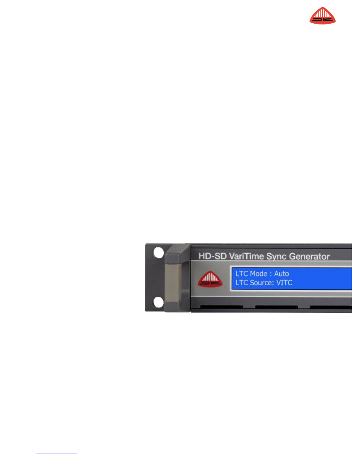
4.2 Front Panel Controls .........................................................................................................................................15
4.2.1 Navigation Keypad...............................................................................................................................15
4.3 Indicators and Connections...............................................................................................................................16
4.3.1 Front Panel Indicators..........................................................................................................................16
4.4 Display Information............................................................................................................................................16
4.5 Rear Panel Connections ...................................................................................................................................17

PT5300 | 5
4.6 Panel Operation ................................................................................................................................................18
4.6.1 Power Up .............................................................................................................................................19
4.6.2 Status Displays.....................................................................................................................................19
4.6.3 Menu Operation....................................................................................................................................20
4.7 Detailed Description of Menus...........................................................................................................................21
4.7.1 Menu: BLACK-BURST generator.........................................................................................................21
4.7.2 Menu: TRI-LEVEL sync generator .......................................................................................................23
4.7.3 Menu: GENLOCK.................................................................................................................................25
4.7.4 Menu: GPS Genlock and LTC output...................................................................................................28
4.7.5 Menu: NETWORK................................................................................................................................31
4.7.6 Menu: PRESET....................................................................................................................................35
4.7.7 Menu: CONFIG ....................................................................................................................................37
4.7.8 Menu: HD & SD-SDI, Serial Digital Test Signal Generator...................................................................39
4.7.9 Menu: AES-EBU, Dual AES/EBU Digital Audio Generator...................................................................45
4.8 Reset.................................................................................................................................................................47
4.8.1 Factory Reset.......................................................................................................................................47
4.8.2 Menu: CONFIG/DIAGNOSE ................................................................................................................47
5Remote Interface..................................................................................................................................54
5.1 General Information...........................................................................................................................................54
5.2 Serial Remote....................................................................................................................................................54
5.3 Telnet Remote –User Name and Password.....................................................................................................55
5.4 General Description of the Interface Syntax......................................................................................................55
5.4.1 General Information..............................................................................................................................55
5.4.2 Syntax Elements ..................................................................................................................................56
5.4.3 Command Syntax.................................................................................................................................56
5.4.4 Syntax of Program Messages ..............................................................................................................56
5.4.5 Long and Short Form...........................................................................................................................57
5.4.6 Syntax of Response Messages............................................................................................................57
6Command reference.............................................................................................................................58
6.1 Reference Documents.......................................................................................................................................58
6.2 Configuration and Syntax..................................................................................................................................58
6.3 Commands Summary........................................................................................................................................58
6.3.1 Mandated Commands..........................................................................................................................58
6.3.2 Instrument Commands.........................................................................................................................59
6.4 Commands Explanation....................................................................................................................................62
6.4.1 Mandated Commands..........................................................................................................................62
6.4.2 Required Commands ...........................................................................................................................63
6.4.3 Instrument Commands.........................................................................................................................65
6.5 Communication Error Codes.............................................................................................................................79
6.5.1 Command Errors [-199, -100]...............................................................................................................79
6.5.2 Execution Errors [-299, -200]................................................................................................................81
6.5.3 Device specific Errors [-399, -300].......................................................................................................81
6.5.4 Query Errors [-499, -400]......................................................................................................................82
7Error & Message Codes.......................................................................................................................83


PT5300 | 1
1 PT5300 Master Sync Generator
1.1 Introduction
The PT5300 HD-SD Master Sync Generator is specially designed to fit into HD as well as SD digital and mixed
digital/analog video installations, and it provides signals for synchronization, fault finding and checking of the entire
digital chain. Because of its many parallel outputs, the PT5300 is ideal for supplying the video production facility
with
all commonly-used test signals for alignment, but also generates -bypatterns.
The basic generator is available as an SD or HD-SD gen-lockable sync with 2 Black Burst outputs. In the HD-SD
version it has furthermore 4 Tri-Level sync outputs available. A dual AES/EBU digital audio generator is also included
in the base units.
The DK-Technologies PT5300 can be assembled at the factory with a number of optional modules that tailor it to specific
applications.
Up to two Quad Test Signal generators can be added to the basic unit, making up to 8 different HD or SD SDI test
signals with audio tones available at a time. The HD-SD SDI generator is switchable between 625 and 525 lines and
the various HD formats, and can superimpose three lines of text on the video signals. With complex test patterns, the
text is automatically placed in black text fields.
The PT5300 is gen-lockable to a traditional Black Burst signal, but can also be locked onto a 5MHz or 10MHz
continuous wave. It can even lock onto a 525-line video signal and still generate PAL, 625-line SD-SDI signals and
HD SDI signals in the major parts of formats.
Each of the outputs can be individually timed: SD-SDI signals can be timed in steps of 37 ns over a ±1 field range;
HD-SDI and Tri-Level Sync signals in steps of 6.7 ns, the analog Black Bursts and test pattern outputs are timeable
in steps of 0.5◦of subcarrier over a ±4 field sequence for PALand ±2 field sequence for NTSC.
The stability of the internal reference oscillator ensures accurate signals when the PT5300 is acting as a standalone
reference generator.
AES/EBU digital audio is available on both XLR and BNC connectors. The generator module has two built-in
generators, which can be programmed independently with silence or with tones that include signals with audible
left/right indication. TheAES/EBU output signals are always locked both to the 525-line and 625-line outputs. In multi-
standard operations, this permits direct connection betweenAES/EBU generators in 525-line and 625-line
environments.Aseparate word-clock signal is available on a BNC connector.
1.2 Applications
The PT5300 can be used in a multitude of different applications, e.g. delivering signals for a video switcher, as a
master
and as backup Sync Pulse Generator (SPG) and as a general video signal generator.
In small studios and in OB-vans it can work as an SPG while also delivering test signals at the same time. It also
operates in dual redundant configurations when used with an PT5211 Changeover Unit. Built-in fault detection
circuitry automatically switches from main to backup to keep disruptions to a minimum.
In digital distribution networks where data compression is used, a stationary test signal will not reveal if the line is in a
“freeze” mode.A moving bar added to the standby pattern will show if the line is open and if the time and date
appears in the pattern, this is a good indication that the line is not frozen.

2 | PT5300
The time information can be locked onto VITC, LTC, or the internal video reference. The time can be offset to cope
with delays in distribution, MPEG-2 coding and transmission. It also ensures that the “true” time can be displayed at
the reception point.
Six complete instrument presets have been included to enable quick changes in operation mode. Each of the set-ups
may be given names with a string of up to a 16 character.
In automated applications, the RS232 remote control interface provides full control over all functions of the generator.
Parameters for each output can be adjusted remotely and a complete set-up can be transmitted to and from the
instrument.
A Telnet (Ethernet) interface is also available. As with the RS232 interface, the Telnet interface provides full control
over all functions of the generator.With the limitation that complete presets cannot currently be transmitted through
Telnet, the commands and responses are the same as with the RS232 interface.

PT5300 | 3
2 Product Data
2.1 Performance Characteristics
Characteristics expressed in numerical values with stated tolerances are guaranteed tolerances, when the instrument
is calibrated at 20-30◦C and after 20 min. warm-up. Specified non-tolerance numerical data indicate typical values at
nominal ambient temperature (25◦C) and reflects an average performance.
2.2 Versions
The generator is based on two basic versions, one for SD-SDI and analog applications and one for HD-SD SDI and
analog applications. The HD SD version includes the Tri-level Sync option (PT8611). Both versions are gen-
lockable sync pulse generators with further 2 x Black Burst outputs as well. Both versions also include a dual
AES/EBU audio generator. To the basic configuration a number of units can be added.
The apparatus is a multi-format, simultaneously covering SD-SDI (625/525), analog PAL and analog NTSC and the
extended version with additional HD Tri-level sync outputs as well as HD-SDI test signal outputs.
The HD SD-SDI generator works in 16 different HD formats plus the SD-SDI formats 625 and 525 lines, where the Tri-
Level sync option (PT8611) works with 20 different HD formats.
2.3 Options
Option Name
Function
Part Number
PT8608
Dual Black Burst Generator
9449 086 08001
PT8611*
Quad HD Tri-Level Sync Generator
9449 086 11001
PT8612
Quad HD-SD SDI TestSignal Generator
9449 086 12001
PT8616
GPS Genlock and LTC Generator (PT8620)
9449 086 16001
PT8635*
DualAES/EBU Audio Generator
9449 086 35001
PT8643
SNTP server module
9449 086 43001
PT8620**
LTC generator and VITC decoder
9449 086 20001
* NB –although they appear in the “Options” list, the Quad Tri-Level HDTV Sync Generator (option PT8611) is
included as standard equipment in the 5300HD, and the DualAES/EBU Audio Generator (option PT8635) is
included as standard equipment in the PT5300SD and the 5300HD.
** NB –although it appears in the “Options” list, LTC generator and VITC decode (option PT8620) is included with
the GPS genlock and LTC generator (option PT8616).

4 | PT5300
2.4 Basic Instrument –Description and Technical Specifications
2.4.1 Master Frequency Reference
27 MHz master frequency: Better than 0.25 ppm (0-50◦C, ref. 25◦C)
Ageing: < 0.1 ppm/month
2.4.2 Analog Genlock
Input: 75 Ωlooped through or two 75 Ωterminated inputs (menu
configurable)
Return loss: > 38 dB to 6 MHz
2.4.3 Genlock Signal (M-NTSC or G-PAL)
Amplitude: Nominally ± 3 dB
S/N ratio: > 26 dB
SCH phase: Nominally ± 45◦
Pull-in range fsc: ± 20 Hz
Jitter when locked to burst: < 0.5◦
Jitter when locked to sync: < 2 ns
Timing range: PAL: ± 4 fields
NTSC: ± 2 fields
Timing resolution: 0.5◦fsc
2.4.4 Genlock Signal
Continuous frequency reference: Subcarrier, 5 or 10 MHz
Amplitude: 1 V ± 3 dB
2.4.5 Analog Genlock Transparent Channel
The analog genlock signal is transferred via anAC-coupled amplifier to a transparent output.
Output impedance: 75 Ω
Return loss: > 36 dB to 6 MHz
2.4.6 Analog Black Burst Outputs
Number of outputs: 2, independently timeable
Connector: BNC
Return loss: 75 Ω± 0.5 Ω
Sync Amplitude: PAL: -300 mV ± 2%
NTSC: -286 mV ± 2%
Burst Amplitude: PAL: -300 mV ± 2%
NTSC: -286 mV ± 2%
Timing range: PAL: ± 4 fields
NTSC: ± 2 fields

PT5300 | 5
Timing resolution: 0.5◦fsc
SCH phase: Default 0◦, adjustment ± 180◦, resolution < 1◦
S/N ratio: 60 dB unweighted to 5 MHz
Jitter: Burst jitter: ± 0.5◦
Sync jitter: ± 0.5 ns (based on design and burst jitter value)
Output monitoring: Continuous of output level with error flag on “Changeover” connector.
Detectors can be disabled
2.5 Communication interface
The PT5300 is equipped with a 9 pole male D-Sub connector which provides RS232 communication to the
instrument. Please see section 7 for more information about remote control of the PT5300.
An Ethernet port provides a Telnet interface for remote control and an optional SNTP v4 Time Server; PT8643. The
SNTP option requires that a PT8616 GPS genlock module is installed.
If both the computer and the PT5300 are configured with a static IP address (and the same Subnet Mask) a
straight-
through or crossover Ethernet cable can be used to connect the computer and the PT5300 directly.
2.6 Changeover Control
A built-in fault detection circuitry determines when to send an error flag to the PT5211 Changeover Unit. The
detector for each output can be disabled internally, so the user can determine which signals will participate in the
automatic switching decision.
2.7 Presets
Six complete instrument presets are stored in a non-volatile memory.
The presets have names consisting of up to 16 letters. The preset name is displayed when the preset is active.
2.8 Options –Description and Technical Specifications
2.8.1 PT8608 Dual Black Burst Generator
NB –These specifications also apply to the built-in Dual Black Burst generator
2 Black Burst generators individually configurable to PALor NTSC
Number of outputs: 2 with independent timeable outputs
Connectors: 2 x BNC
Output Impedance: 75 Ω± 0.5 Ω
Return loss: > 36 dB, up to 5 MHz
Sync Amplitude: 300 mV ± 2%, (PAL), 286 mV ± 2%, (NTSC)
Burst Amplitude: 300 mV ± 2%, (PAL), 286 mV ± 2%, (NTSC)
Timing range: ± 4 fields (PAL), ± 2 fields (NTSC)
Timing resolution: 0.5◦of subcarrier
SCH phase: Default 0◦, adjustment ± 180◦, resolution < 1◦
S/N ratio: Better than 60 dB unweighted to 5 MHz
Jitter: < ± 0.5 ns

6 | PT5300
2.8.2 PT8611 Quad HD Tri-Level Sync Generator
NB - One card installed in base PT5300HD
Four generators individually configurable to 20 HD Tri-Level Sync formats.
Number of outputs: 4 with independent timeable outputs
HD Formats: 720p, 1080i, 1080p. Frame rates as listed in table 1
Format
Tri-LevelSync
Gen-lock to BB/SDI
1080p/60
x
HD 1080p
1080p/59.94
x
1080p/50
x
1080p/30
x
1080p/29.97
x
x
1080p/25
x
x
1080p/24
x
1080p/23.98
x
1080i/30
x
HD 1080i
1080i/29.97
x
x
1080i/25
x
x
1080sF/30
x
HD 1080sF
1080sF/29.97
x
x
1080sF/25
x
x
1080sF/24
x
1080sF/23.98
x
720p/60
x
HD 720p
720p/59.94
x
x
720p/50
x
x
720p/30
x
720p/29.97
x
x
720p/25
x
x
720p/24
x
720p/23.98
x
576i/25 (625)
x
SD
487i/29.97(525)
x
Table 1: HD Tri-Level sync formats supported byPT5300HD
Connectors: 4 x BNC
Output Impedance: 75 Ω
Return loss: > 30 dB, 5 to 30 MHz
Amplitude: 600 mVpp ± 2%
Jitter: < ± 2%

PT5300 | 7
2.8.3 PT8635 Dual AES/EBU Audio Generator
NB –One card installed in all PT5300SD and PT5300HD generators
Outputs: 2 xAES/EBU pairs
Sampling frequency: 48 KHz
Data rate: 3.072 MBit/s
Type of outputs (Configurable): Silence, tone or word-clock
Linear coding: PCM, 20 bit two’s complement binary, bi-phase mark coding
Single ended outputs: BNC, according to AES3 ID
Output Impedance: 75 Ω± 20%
Amplitude: 1.0 V ± 10%
Rise and fall time: 30-44 ns
Balanced outputs: XLR, according to AES3 1992
Output Impedance: 110 Ω± 20%
Amplitude: 3Vpp typical
Rise and fall time: 10-30 ns
Jitter: < 20 ns
Word clock output: Single ended, BNC
Output Impedance: 75 Ω
Amplitude: 2.5 Vpp in 75 Ω
Outputsignals:
•
Stereo 800Hz, No click
•
Stereo 1 kHz, No click
•
Stereo EBU 1 kHz, Single click in Ch.A
•
Stereo BBC 1 kHz, Single click in Ch. A and double click in Ch. B
•
Mono EBU 1 kHz, Single click in both Ch. A and Ch. B
•
Mono, No click
•
Dual, 1 kHz in Ch.A, 400 Hz in Ch. B, No Click
•
48 KHz reference
Output levels: Silence, 0, -9, -12, -15, -16, -18, -20 dBFS
Pre-emphasis: None
Audio reference word clock output: 48 KHz squarewave
Note: When the 110 ΩXLR output is used with the 48 kHz clock signal, it should be terminated by 110 Ωin order
to obtain reliable transmission.
2.8.4 PT8612 Quad HD-SD Serial Digital Test Signal Generator
Four generators individually configurable with HD and SD test signals.
Number of outputs: 4 with independent timeable outputs
HD Formats: 720p, 1080i, 1080p. Frame rates as listed in table 2
Signals:
•
Video: EBU Color Bar, 75% with 100% white; Color Bar, 100%, with 100% white; SDIcheckfield; PLUGE;
window signals; clapper board; luminance ramp; combination pattern with selectable color bar - white
ramp - LIP SYNC - 75% red; Black, full field; white, full field from -5% to 105% in 5% increments; white,
window from 5% to 105% in 5% increments; cross hatch, 16 x 9
•
Text: Moving text string with up to 3 lines of 16 characters each line inserted in the test signals
•
Audio: Test-tones embedded in the HD-SD SDI signals.

8 | PT5300
Format
Tri-LevelSync
Gen-lock to BB/SDI
1080p/60
x
HD 1080p
1080p/59.94
x
1080p/50
x
1080p/30
x
1080p/29.97
x
x
1080p/25
x
x
1080p/24
x
1080p/23.98
x
1080i/30
x
HD 1080i
1080i/29.97
x
x
1080i/25
x
x
1080sF/30
x
HD 1080sF
1080sF/29.97
x
x
1080sF/25
x
x
1080sF/24
x
1080sF/23.98
x
720p/60
x
HD 720p
720p/59.94
x
x
720p/50
x
x
720p/30
x
720p/29.97
x
x
720p/25
x
x
720p/24
x
720p/23.98
x
576i/25 (625)
x
SD
487i/29.97(525)
x
Table 2: HD-SD serial digital test signals supported by PT5300HD
Connectors: 4 x BNC
Output Impedance: 75 Ω±1%
Return loss: > 15 dB, 5 to 1.5 GHz
Amplitude: 800 mVpp ± 2%
Jitter Timing resolution: < ± 1/2 frame
-
HD: 6.7 ns
-
SD: 6.7 ns

PT5300 | 9
2.8.5 PT8616 GPS Genlock and LTC Generator & VITC decoder (PT8620)
NB –PT8620 LTC & VITC decoder is included with 8616, but may be purchased separately
GPS active antenna input:
Connectors: 1 x BNC
Input Impedance: 50 Ω
Active amplifier supply voltage: 3.3 V
Max power consumption: 0.165W
LTC output (PT8620)
LTC: 1 x XLR, balanced output, 110 Ω
Output voltage: 1 Vpp
Timing: ± 500 ms
Step size: 6.7 ns
Stability:
Accuracy: 15 ns
Absolute long term drift: > 15 µs
Absolute short term drift: > 1 µs
Supported LTCformats:
625 lines, 25 FPS, (PAL)
525 lines, 29.97 FPS, (NTSC - dropframe)
30 FPS
24 FPS
Supported Time References
GPS time
VITC on A (BB1)
Internal PAL
Internal NTSC
Standard boot up time (depending on sky view):
Cold
start: 44 s
Warm start: 18 s
Includedfeatures:
Selectable switching for daylight saving time: 1: None
2: Confirm
3:Auto
Selectable switching for NTSC resync: 1: None
2: Confirm
3:Auto

10 | PT5300
2.8.6 Ethernet port and PT8643 SNTPv4 Time Server Option
The PT5300 is equipped with a IEEE 802.3 10 BASE-T Ethernet network connection. The Ethernet connection is
fully compatible with 100/1000 BASE-T for both full and half duplex with auto-negotiation and automatic polarity
detection and correction.
Connectors: 1 x RJ45
1 x Female 9 Pin D-SUB
1 x Male 9 Pin D-SUB
•
IPv4
•
Ethernetprotocols:
–
DHCPClient.
Provides automatic configuration of IP address if a DHCP server is available in the network.
–
Telnet Server.
Provides remote control of the PT5300 over the network.
Default Port: 23 (TCP)
–
SNTP Server with PT8643 option, also requiring PT8616 GPS Genlock module installed.
Simple Network Time protocol version 4. (Unicast)
Port: 123 (UDP)
–
NetFinder.
Provides easyconfiguration of the PT8643 module.
Port: 3040
(UDP)
•
RS232 Remote control.
•
Changeovercontrol.
2.8.7 Level detectors
All sync pulse generator outputs have built-in level detectors:
Analog Video Signals:
Alarm limits: < -3dB or > +7dB
SDI:
Measures both current and voltage. When either one is more than 2dB down, the alarm is set.
AES/EBU:
Alarm limits for BNC outputs: < 0.75V or > 2.7V
Alarm limits for balanced outputs: < 2.4V or > 10V
Alarm limit for Wordclock: < 1.25V
Response time for detection: Approx. 2ms.

PT5300 | 11
2.9 Mechanical and Environmental Specification
2.9.1 Climate Conditions
Ambient temperature: 5◦C to 45◦C (41◦F to 113◦F)
Limit range of Storage and Transportation: -20◦C to 60◦C (-4◦F to 140◦F)
Humidity: Non-condensing (IEC 721)
2.9.2 Mechanical Requirements
Vibration:
Limit range for storage and transport: 30 min. in each of three directions, 10 to 150 Hz; 0.7 mmp-p and 50 m/s2
max acceleration. According to IEC-Publ. 68, test Fc.
Note: Unit mounted on vibration table without shock absorbing material.
Shocks:
Limit range for storage and transport: 1000 shocks of 100 m/s2 sine, 6 ms duration in each of 3 directions. According
to IEC-Publ. 68, test Eb.
2.10 Power Supply
Voltage: 100-240 VAC
Frequency: 50/60 Hz
Power consumption: Maximum 90Watts with all options included
2.11 Mechanical Data
19” rack mount cabinet
Height: 44 mm (1.73”)
Width: 483 mm (19”)
Depth: 490 mm (19.3”)
Weight: 6 kg (13.2 lbs)

12 | PT5300
3 Installation
3.1 Initial Inspection
Check the contents of the shipment for completeness and possible transport damage. If the contents are incomplete
or damaged, a claim should be filed with the carrier immediately and the DK-Technologies Technologies Partnership
Sales or
Service organization should be notified in order to facilitate the repair or replacement of the instrument.
3.2 Safety Instruction
3.2.1 Grounding
Before any other connection is made, the instrument must be connected to a protective earth conductor in one of the
following ways:
•
Via the three-core mains cable
•
Via the protective earth terminal marked
Before connecting the equipment to the mains of the building installation, the proper functioning of the protective earth
lead of the building installation needs to be verified.
WARNING: Any interruption of the protective conductor inside or outside the instrument, or disconnection
of the protective earth terminal, is likely to make the instrument dangerous. Intentional interruption is
prohibited.
3.2.2 Mains Voltage Cord and Fuses
Different power cords are available for the various voltage outlets.
Note: If the mains plug has to be adapted to the local situation it should only be done by a qualified person. This
instrument is equipped with a tap-less switch mode power supply that covers most nominal voltage ranges in use:
100-240V AC RMS. This obviates the need to adapt to the local mains voltage.
The mains frequency is 50-69 Hz.
WARNING: This instrument shall be disconnected from all voltage sources when replacing a fuse.
Mains fuse rating: 1.6 A delayed action, 250 V
The mains fuse holder is located on the rear panel of the instrument.
If the mains fuse has to be replaced please proceed as follows:
1.
Remove the mains cable
2.
Lift the plastic cover (fuse holder) bymeans of 2 small screwdrivers (simultaneously)

PT5300 | 13
3.
Insert the new fuse into the top of the fuse holder
4.
Re-insert the cover (fuse holder)
WARNING: Make sure that only fuses of the required rating, voltage, and of the specified type are used
for replacement.
The use of repaired (jumped) fuses and/or the short-circuiting of the fuse holder is prohibited. Fuses must
only be replaced bya qualified person who is aware of the hazards involved.
3.3 Rack Mounting
This instrument is delivered in a 19” cabinet. Four self-adhesive rubber feet are supplied together with this instrument.
If several cabinets are mounted in a 19” rack, special attention must be paid to the temperature inside the rack. The
PT5300 is equipped with cooling fan and air inlets on the front, bottom and at the sides. If the PT5300 is
mounted
between other instruments with high surface temperature, this cooling may not be sufficient. Under these
circumstances, it is recommended to make space between the instruments, and to establish forced circulation
(cooling) in the rack.
3.4 Cleaning
•
Disconnect the instrument from the mains voltage supply before cleaning
•
Use only a damp cloth
•
Make sure that no liquid is spilled inside the instrument
.

14 | PT5300
3.5 GPS Antenna and cable connection
The PT8616 option is delivered with an active antenna and 12 meters of cable selected for the unit. Some
installations, however, may need to use their own antenna or run longer cables. This section explains what to look out
for.
Antenna requirements and specifications
The application always requires an active antenna, running 3.3 volts. There are two types of active antennas that may
be considered: Helix or Patch. The differences are the physical design and the area of the sky which is covered. A
Helix antenna has a physical shape of a pole and covers the widest area of the sky. It also has to be physically bigger,
to pick up RF signals, compared to the Patch antenna. The Patch antenna can be smaller but does not cover the sky
as well as the Helix antenna. The Helix antenna may be preferred on buildings, because of the slightly better
performance, but the Patch antenna suits most needs and also fits well on OB vans, roofs etc.
Different antennas have different gains which will permit different cable lengths. The typical gain level is about
+30 dB. An active antenna draws current in the region of 5 - 20 mA. It is important not to draw more current than 50
mA to avoid damaging the GPS circuit. In the case of a short circuit, the GPS receiver shuts down the supply voltage.
Cable loss budget
It is very important to carefully consider the cable loss when using custom cables longer than the 12 meter RG58
cable supplied. The GPS RF frequency is 1575 MHz, so all further loss calculations will be at this specific frequency.
The GPS receiver requires a minimum signal strength of -140 dBm to lock to a satellite. The GPS satellites are
specified to deliver signals strengths between -123 dBm and -130 dBm at the earth surface.With a typical antenna
gain of 30 dB, the power level out of the antenna is in the range of -97 dBm. This allows a maximum loss of 43 dB in
the cable, before the locking threshold of -140 dBm is reached. It is advisable to keep a margin of about 5 dB from the
locking threshold. Clouds, snow and rain will degrade the performance. Below are some examples of cable losses:
Cable type
Loss/100 m @ 1.5 GHz
Max length, 35 dB loss
RG58
110 dB*
31 m
RG213
44 dB*
75 m
Belden 9913F7
20.5dB
150 m
* Note: RG58 and RG213 are found in various low-loss versions.
See datasheet for specific cable used.
Table 4: Cable types.
Antenna and cable installation and usage
The placement of the antenna is important for the overall performance. The antenna must not be obstructed in any
way. This obstruction could be caused by trees, roofs etc. What may seem less obvious is tall walls near the antenna
which may decrease the performance. This is because the RF-signal may reflect of the wall and the antenna could
receive both the direct and reflected signals which may confuse the receiver circuit. Always install the antenna where
there is a clear sky-view.
Important: Connect the cable to both the antenna and the PT5300 antenna input, before the unit is powered
up.
The GPS receiver calculates the noise floor on power-up and the connection with the antenna has to be
established at this moment.
On power up, check that the text “GPS: none” on the front display changes to “GPS: ok” after a short time. This will
confirm the connection works correctly. The final step is to seal the connection to prevent corrosion when exposed to
humidity.
Electricalrequirements:
Antenna: Receiver:
Antennavoltage:
3.3 Volts
Receiver input level:
-140 dBm < input < -5 dBm
Antenna maximum power consumption:
50 mA
Receiver input RF frequency:
1575.42 MHz
Antenna minimum gain:
15 dB
Antenna maximum gain:
50 dB
Antenna maximum noise figure:
1.5 dB
Table of contents
Popular Inverter manuals by other brands

KUSSMAUL
KUSSMAUL Auto Power 2000 installation guide

DEI
DEI PDG-2515/2520 operating manual

Earthsafe
Earthsafe M500 Installation, operation and maintenance manual

LiteGear
LiteGear Inverter Power System Installation instructions and user manual

South-Tek Systems
South-Tek Systems N2Blast FPS-900 manual

CHNT Power
CHNT Power CPS SCA-T Series Installation and operation manual