2.3 SIGNAL CABLES
Reference 100A has one gold plated phono socket
pairprovidedto recieve thesignalfrom the head unit.
Reference 200Ahas two phono socket pairs. One for
each amplifier part.
When the amplifier is being operated in bridge mode
both inputs must recieve an input for full power out-
put.
Usehighquality interconnects liketheDLS SL5PRO
or similar with an effective shielding that prevents
interference from the engine or alternator. When
using this cable you must run a separate wire for the
remote.
When you run the signal cables remember to keep
themwellspaced from the wiringloomandthe power
feed to the amplifier to avoid picking up interference.
Lay the power cables and signal cables separated
on each side of the car.Any extra cable must be laid
in zig-zag style and definitely not coiled. Or cut it to
correctlenght.
REMOTE WIRE
Some signal cables include a thin wire for remote
amplifier start. High quality cables normally requires
a separate wire for this. Connect between the head
unitsremote cable (oftenthe same cablethat´s used
for automatic power antennas) and the REM-termi-
nal on the amplifier.
NOTE! If you want to start more than one amplifier
using the remote output, the current load might be
too high for som head units. High currents may
damage the head unit, check in the manual for the
head unit. Sometimes you must add a relay to the
remote circuit that takes care of the higher current. If
you are uncertain of how to connect the relay, ask
your local DLS dealer for advice.
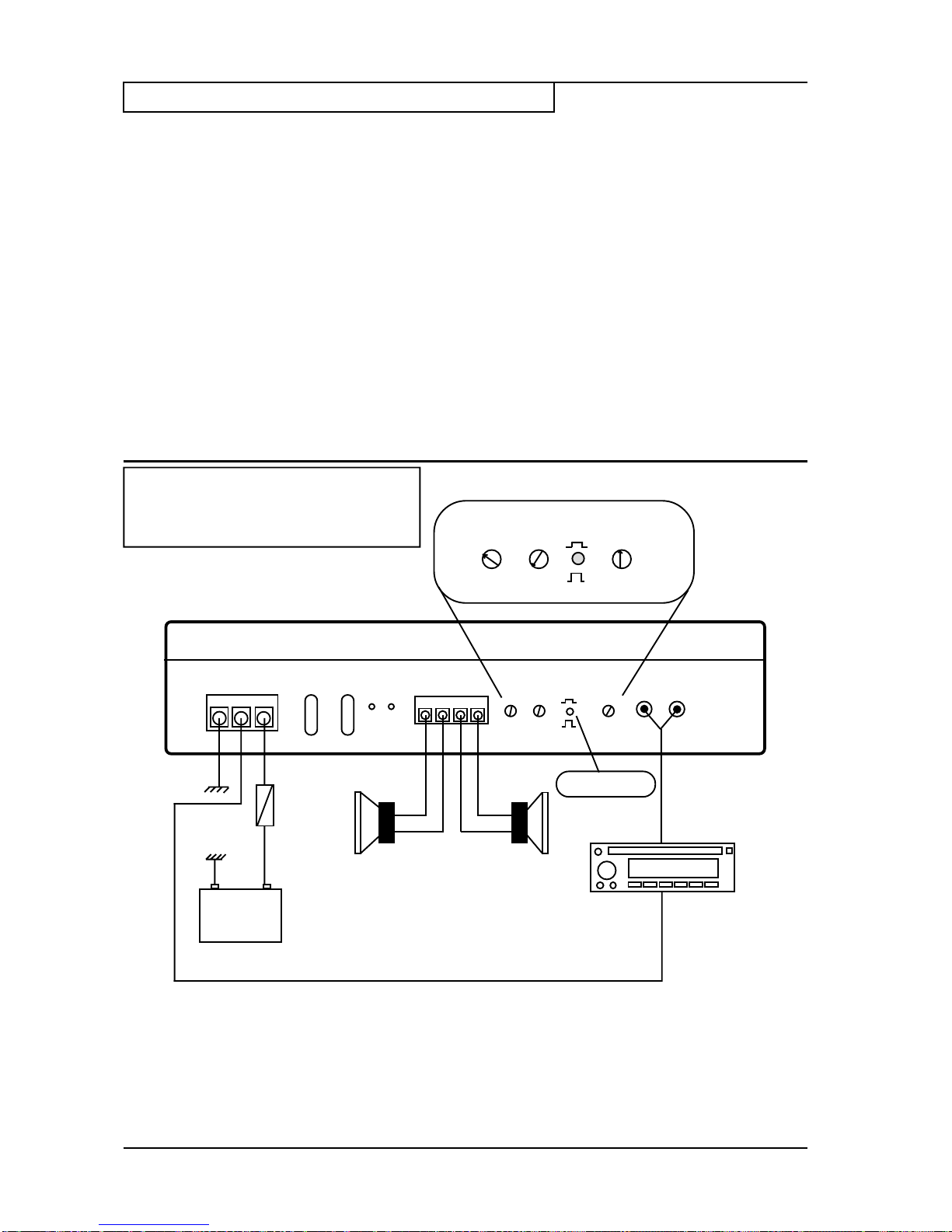
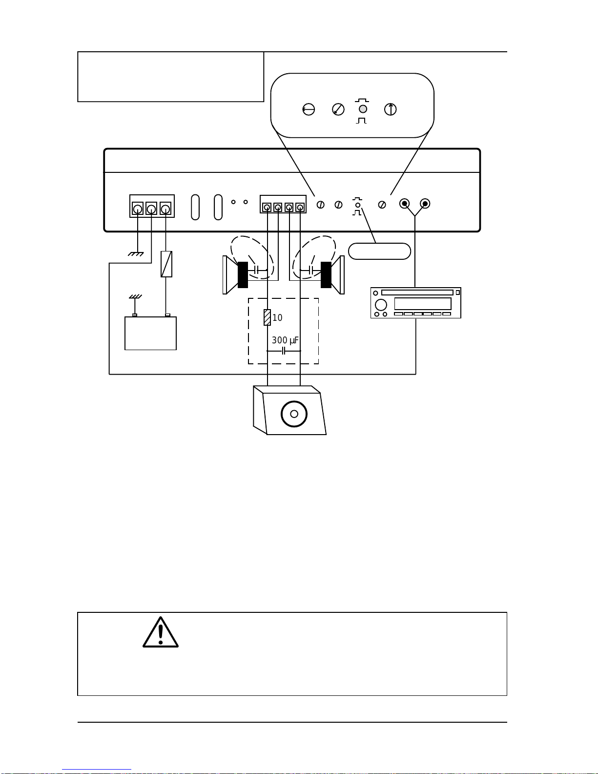
2.4 SPEAKER CONNECTION
The gold plated terminals will directly recieve
speaker cables up to 6 mm2(9AWG). Always
use high quality speaker cables such as DLS
SC 2x1,5, SC 2x2,5 or SC 2x4. Subwoofer
connection requires 2 x 4 mm2cable.
Connect the speaker + (marked with + or a red
dot) to the amplifier + terminal, and the speaker
- to the amplifier -.
When fitting the cables to the terminals, remove
only 10 mm of the insulation. Twist the wire
strand together and insert the wire after
loosening the terminal screw. Do not over tighten
as this can cut the cable strands. Use a 2 mm
hexagon key to the terminals.
If you want an extra high class speaker cable
choose any of the DLS SCP, SCK, SC 4x1 or
SC 4x1,5 cables.
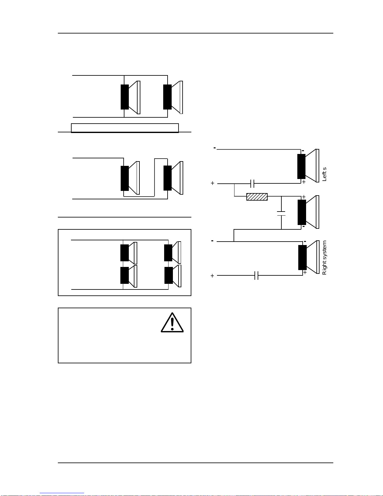
SPEAKER POLARITY CHECK.
All speakers in a car audio system should be
connected in phase (the same polarity).All speaker
conesmustmove in the samedirection.Outof phase
speakerswill cause alack of bass,and a poorstereo
soundstage.
Checking polarity:
Hold the - connection of the speaker wire to the -
terminalof a 1,5 Voltflashlight battery.Tapthe +wire
on to the + terminal of the battery, and observe the
movement of the cone. The cone should move
outwards when the wire touches the battery, and
inwardswhen the batteryis removed. If it isthe other
way around, the speaker has been connected
backwards and it must be removed and connected
correctly.
If your system also has a subwoofer connected
throughapassive6or12dBcrossover,trytoconnect
thiswithvariouspolarity and judge whatsoundsbest.
The phase shift in passive crossovers sometimes
makes it necessary to change polarity.
+
-
+
-
Battery
1,5
Volt
NOTE! Tweeters can not be tested this way, double
check the connections instead.
- 3 -
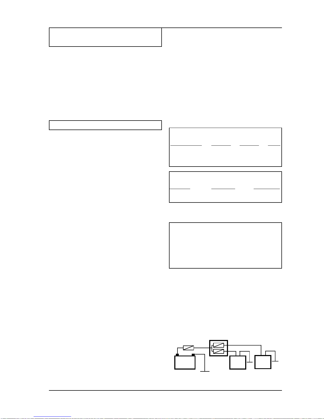
SPEAKER LOADS
Most car audio speakers have a 4 ohm impedance.
DLSamplifierscanbe loaded down to2ohmoneach
stereochannel.
Inmono bridge modeoperationthespeakerloadmust
neverbe lessthan 4ohm. Ifyou areusing morethan
one driver they must be connected in a way so the
impedance still is 4 ohm when connected to the
amplifier. When you run the amplifier in mono bridge
mode it sees a 4 ohm load as 2 ohm. On page 4 you
find different speaker wiring examples.
Don´t forget that the output power from a multimode
connected amplifier is more than double the normal
power. The speakers must be able to handle this
power.
PROTECT YOUR CABLES!
Topreventthecableinsulationfrom beeing damaged
over sharp metal edges we recommend the use of
cable protection tubes or similar. A damaged cable
insulationcould causeseriousdamagetotheamplifier
not covered by any guarantee.
CABLING, SIGNAL CABLES, SPEAKER CONNECTION