Important
Use either the low level or the high level input, do
not use both at same time.
Low level input
Usea pairofshielded stereoaudiocables withRCA
typejack.Thecable lengthvariesdependingon type
ofvehicle.Mostcablescanbe
bought in lengths from 1 up
to 5,5 meters.
Avoid placing the RCAcable
close to speaker cables,
power cables and remote
control cable. Connect to in-
put socket A & B.
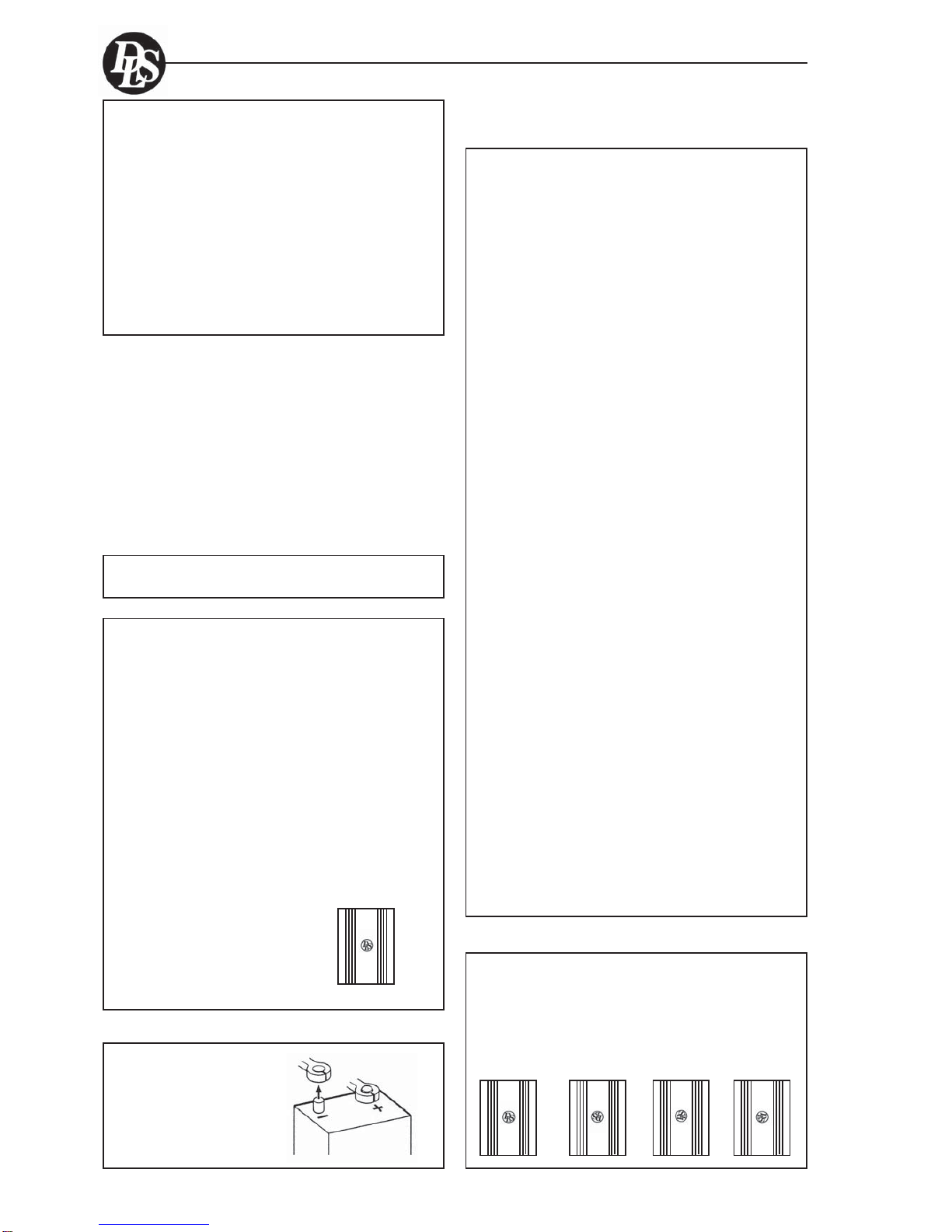
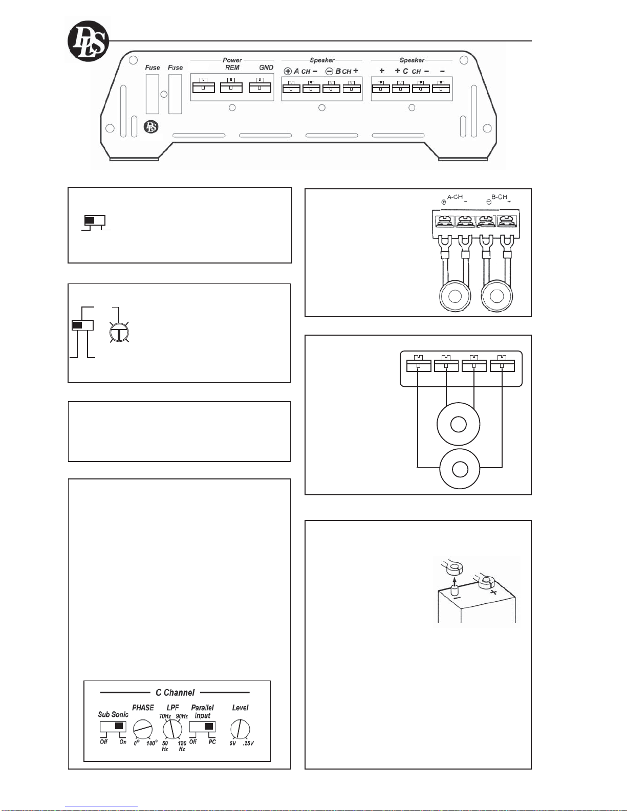
High Level Input
Connect left and right speaker wires coming from
the car stereo to the high level input as shown. You
mustconnect both plus andminusasthe inputs are
balanced,connectingplus onlygives lowerlevel and
bad sound quality. By changing the polarity of plus
and minus, you can change the phase.
Hihg level input socket.
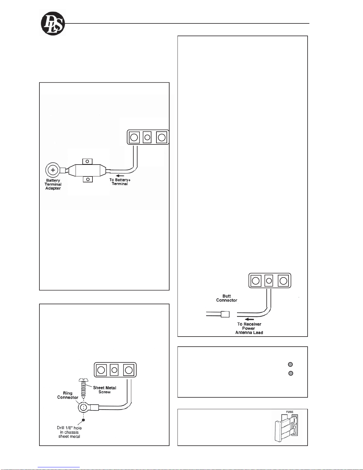
Automatic turn on when using high level input.
WiththeHi/Lowinput swichset toHi, theamplifier turns
onautomaticallyonhighinput.Youdon´tneedtoconnect
aseparateremotewirefromyourheadunit.
When using High Level input:
Set the switch to position ”Hi / Level”
When using Low level input:
Set the switch to position ”Low / Level”
If the switch is set to wrong
position, the amplifier still
works, but the risk for
disturbancesor distortion
increases.
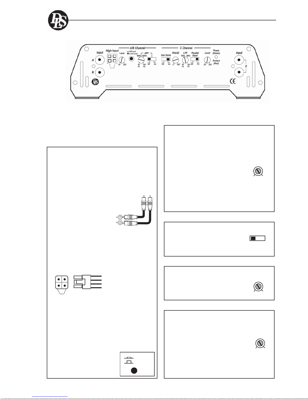
Input and controls
5
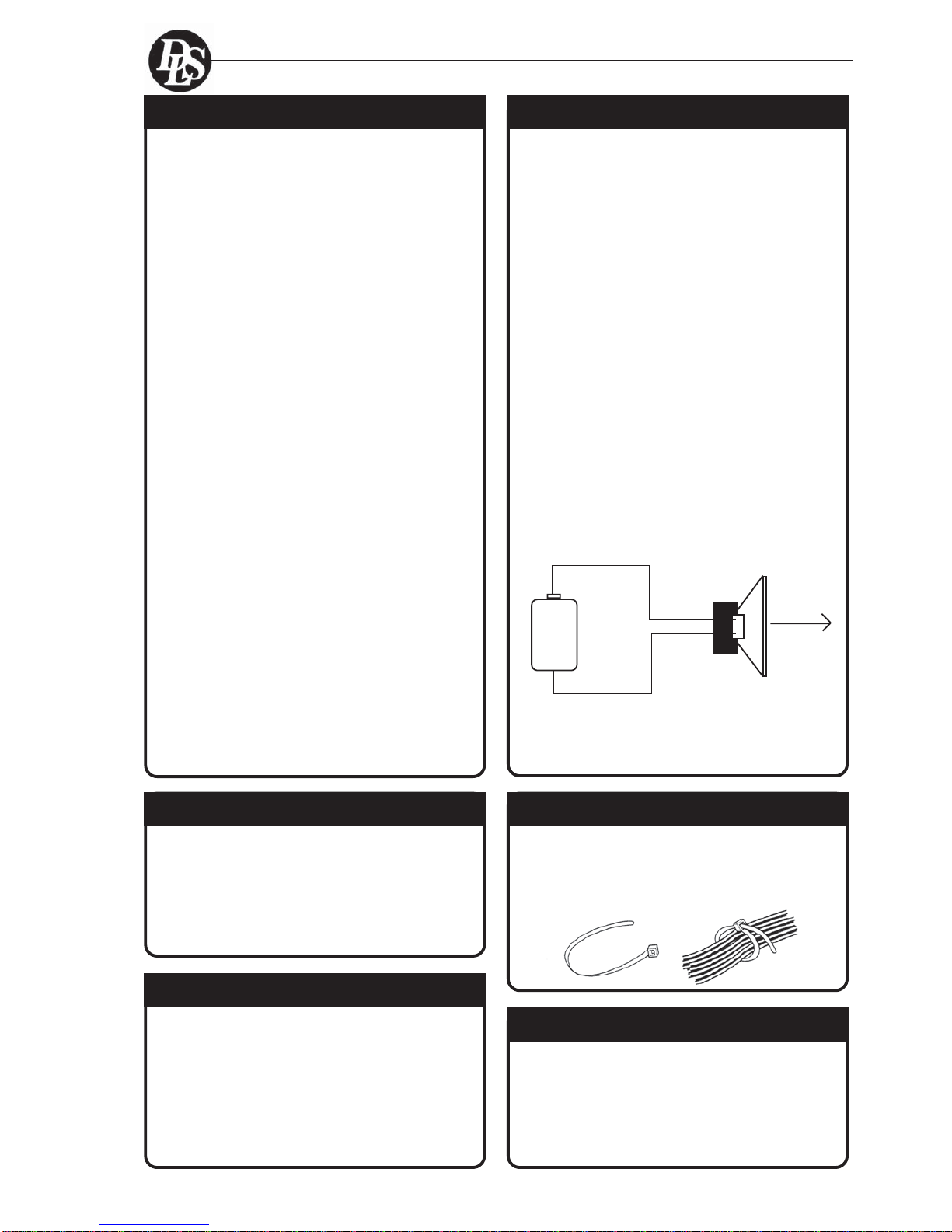
Input Level control ch. A/B/C (Level)
Subsonic filter ch. C
The Subsonic filter blocks the very
deepest frequenciesfromreachingthe
subwoofers. Thefilter crossover is 25
Hz and can be disconnected.
Low pass filter ch. C (LPF)
The LPF ( low pass filter ) allow low
frequencies only and blocks higher
frequencies.Atypicalsetting is 60 – 80
Hz.Choosethe settingthat soundsbest
in your car.
Phase control ch. C (PHASE)
The phase control can be set
continuously from 0 - 180 degrees. This
is very useful when you want to adjust
thebasssoundforbestfrontstageimage.
Start on 0 and turn the control slowly
clockwise until you experience the bass
sound coming from the front.
You may have to change the polarity of
the speaker connection to get the best
result.
HighInput White :A ch.+
White/black :A ch.-
Grey/black :B ch.-
Grey :B ch.+
Input Wiring
Inputsmaybe low level from the RCA output of the car
stereo or high level from the car stereo speaker
output.Low level = RCA is to prefer for the best sound
quality.
CAT31
Subsonic
Off On
LPF
50Hz 120Hz
The input level control, 5V – 0,25 V,
matches the output of your radio to the
input of the amplifier. After installation
is complete, make sure the input of the
amplifier is turned down all the way
(counter-clockwise at 5V ). Play a tape
or CD, make sure all bass or treble
settings or equalizer are flat, and turn
the volume of the radio up until you
just start to hear distortion. Turn the
volume control down just a bit. On the
amplifierincrease theinput levelcontrol
(clockwise or to the right ) until you just
start to hear distortion, then back the
level control just a bit. Now your radio
andamplifier levels are matched.
Level
5 V 0,25 V
Phase
0o180o
Hi / Level
Low / Level