manuals.online logo
Brands
  1. Home
  2. •
  3. Brands
  4. •
  5. DLS
  6. •
  7. Car Amplifier
  8. •
  9. DLS SOUND HANDBOOK User manual

DLS SOUND HANDBOOK User manual

This manual suits for next models

22

Other DLS Car Amplifier manuals

DLS RA10 Instruction sheet

DLS

DLS RA10 Instruction sheet

DLS CA22 Instruction sheet

DLS

DLS CA22 Instruction sheet

DLS SuperNaturalSound Reference 100 User manual

DLS

DLS SuperNaturalSound Reference 100 User manual

DLS CAT31 Instruction sheet

DLS

DLS CAT31 Instruction sheet

DLS CLASSICAMPENG03 Instruction sheet

DLS

DLS CLASSICAMPENG03 Instruction sheet

DLS Performance series User manual

DLS

DLS Performance series User manual

DLS CAD1000 Instruction sheet

DLS

DLS CAD1000 Instruction sheet

DLS AMPREFEN User manual

DLS

DLS AMPREFEN User manual

DLS RA20 Instruction sheet

DLS

DLS RA20 Instruction sheet

DLS RA25 Instruction sheet

DLS

DLS RA25 Instruction sheet

DLS BRXAMPEN User manual

DLS

DLS BRXAMPEN User manual

DLS CA30ENG Instruction sheet

DLS

DLS CA30ENG Instruction sheet

DLS X-program X-D10 User manual

DLS

DLS X-program X-D10 User manual

DLS AMPD1000E User manual

DLS

DLS AMPD1000E User manual

Popular Car Amplifier manuals by other brands

Boss Audio Systems US140 user manual

Boss Audio Systems

Boss Audio Systems US140 user manual

Boss Audio Systems FNX2000 user manual

Boss Audio Systems

Boss Audio Systems FNX2000 user manual

Pioneer GM-D8500M owner's manual

Pioneer

Pioneer GM-D8500M owner's manual

MTX Thunder Marine TM904 user guide

MTX

MTX Thunder Marine TM904 user guide

MTX Thunder TA Super TA92001 Connection guide

MTX

MTX Thunder TA Super TA92001 Connection guide

Lanier 480-0239 Material safety data sheet

Lanier

Lanier 480-0239 Material safety data sheet

Kenwood KAC-642 instruction manual

Kenwood

Kenwood KAC-642 instruction manual

Sony XM-405EQX Marketing Specifications Product guide

Sony

Sony XM-405EQX Marketing Specifications Product guide

Jensen XA4150 owner's manual

Jensen

Jensen XA4150 owner's manual

Audiopipe AQX-660.2 owner's manual

Audiopipe

Audiopipe AQX-660.2 owner's manual

Clarion APA2001  APA2001 APA2001 Owners & installation manual

Clarion

Clarion APA2001 APA2001 APA2001 Owners & installation manual

Cyfre CHACDMA-819 installation manual

Cyfre

Cyfre CHACDMA-819 installation manual

Sony XM-7547 Service manual

Sony

Sony XM-7547 Service manual

Alpine PDX11000 - Amplifier Review guide

Alpine

Alpine PDX11000 - Amplifier Review guide

Steg Qx Mos 105.4x user manual

Steg

Steg Qx Mos 105.4x user manual

Jensen PS1220M Installation & operation manual

Jensen

Jensen PS1220M Installation & operation manual

Kenwood KAC-8105D instruction manual

Kenwood

Kenwood KAC-8105D instruction manual

Pioneer GM-5000T owner's manual

Pioneer

Pioneer GM-5000T owner's manual

manuals.online logo
manuals.online logoBrands
  • About & Mission
  • Contact us
  • Privacy Policy
  • Terms and Conditions

Copyright 2025 Manuals.Online. All Rights Reserved.

Hints and advices for car sound builders using
DLS amplifiers and speakers
DLS Svenska AB
P.O. Box 13029, SE-402 51 Göteborg, Sweden
Tel. +46 31 84 00 60
Fax +46 31 84 40 21
E-mail: [email protected]
www.dls.se
CONTENTS:
Page
1 Introduction
2 - 3 Formulas and facts
4 - 5 Amplifier facts
6 - 8 Passive crossover filters
9 Cabling
10 - 13 Installation
14 - 20 Building speaker boxes
21 Enclosure examples
22 Some useful tables
SOUND HANDBOOK
INTRODUCTION
We have made this handbook as a small help for
thoose who want to do a first class car sound instal-
lation.
This book advices the reader in matters concerning
amplifier and speaker installation and wiring, passive
crossovers, cable choice and different bass box
constructions. Information about DLS products can
also be found on our Internet WEB-site www.dls.se
DLS SOUND PHILOSOPHY
DLS sound philosophy is based upon providing
equipment that will accurately and faithfully reproduce
all kinds of music without distortion and colouration.
The sound reproduction must be natural, the
soundstage well imaged and stable even when the
tweeters are mounted apart from the bass/midrange
elements.
If you close your eyes the sound should be as close
as possible to the real. You should be able to
experience the sound as it is in the concert hall or on
a rock concert. Every instrument and singer should
be on it´s correct place on the stage. To achieve this
you need a good front stage image and to do such
an installation is not easy. DLS amplifiers and spea-
ker systems will help you to achive a sound as good
as possible, but you also have to do a correct instal-
lation if you want a perfect result. This book will give
you hints about doing a good installation.
1
Depending upon the construction, amplifiers are
divided into different classes, there are class A, AB,
B or C. The characteristic mark for a class A amplifier
is the lack of switching noise distortion, which the
other types have. The class A amplifier also has a
higher idle current, but instead it creates a much bet-
ter resoulution and dynamics. For home use the class
A amplifiers are not very common, many people think
they are only for sound connoisseurs and Hi-Fi
entusiasts.Powers from 2x15 up to 2x50 Watts are
common on these types, no high power, but instead
real good AC/DC-converters with reliable power
resources.
The most common amplifier type is class AB.
Now you can also find class "D" amplifiers. Class D
amplifiers process the signal in a digital way and this
gives the amplifier a high efficiency. A normal class
AB amplifier has an efficiency of around 50%. This
means that a 500 watt amplifier will take up to a 1000
watts from the battery and 50% of it will be transfor-
med to heat. The power transistors must work very
hard and will get very hot. A class D amplifier has an
efficiency of 80-90%. and the heat dissipation is much
lower. The power consumption is also much lower.
The disadvantage of a class D amplifier is the higher
distorsion and it is also difficult to make it work over
the entire audiable frequency range. Class D
amplifiers are normally used only as subwoofer
amplifiers with limited frequency range.
AMPLIFIER CLASSES
DLS lay a great job in developing and refining the
different products in order to give the market the best
Car-Hi-Fi products possible to the worlds most
demanding listeners.
A wellknown french sound philosopher, Jean Hiraga,
said regarding home Hi-Fi: A good sound starts in
the mains plug and then through the AC/DC-
converter, which must be oversized.
The same is valid for Car Hi-Fi, the amplifier must at
all occasions have enough power to make a good
job. Remember to use well oversized cables from
the battery to the amplifier. It is also essential that
the DC/DC-converter is well oversized to make it
distribute enough power to the amplifiers final stage
when it´s needed, otherwise both the dynamics and
the good sound will be lost. The amplifier will sound
"tired" and the sound will be strained. The bass will
lack the real "bass-kick" and the treble becomes sharp
instead of soft and airy.
The built-in amplifers in most CD:s and stereo casette
players can´t stand up to these demands. To achieve
a good sound it´s necessary to install an external
high quality amplifier.
DLS AMPLIFIER PHILOSOPHY
DLS SOUND HANDBOOK - INTRODUCTION
DLS AMPLIFIERS 2007:
DLS amplifiers in ULTIMATE series work in class
AB. In order to minimize the transient distorsion the
final stage uses accurately matched transistor
These are the ULTIMATE-series models:
A2 - The Mid Stereo
A3 - The Twin Mono
A4 - The Big Four
A5 - The Big Five
A6 - The Mono Amp
A7 - The Big Five
TA2 - Tube amplifier
The Reference amplifiers are also working in class
AB.
These are the Reference-series models:
RA10, RA20, RA25, RA30, RA40 & RA50.
These are the Performance-series models:
CA12, CA22, CA23, CA31, CA41, CA51, CAD11 &
CAD15.
CAT31-24 is a CA31 for 24 Volt use.
FORMULAS
It's easier to understand some parts in this book if
you know some of the formulas on this page. They
are also useful at many other occasions.
Box volumes (V):
When caculating the volume of a box you simply
multiply the width (W) x heigth (H) x depth (D).
Use measures in dm and you will get the answer in
liters.
A trapezoid box is calulated as below:
Volume =
width (W) x heigth (H) x ((upper depth + lower depth)/2)
W
H
UD
LD
OHMS LAW:
R = resistance in ohm, U = voltage in Volt
I = current in Ampere, P = power in Watt
Volume (V) of a pipe:
D = depth (length) r = radius
V = r2x 3,14 x D
2
r
MEASURE CONVERSION
The following relation between some units are
useful to know of.
1 yard (yd) = 3 ft = 36 in = 0,9144 m
1 foot (ft) = 0,3048 m
1 inch (in) = 2,54 cm
1 square yard (yd2) = 9 ft2 = 1296 in2 = 0,8361 m2
1 square foot (ft2) = 144 in2= 9,290 dm2
1 square inch (in2) = 6,452 cm2
1 cubic yard (yd3) = 27 ft3= 0,7646 m3
1 cubic foot (ft3) = 1728 in3= 28,32 dm3
1 cubic inch (in3) = 16,39 cm3
1 pound (lb) = 16 oz = 0,4536 kg
1 ounce (oz) = 28,35 gram
CONVERSION GAUGE - mm2
Gauge (ga) is an American measure for cable
areas, also called AWG (American Wire Gauge).
1 AWG = 42 mm29 AWG = 6,8 mm2
2 AWG = 33 mm210 AWG = 5,3 mm2
3 AWG = 27 mm211 AWG = 4,2 mm2
4 AWG = 21 mm212 AWG = 3 mm2
5 AWG = 16 mm213 AWG = 2,7 mm2
6 AWG = 13 mm214 AWG = 2 mm2
7 AWG = 10 mm215 AWG = 1,65 mm2
8 AWG = 8 mm216 AWG = 1,3 mm2
SPEAKER TERMS
It´s useful to know what the most common speaker
data terms stands for.
Fs = speaker resonant frequency in Hz
Fc = box resonant frequency in Hz
F3 = approximative lower frequency for vented
boxes in Hz. Often called F-3 dB point = the point
where the power is half.
Qes = the speakers electrical Q-value
Qms = the speakers mechanical Q-value
Qts = the speakers total Q-value
Vas = Eqvivalent air volume. The air volume having
the same aqoustic compliance as the speaker
suspension.
X-max = voice coil length - 2 x thickness of the
inner pole plate.
Sd = the speakers effective cone area
Vb = net volyme of the box
SPL = sound pressure level in dB
Sens. = speaker sensitivity in dB at 1Watt / 1 mtr
Re = speaker DC resistance in ohms
Mms (Mmd) = moving mass
Le (Lbm) = Voice coil inductance
RMS = AC average power value
BL = The flux density factor in the magnetic gap in
the speaker * the wire length of the voice coil
GEOMETHRY:
Circel:
r = radius O = periphery
d= diameter A = area
Radius (r) = O Diameter (d) = O
2π π
Periphery (O) = 2π x r Area (A) = πx r2
To get the net volume use the inner measures of
the box.
Use measures in dm
and you will get the
answer in liters.
DLS SOUND HANDBOOK - FORMULAS AND FACTS
DECIBEL - dB
Examples of fixed dB relations:
For voltage and current:
dB Amplification
0 dB 1 time
1 dB 1,1 times
3 db 1,4 times
6 dB 2 times (double)
10 dB 3,16 times
20 dB 10 times
The amplification increases logarithmic.
For power:
dB Amplification
0 dB 1 time
3 dB 2 times
6 dB 4 times
10 dB 10 times
20 dB 100 times
An attentuation of -6 dB is a half for voltage and
current and a quarter when talking about power.
CONNECTING RESISTORS
4 Ω6 Ω
8 Ω12 Ω
R tot = 4 + 6 + 8 + 12 = 30 Ω
IN PARALLEL:
When connecting in parallel the total resistance
always becomes lower, it is always lower than the
lowest resistor value in the connection.
Formula:1 = 1 + 1 + 1 + 1
R R1 R2 R3 R4
1 = 1 + 1 + 1 + 1
R4 4 8 8
CONNECTION OF CAPACITORS
4 Ω8 Ω
8 Ω
4 Ω
R = 1,33 Ω
Capacitors acts in the opposite way as resistors when
connected in series or parallel.
IN PARALLEL:
The total capacitance when connecting capacitors in
parallel is the sum of each capacitor.
C tot = C1 + C2 + C3 + C4 etc.
10 μF50 μF50 μF100 μF
C tot = 10 + 50 + 50 + 100 = 210 μF
When connecting only two resistors in parallel you
can use the formula below.
R1 x R2 4 x 8
R1 + R2 4 + 8
R = Ex. 32
12
== 2,66Ω
Formula: 1 = 1 + 1 + 1 + 1
C C1 C2 C3 C4
100 μF50 μF
50 μF
10 μF
1 = 1 + 1 + 1 + 1
C 10 50 50 100 C= 6,66 μF
1 μF = 0,000001 Farad (10-6)
1 nF = 0,000000001 Farad (10-9)
1 pF = 0,000000000001 Farad (10-12)
dB is a unit used to describe a realation. It´s used to
describe an amplification as well as an attentuation.
At an attentuation a minus sign is put before the figure.
An amplification is the relation between the input and
the output signal. In can be valid for voltage, current
or power.
When used for power amplification you must
remember that current x voltage = power. This means
that the relation becomes larger, see the table below.
The formualas below is valid when connecting
resistors and inductances in series or in parallel.
It can also be used for speakers.
IN SERIES:
The total resistance is equal to the sum of all
resistors in the connection.
R tot = R1 + R2 + R3 + R4 etc.
When connecting only two capacitors you can use
the same formula as in the example with two
resistors connected in parallel above.
3
IN SERIES:
When connecting capacitors in series you calculate
in the same way as for resistors connected in parallel.
DLS SOUND HANDBOOK - FORMULAS AND FACTS
4
DLS SOUND HANDBOOK - AMPLIFIER FACTS
DLS REFERENCE RA20 RA25 RA30 RA40 RA50
FILTER CONFIGURATION RA50
Ch. 1 & 2
High-pass 50 - 140 Hz*
Low-pass 250 - 700 Hz* (x 1 switch)
or 2,5 kHz - 7 kHz* (x 10 switch)
Ch. 3 & 4
High-pass 50 Hz - 140 Hz (x 1 switch)
or 250 Hz - 700 Hz (x 5 switch)
or 2,5 kHz - 7 kHz (x 50 switch)
Ch. 5
Low-pass 40 Hz - 125 Hz
Subsonic fixed 25 Hz*
*can be switched in/out
Number of channels 2 2 2 4 3 1 5 4
Power output in 4 ohm 2x45 W 2x85 W 2x150 W 4x85 W 2x85 W 1x500 W 4x60 W 4x40W
Power output in 2 ohm 2x80 W 2x145 W 2x270 W 4x145 W 2x100 W 1x870 W 4x100W 4x80 W
Power output in 1 ohm 2x120 W 2x220 W 2x425 W 2x220 W - 1x1200 W - -
Mono bridge mode 4 ohm 1x160 W 1x290 W 1x550 W 2x250 W - - - 2x165W
Mono bridge mode 2 ohm 1x240 W 1x450 W 1x870 W 2x400 W 2x220W
Mono bridge mode 1 ohm - - 1x1200 W -
Mono sub channel, nom. power 4 ohm
- - - - 1x300 W - 1x300 W -
Mono sub channel, nom. power 2 ohm
- - - - 1x500 W - 1x440 W -
Mono sub channel, nom. power 1 ohm 1x780 W 1x600 W
S / N ratio, A-weighted >100 dB >100 dB >100 dB >100 dB >100 dB >100 dB >100 dB >100 dB
Damping factor >200 >200 >200 >200 >200 >200 >200 >200
Input impedance >10 k >10 k >10 k >10 k >10 k >10 k >10 k >10 k
Input sensitivity 0,2-7V 0,2-7V 0,2-7V 0,2-7V 0,2-7V 0,2-7V 0,3-7V 0,5-5V
Filter highpass 20-200 Hz 20-200 Hz 20-200 Hz FRONT: LP: 50-125 Hz 50-150 Hz - FRONT: 80-400Hz / 1,6-8 kHz OFF/70/90 Hz
HP: 20-200 / 60-600 Hz REAR: 80-400 Hz
Filter lowpass OFF/70/90 Hz 50-125 Hz* 50-125 Hz* REAR:
LP: 45-200 / 90-400 Hz
40-90 Hz 50-125 Hz REAR: 0,3-4 kHz / 3-40 kHz 50-125 Hz
HP: 20-200 Hz SUB CH: 50-125 Hz
*can be switched in/out SUBSONIC: 25 Hz
Subsonic filter 25 Hz/18 dB - - - - yes yes no -
Dual DC-inputs - - yes yes - yes - -
Phase shift button 0 / 180° - - yes - - - - -
Phase shift control continuous - - - - 0-180 degrees 0-180 degrees 0-180 degrees -
Fan output terminal - - yes yes yes yes yes -
Remote sub level control - - - - yes yes yes -
POWER CONSUMPTION
Idle 0,5 A 0,6 A 1,1 A 1,5 A 0,5 A 0,6 A 1,1 A 0,7 A
Maximum 32 A 60 A 140 A 95 A 90 A 140 A 120 A 50 A
Dimensions (mm) 205x240x73 265x240x73 410x240x73 465x940x73 410x240x73 410x240x73 605x240x73 350x240x73
Dimensions (inch) 8,07x9,45x2,87 10,43x9,45x2,87 16,15x9,45x2,87 18,30x9,45x2,87 16,15x9,45x2,87 16,15x9,45x2,87 23,82x9,45x2,87 13,78x9,45x2,87
Weight 2,8 kg (6,17 lb) 3,7 kg (8,16 lb) 6,2 kg (13,67 lb) 6,6 kg (14,55 lb) 5,9 kg (13 lb) 6,2 kg (13,67 lb) 8,1 kg (17,86 lb) 4,8 kg (10,6 lb)
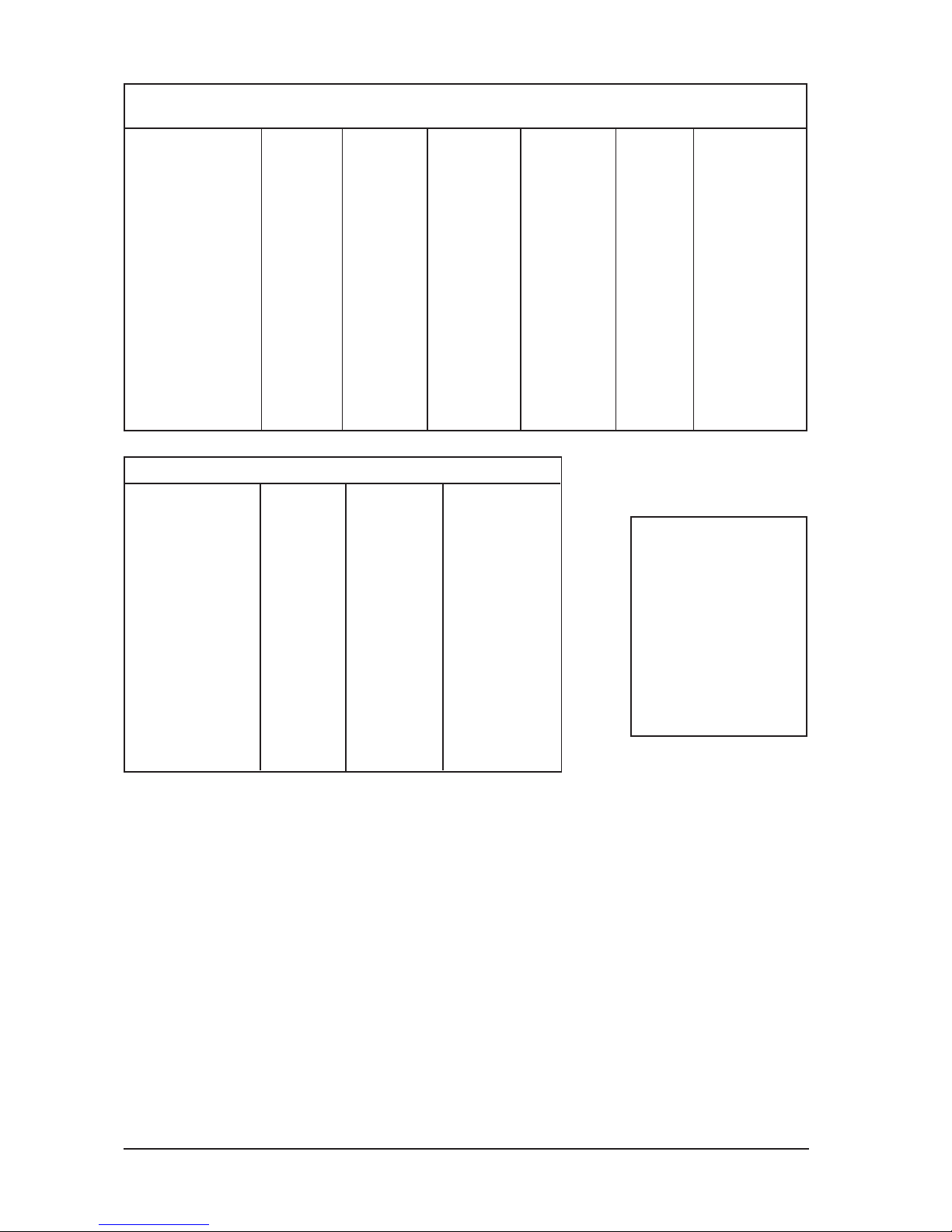
DLS ULTIMATE AMPLIFIERS A1 A2 A3 A4 A5 A6 A7 A8
Number of channels 2 2 3 4 5
Power output in 4 ohm 2 x 130 W 2 x 70 W 2 x 70 W + 1 x 265 W 4 x 75 W 4 x 70 W + 1 x 265 W
Power output in 2 ohm 2 x 220 W 2 x 110 W 2 x 100 W + 1 x 365 W 4 x 110 W 4 x 110 W + 1 x 365 W
Power output 4 ohm bridged 1 x 440 W 1 x 220 W - 2 x 220 W 2 x 220 W
Signal to noise ratio, A-weighted >100 dB >100 dB >100 dB >100 dB >100 dB
Damping factor >200 >200 >200 >200 >200
Frequency response +/- 0,5 dB 10 Hz - 50 kHz 10 Hz - 50 kHz 10 Hz - 50 kHz 10 Hz - 50 kHz 10 Hz - 50 kHz
Input impedance, low level >10 kohms >10 kohms >10 kohms >10 kohms >10 kohm
Input impedance, high level 330 ohms 330 ohms 330 ohms 330 ohms 330 ohm
High level input with auto start yes yes yes yes yes
Input sensitivity 0,2 - 7 V 0,2 - 7 V 0,2 - 7 V 0,2 - 7 V 0,5 - 8 V
Bass boost adjustable gain @ 40 Hz 0 - +18 dB - 0 - +18 dB 0 - +18 dB 0 - +18 dB
Phase shift 0 - 180 degrees continuously yes - yes yes yes
Remote bass level and phase shift - - yes, on sub ch. - yes, on sub ch.
Filter highpass / fixed subsonic filter 20 - 150 Hz* 20 - 150 Hz* 45 - 125 Hz* / 25 Hz* 20 - 150 Hz on all ch. see spec.
Filter lowpass 40 - 125 Hz* - 40 - 125 Hz 40 - 125 Hz* see spec.
*can be switched in/out
POWER CONSUMPTION
Idle 0,6 A 0,6 A 0,9 A 0,9 A 1,2A
Maximum 50 A 25A 70 A 50 A 90 A
Fuses 2 x 25 A 1 x 25 A 2 x 35 A 2 x 25 A 3 x 30A
Dimensions (mm) 59 x 359 x 245 59 x 247 x 245 59 x 385 x 245 59 x 359 x 245 59 x 479 x 245 mm
Dimensions (inch) 2,33 x 14,1 x 9,65 2,33 x 9,72 x 9,65 2,33 x 15,15 x 9,65 2,33 x 14,1 x 9,65 2,33 x 18,85 x 9,65
Weight 3,8 kg / 8,4 lb 2,6 kg / 5,7 lb 4,4 kg /9,3 lb 4 kg / 8,8 lb 5,5 kg / 12,1 lb
R.M.S. Power output at 13,8 Volts, 20 Hz - 20 kHz, max 0,1% THD, all channels driven:
Number of channels 1
Amplifier class AB
Power output in 4 ohm (0,1% THD) 1 x 300 W
Power output in 2 ohm (0,1% THD) 1 x 500 W
Power output in 1 ohm (0,1% THD) 1 x 820 W
All power ratings at 13,8 Volt
Signal to noise ratio, A-weighted >100 dB
Damping factor >200
Frequency response 10 Hz - 125 Hz
Input impedance >10 kohms
Input impedance, high level 330 ohms
High level input with auto start Yes
Input sensitivity 0,5 - 8 V
Phase control continuous 0 - 180 degrees
Bass boost adjustable gain 0 - +18 dB
Filter subsonic, 18 dB slope 25 Hz fixed
Filter lowpass 12 dB slope 40 - 125 Hz
*can be switched in/out
Power consumption, idle 1,5 A
Fuse 3 x 40 A
Dimensions (mm) 59 x 359 x 245
Dimensions (inch) 2,33 x 14,1 x 9,65
Weight 5,4 kg / 11,9 lb
DLS REFERENCE RA10
5
FILTER CONFIGURATION CA 41& CA 51
Ch. A & B
High-pass 15 - 500 Hz*
Low-pass 50(500) - 500(5k) Hz*
(x 10 switch)
Ch. C & D
High-pass 15(150) Hz - 500(5k) Hz*
(x 10 switch)
Ch. E (only CA51)
Low-pass 60 Hz - 120 Hz
Subsonic 25 Hz*
*can be switched in/out
DLS SOUND HANDBOOK - AMPLIFIER FACTS
Number of channels 1 1 1
Amplifier class D (digital) D (digital) AB
Power output in 4 ohm (0,2% THD) 1 x 400 W 1 x 550 W 1 x 220 W
Power output in 2 ohm (0,2% THD) 1 x 750 W 1 x 900 W 1 x 400 W
Power output in 1 ohm (0,5% THD) 1 x 1050 W 1 x 1600 W 1 x 500 W
All power ratings at 13,8 Volt
Signal to noise ratio, A-weighted >100 dB >100 dB >100 dB
Damping factor >100 >100 >100
Frequency response 15 Hz - 160 Hz 15 Hz - 160 Hz 10 Hz - 35 kHz
Input impedance 10 kohms 10 kohms 10 kohms
Input impedance, high level 100 ohms 100 ohms 100 ohms
High level input with auto start Yes Yes Yes
Input sensitivity 0,15 - 5 V 0,15 - 5 V 0,25 - 5 V
Phase control continuous 0 - 180 degrees 0 - 180 degrees 0 - 180 degrees
Remote bass level control yes Yes No
Bass boost adjustable gain @ 45 Hz 0 - +18 dB 0 - +18 dB -
Filter subsonic, 24 dB slope 15-50 Hz variable 15-50 Hz variable 15 - 150 Hz variable
Filter lowpass 24 dB slope 15 - 150 Hz variable 15 - 150 Hz variable 50 - 500 Hz variable
Bridge mode master/slave selector Yes Yes No
Built-in fan cooling Yes Yes Yes
Power consumption, idle / max 1,5 A / 120 A 2 A / 160 A 0,8 A / 60 A
Fuse 4 x 30 A 4 x 40 A 2 x 30 A
Dimensions (mm) 70 x 444 x 268 70 x 473 x 268 70 x 312 x 268
Dimensions (inch) 2,92 x 17,48 x 10,55 2,92 x 18,6 x 10,55 2,92 x 12,28 x 10,55
Weight 5,8 kg / 12,79 lb 6,4 kg / 14,33 lb 3,8 kg / 8,4 lb
DLS Performance CAD 11 CAD15 CA12
Number of channels 2 2 3 3 4 5
Power output in 4 ohm (0,1% THD) 2 x 60 W 2 x 135 W 2 x 65 W + 1 x 170 W 2 x 75 W + 1 x 170 W 4 x 70 W 4 x 50 W + 1 x 170 W
Power output in 2 ohm (0,2% THD) 2 x 100 W 2 x 200 W 2 x 90 W + 1 x 280 W 2 x 145 W + 1 x 280 W 4 x 125 W 4 x 80 W + 1 x 225 W
Power output in 1 ohm (0,5% THD) 2 x 210 W + N/A
Power output 4 ohm bridged 1 x 200 W 1 x 400 W 1 x 170 W 1 x 280 W 2 x 200 W 2 x 150 W
Signal to noise ratio, A-weighted >100 dB >100 dB >100 dB >90 dB >100 dB >100dB
Damping factor >100 >100 >100 >100 >100 >100
Frequency response 10 Hz - 35 kHz 10 Hz - 35 kHz 10 Hz - 35 kHz 10 Hz - 35 kHz 10 Hz - 35 kHz
Input impedance, low level >10 kohms >10 kohms >10 kohms 10 Hz - 35 kHz >10 kohms >10 kohms
Input impedance, high level 100 ohms 100 ohms 100 ohms 100 ohms 100 ohms 100 ohms
High level input with auto start yes yes yes yes yes yes
Low output yes yes no no yes No
Input sensitivity 0,25 - 5 V 0,25 - 5 V 0,25 - 5 V 0,25 - 5 V 0,25 - 5 V 0,25 - 5 V
Gramd bass adjustable frequency - 25 Hz - 80 Hz no no 25 Hz - 80 Hz no
Grand bass adjustable gain - 0 - 18 dB no no 0 - 18 dB no
Phase control continous no no 0-180 degrees 0-180 degrees no 0-180 degrees
Filter highpass / subsonic 15 - 500 Hz* 15 - 150 Hz* 15 - 150 Hz* / Yes, 25 Hz* 50 - 150 Hz* / Yes, 25 Hz* see spec. see spec.
Filter lowpass 50 - 500 Hz* 50 - 500 Hz* 50 - 120 Hz 50- 120 Hz, 24 dB slope see spec. see spec.
*can be switched in/out NOTE! For 24 volt use
POWER CONSUMPTION
Idle / max 0,5 A / 25 A 0,7 A / 60 A 1,0 A / 60 A 0,7 A / 40 A 0,7 A / 60 A 1,0 / 90 A
fuses 1 x 25 A 2 x 30 A 2 x 30 A 2 x 20 A 2 x 30 A 3 x 30 A
Dimensions (mm) 70 x 230 x 268 70 x 312 x 268 70 x 357 x 268 70 x 357 x 268 70 x 372 x 268 70 x 437 x 268
Dimensions (inch) 2,92 x 9,06 x 10,55 2,92 x 12,28 x 10,55 2,92 x 14,06 x 10,55 2,92 x 14,06 x 10,55 2,92 x 14,65 x 10,55 2,92 x 17,2 x 10,55
Weight 2,7 kg / 6,2 lb 3,6 kg / 7,9 lb 4 kg /9,2 lb 4 kg / 9,2 lb 4,2 kg / 9,3 lb 5 kg / 11 lb
DLS Performance CA 22 CA 23 CA 31 CAT 31 CA 41 CA 51
R.M.S. Power output at 13,8 Volts, 20 Hz - 20 kHz, all channels driven:
CROSSOVERS
The ideal speaker, able to reproduce all frequencies
from lowest bass to highest treble, is not yet invented.
Instead we have to use two or more speakers where
each speaker is reproducing a part of the frequency
range.
To make this work the input signal to each speaker
driver must contain only the frequencies it´s desig-
ned for. For this purpose we need crossover filters.
ACTIVE CROSSOVERS
Crossovers can be ACTIVE or PASSIVE. An active
filter is connected before the amplifier line input. You
need one amplifier for each speaker pair which will
become rather expensive.
But the advantages are that it´s possible to mix
speakers with different impedance or sensitivity and
still be able to balance the system.
Most amplifiers are equipped with built-in active
crossovers that can be adjusted in frequency and also
switched in-out.
All DLS amplifiers have built-in active crossovers.
PASSIVE CROSSOVERS
Passive crossover consists of coils and capacitors,
and sometimes resistors for impedance adaption. A
passive filter is connected between the amplifier and
the speaker and is of LC-type, (coil and capacitor).
A coil stops the higher frequencies while the low pas-
ses through, a capacitor works in the opposite way.
By changing the component values, different cross-
over frequencies are obtained. The coils must be of
high quality with a large wire area to avoid losses
and distortion. Air coils without iron core are the best
but they can be rather big for high values. For high
values we often use coils with an iron core. The best
capacitors are of polyester type. For large
capacitance values bipolar electrolytic capacitors are
used.
Resistors are used in a filter for impedance adap-
tion. Read the part about conjugate compensation.
A passive filter steals more power than an active.
CROSSOVER EXAMPLES:
(without conjugate compensation)
3-WAY SYSTEM:
4-WAY SYSTEM:
123
1
2
3
1
2
3
123
12
12
12
12
12
12
12
Sub-bass Mid-range Tweeter
0-80 Hz80 Hz - 5 kHz 5 kHz -
10 mH
10 mH
300 μF
300 μF5,6 μF
0,18
mH
+
-
12 dB filter slope
+
-
12 dB filter slope
123
1
2
3
1
2
3
123
12
12
12
12
12
12
12
12
12
12
12
12
12
12
12
12
The systems above are shown without impedance
compensation. Read below about conjugate links.
10 mH
10 mH
300 μF
1,75 mH
1,75 mH
0,18 mH
50 μF
300 μF
Sub-bass Mid-bass Mid-range Tweeter
0-80 Hz80 - 520 Hz 520 - 5 kHz 5 kHz -
50 μF
5,6 μF
PHASE SHIFT IN PASSIVE CROSSOVERS
All passive crossovers will phase shift the signal.
A 6 dB filter shifts 90 degrees and a 12 dB 180
degrees. Because of this you should always try to
phase reverse the tweeter in a system to see what
phase is creating the best sound. In a 3-way system
it´s normal to phase reverse the tweeter. All tweeters
used in a system must have the same polarity
(phase). Also subwoofers with a 12 dB crossover
should you try to phase reverse. If the subwoofer cone
is moving but you don´t achieve any good bass you
can try to phase reverse. If two subwoofers are
connected with different polarity (phase), the sound
from each speaker will kill the sound from the other,
resulting in a poor bass reproduction.
CONJUGATE COMPENSATION:
Conjugate compensation is a way to equal the spea-
ker load over the whole frequency range. A 4 ohm
speaker can have an impedance peak up to 25 times
the normal at the resonant frequency (Fs). To make
the calculated crossover filter to match, you can
connect a conjugate link in parallel with the speaker.
It´s normally made of a capacitor and a resistor. If
you cant calculate the exact component values for
the conjugate link you can use a 33 μF capacitor in
series with a 3,9 ohm resistor to most 4", 5,25" and
6,5" speakers.
DLS SOUND HANDBOOK - PASSIVE X-OVER FILTERS
CROSSOVER FREQUENCIES:
In a two-way system with separate tweeter a cross-
over frequency from 3 - 8 kHz is normal.
In a three-way system it´s normal to split the sub at 200-
400 Hz and the tweeter at 3 - 8 kHz.
In a four-way system the x-over frequencies can be
as follows. To the subwoofer 80-130 Hz, mid-bass 400-
600 Hz and the tweeter 3 - 8 kHz.
This is a just a recommendation. Depending upon the
speaker data and where the different elements are
mounted in the car, other x-over frequencies could be
better.
6
7
PASSIVE 6 dB LOW-PASS PASSIVE 6 dB HIGH-PASS
A 6 dB x-over filter has a 6 dB slope / octave. The
output from an amplifier is only a quarter after falling
with 6 dB. A 6dB filter is also called 1:st order filter.
A common use for a 6 dB low-pass filter is for a
subwoofer to stop frequencies over, as for example,
100 Hz.
A 6 dB low-pass filter consists of a coil. The x-over
frequency is decided by the inductance value
measured in the unit Henry (H) and parts of a Henry.
For speakers we normally use coils with the unit mH.
1 H = 1000 mH.
123456
1
2345
6
123456
+
-
CALCULATION FORMULA:
L (mH) = 160 x Z
Fc
Z = speaker impedance in Ω
Fc = x-over frequency in Hz
L= Coil inductance in mH
Speaker impedance
X-over fq. 2Ω4Ω8Ω
Hz L (mH) L (mH) L (mH)
65 5 10 20
80 4 8 16
100 3,2 6,4 12,8
130 2,5 5 10
200 1,6 3,2 6,4
360 0,9 1,75 3,5
500 0,65 1,3 2,6
800 0,4 0,8 1,6
1000 0,32 0,64 1,28
X-over frequencies at given values:
10 mH 6,3 mH 1,75 mH
2Ω32 Hz 50 Hz 183 Hz
4Ω64 Hz 101 Hz 365 Hz
8Ω128 Hz 203 Hz 730 Hz
Inductance values for different x-over frequencies:
A 6 dB high-pass x-over filter consists of a capacitor.
The crossover frequency varies with the capacitor
value that is measured in the unit Farad and parts of
Farad. Normally we use μF values for speakers.,
1 F = 1000 000 μF
Capacitor values from approx. 10 μF and up are
normally of bipolar electrolytic type. For lower values
we often use polyester capacitors. A capacitor as in
the drawing below let the high frequencies pass and
stops the lower.
+
-
C (μF) = 160000
Fc x Z
1:st order 6 dB low-pass filter: 1:st order 6 dB high-pass filter:
C
L
CALCULATION FORMULA:
Z = speaker impedance in Ω
Fc = x-over frequency in Hz
C = Capacitor value in μF
Capacitor values for different x-over frequencies:
Speaker impedance
X-over fq. 2Ω4Ω8Ω
Hz C (μF) C (μF) C (μF)
80 1000 500 250
100 800 400 200
130 600 300 150
200 400 200 100
500 160 80 40
800 100 50 25
1000 80 40 20
2000 40 20 10
5000 16 8 4
X-over frequencies at given values:
300 μF 200 μF 150 μF 50 μF 6,8 μF
2Ω266 Hz 400 Hz 533 Hz 1,6 kHz 11,7 kHz
4Ω133 Hz 200 Hz 266 Hz 800 Hz 5,85 kHz
8Ω67 Hz 100 Hz 133 Hz 400 Hz 2,92 kHz
Treble
Bass
=
When connecting coils in series the values are
added.
Use this formula when connecting in parallel:
1 1 + 1 + 1
L L L L =
When connecting capacitors in parallel the values
are added. Use this formula when connecting in
series.
1 1 + 1 + 1
C C C C
DLS SOUND HANDBOOK - PASSIVE X-OVER FILTERS
PASSIVE 12 dB LOW-PASS PASSIVE 12 dB HIGH-PASS
A 12 dB x-over filter has a 12 dB slope / octave.
A 12 dB filter is a combination of a coil and a
capacitor. It is also called 2:nd order filter. 12 dB
low-pass filters are often used for subwoofers in or-
der to stop frequencies over the x-over frequency,
for example 100 Hz. A combination of a low- and high-
pass filter is called a band-pass filter.
The difference between the passive 12 dB high-pass
x-over filter and the low-pass filter is that the coil and
capacitor change place. For a certain x-over
frequency the component values are the same for
both high- and low-pass filters. A high-pass filter let
high frequencies pass, and stops the lower.
2:nd order 12 dB low-pass filter: 2:nd order 12 dB high-pass filter:
123
1
2
3
1
2
3
123
L
C
123456
123456
C
L
CALCULATION FORMULA:
L (mH) = 225 x Z C (μF) = 112500
Fc Fc x Z
CALCULATION FORMULA:
Z = speaker impedance in Ω
Fc = x-over frequency in Hz
L = coil inductance in mH
C = capacitor capacitance in μF
L (mH) = 225 x Z C (μF) = 112500
Fc Fc x Z
When connecting coils in series the values are added.
Use this formula when connecting in parallel:
1 1 + 1 + 1
L L L L
When connecting capacitors in parallel the values are
added. Use this formula when connecting in series.
1 1 + 1 + 1
C C C C
=
=
COMPONENT VALUES FOR 12 dB PASSIVE CROSSOVERS
X-over freq. 2 ΩΩ
ΩΩ
Ω4 ΩΩ
ΩΩ
Ω8ΩΩ
ΩΩ
Ω
in Hz C (μμ
μμ
μF) L (mH) C (μμ
μμ
μF) L (mH) C (μμ
μμ
μF) L (mH)
62,5 900 7,2 450 14,4 225 28,8
95 600 5 300 10 150 20
140 400 3,2 200 6,4 100 12,8
190 300 2,35 150 4,7 75 9,5
375 150 1,2 75 2,4 38 4,8
520 108 0,87 54 1,75 27 3,5
800 70 0,56 35 1,12 18 2,25
3500 16 0,12 8 0,25 4 0,5
5000 11 0,09 5,6 0,18 2,8 0,36
8
IMPORTANT WHEN CONNECTING FILTERS!
When connecting a 12 dB low-pass x-over to a
subwoofer it´s suitable to solder the capacitor directly
on the sub terminals between + and -.
If the sub is disconnected without disconnecting the
capacitor at the same time the amplifier can be
damaged.
A 12 dB filter connected without a speaker will
overload the amplier (if it´s turned on) and damage
the output circuits.
The same component values are used for both high-
and low-pass filters, but they change place.
Use coils with low resistance, air coils are the best.
Coils with iron core must be able to handle high
current or the iron core magnetic saturation becomes
to high causing distortion.
Capacitors must be of bipolar type, 50 - 100 Volt.
Z = speaker impedance in Ω
Fc = x-over frequency in Hz
L = coil inductance in mH
C = capacitor capacitance in μF
DLS SOUND HANDBOOK - PASSIVE X-OVER FILTERS
THE CABLES - AN IMPORTANT LINK
No chain is stronger than it´s weakest link !
It´s not unusual that people buy expensive amplifiers
and speakers but forget the wiring. DLS have high
quality cables for both amateurs and professional
users.
Cables made of oxygen free copper (OFC).
Cables made of oxygen free copper will not oxidize
as normal copper do. The oxidation increases the
DC-resistance and as a result of this the voltage drop
in the cable. All DLS cables use oxygen free copper.
SKIN-EFFECT AND INDUCTANCE
In a conductor the higher frequencies moves on the
surface, while lower frequencies moves in the center
of the cable. To make the active resistance
( impedance and inductance) as low as possible for
each frequency some cables use different strand
sizes for different frequencies. Higher frequencies
prefer a cable with very thin strands while the lower
frequencies will find the lowest active resistance in a
thicker strand. To minimize the cable resistance
further the cable can be designed with a combination
of copper and silver plated strands.
One of the advantages with DLS speaker- and sig-
nal cables are the low inductance. Opposite an
ordinary DC-resistance the inductance is linear. It
means that higher frequencies will be more supres-
sed than the lower which can create a distored and
false sound reproduction. Inductance will occour
when an AC-current flows in an electromagnetic field.
These fields are causing eddy currents superposed
the normal current leading to an increase of
resistance. They also make the current flow to
decrease towards the center of the conductor (skin-
effect). A low inductance is to prefer. This is achieved
by using raw materials with high purity. A low
inductance will also be achieved by twisting the
strands in the conductor. When the current to the
speaker passes through the speaker coil, which is
an inductance, it creates eddy currents that goes back
to the amplifier called counter- Electro Motive Force
(EMF). The EMF is also reduced by a correct cable
construction with twisted strands.
DLS POWER CABLES.
SIGNAL CABLES:
The signal cables must be of good quality as well as
the speaker cables. The construction of the cable
must have the best possible reduction of inductance
and capacitance together with a low damping over
the whole frequency range.
The shielding is also important to avoid interference
noise from the electric system of the car.
DLS SL2PRO and SL5PRO are triple shielded but
without a remote wire. A remote wire included with
the signal cable may induce interference. These
cables are also quasi-balanced for maximum
performance.
Also use RCA phono connectors of highest quality
with good shielding and gold plated for minimum
contact resistance.
DLS ULTIMATE signal cables are of balanced type
and are often used by very critical listeners. The best
performance is achieved by the ULTIMATE silver
cables that uses silver plated strands.
DLS speaker cable design gives the following
advantages:
Maximum reduction of the EMF which causes
phase shift resulting in bad sound quality.
Lowest possible damping resistance on all
frequencies by using the skin effect.
Lowest possible power loss.
DLS SOUND HANDBOOK - THE CABLES
9
As we have said before the DC-feed to the amplifier
is of great importance. The amplifier must in all
occasions have enough current, otherwise both the
dynamics and good sound will be lost.
DLS power cables of oxygen free copper are made
of a lot of small cores to make it soft and flexible with
lowest DC-resistance. Use the table below to choose
the correct DC-feed.
In many installations the current capacity is improved
with extra batteries (OPTIMA) with low inner
resistance or large 1 Farad capacitors, DLS Power
Caps. If you don´t want to spend money on extra
batteries at least you shouldn´t save money on the
DC-feed.
Also the speaker feed must be of high quality. Use
cables with an area of at least 1,5 mm2.DLS speaker
cables are soft and flexible with a construction that
minimizes the loss over the whole frequency range.
DLS SC 4x1 and SC 4x1,5 are special speaker
cables with four leads. They are twisted and has a
powerful insulation protecting them from mechanical
agitation.
The four leads are connected in pairs as they have
different strand sizes using the skin effect to minimize
the resistance on all frequencies. The capacitance,
inductance and EMF are reduced by the twisted cores
in the cable. Two of the four leads have a strand size
of 0,1 mm2, and the two others have 0,2 mm2.
DLS SCP, SCK and SCKS are other types of cables
that offersthese advantages. The SCKS uses silver
plated aluminium strands and offers the best sound
quality for all purposes.
DLS SC 2x1,5, SC 2x2,5 and SC 2x4 are the stan-
dard two-lead speaker cables made of oxygen free
copper. They have twisted strands and are soft and
flexible for easy installations.
DLS SPEAKER CABLES.
Cable length: <1,5 m 1,5 - 5 m > 5 m
CA22/ CA23/CA12 10 mm216 mm221 mm2
CA31/CA41/CA51 16 mm221 mm233 mm2
CAD11, CAD 15 16 mm221 mm233 mm2
RA20/RA30/RA40 16 mm221 mm233 mm2
A1 / A2 /A8/RA25 10 mm216 mm221 mm2
A3 /A4 / A5 / A7 16 mm221 mm233 mm2
A6/RA10/RA50 21 mm2 33 mm250 mm2