DISCLAIMER................................................................................................................................................................ 4
TERMS AND ACRONYMS............................................................................................................................................. 4
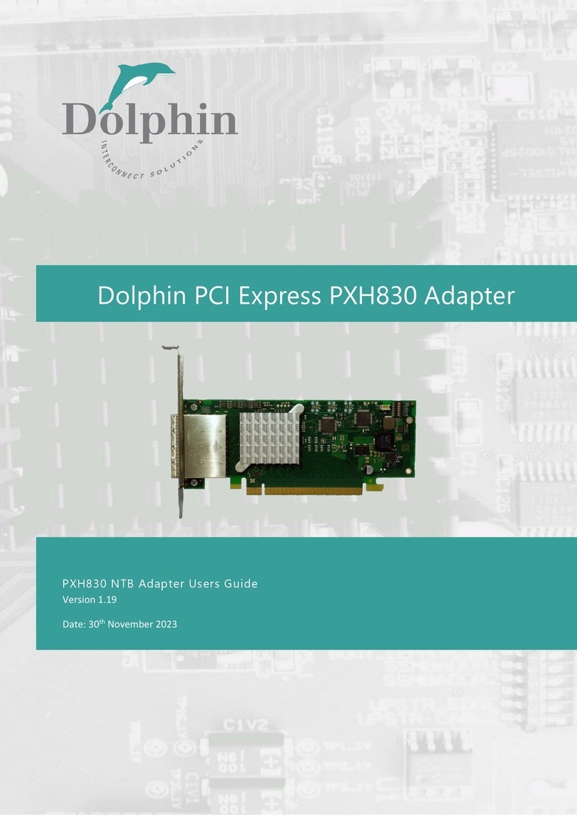
MXH830 HIGH LEVEL SPECIFICATION.......................................................................................................................... 5
MTBF BY TEMPERATURE AND ENVIRONMENT ...........................................................................................................................6
PACKAGING ................................................................................................................................................................ 6
PRE-INSTALLATION QUESTIONS.................................................................................................................................. 6
PCIE SLOT DETERMINATION................................................................................................................................................... 6
MXH830 NTB CONFIGURATION............................................................................................................................................7
OPERATING ENVIRONMENT....................................................................................................................................................7
CABLE CONNECTIONS............................................................................................................................................................ 7
Active Optical Cables (AOC) ......................................................................................................................................... 7
INSTALLATION ............................................................................................................................................................ 8
STEP 1-UNPACK BOARD .......................................................................................................................................................8
STEP 2-CHANGE PCIE BRACKET IF NECESSARY .......................................................................................................................... 8
STEP 3-CONFIGURE THE BOARD FOR PROPER OPERATION ..........................................................................................................8
STEP 4-INSTALL THE ADAPTER CARD....................................................................................................................................... 8
STEP 5-INSTALLING AND REMOVING THE CABLE........................................................................................................................ 8
Connecting the Cable................................................................................................................................................... 8
Supported Cables ......................................................................................................................................................... 8
Disconnecting the Cable .............................................................................................................................................. 9
STEP 6-INSTALLING THE DOLPHIN EXPRESSWARE SOFTWARE......................................................................................................9
STEP 7–VERIFY INSTALLATION &LEDS................................................................................................................................... 9
OPERATION ...............................................................................................................................................................10
CONFIGURATION AND DIP SWITCHES..................................................................................................................................... 10
DIP Switch Bank –Configuration ............................................................................................................................... 10
USE CASE A-2NODE CONFIGURATION –NTB MODE.............................................................................................................. 11
Connecting the cables for 2 Node Configurations, x16 link ....................................................................................... 11
Connecting the cables for 2 Node Configurations, x8 link ......................................................................................... 11
Connecting the cables for 2 Node Configurations, x4 link ......................................................................................... 12
USE CASE B-3NODE CONFIGURATION –NTB MODE.............................................................................................................. 13
Connecting the cables for 3 Node Configurations, x8 link ......................................................................................... 13
USE CASE C-5NODE CONFIGURATION –NTB MODE.............................................................................................................. 13
Connecting the cables for 5 Node Configurations, x4 link ......................................................................................... 13
USE CASE D–SWITCH CONFIGURATIONS –NTB MODE ...........................................................................................................14
EEPROM AND FIRMWARE UPGRADE ....................................................................................................................................15
IDENTIFYING THE CARD........................................................................................................................................................ 15
SUPPORT.............................................................................................................................. ERROR!BOOKMARK NOT DEFINED.
TECHNICAL INFORMATION ........................................................................................................................................18
BOARD REVISION HISTORY.................................................................................................................................................... 18
SIMPLIFIED SCHEMATICS ...................................................................................................................................................... 18
PCIE CABLE PORT SIGNALS ..................................................................................................................................................19
EXTERNAL PCIE X4CABLE CONNECTOR PIN-OUT .....................................................................................................................19
PCIE CABLE PORT MAPPING ................................................................................................................................................19
COMPLIANCE AND REGULATORY TESTING.................................................................................................................20
