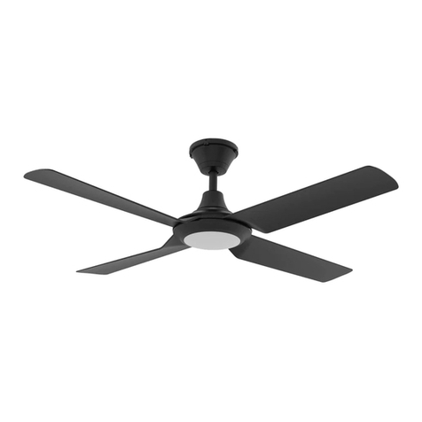
PROFAN-2 Date: 05/2018
Variant Item No. Descripon
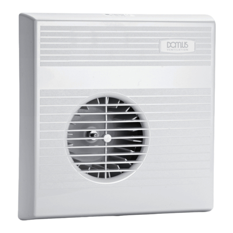
60010 PROFAN-2 3 in 1 Bathroom Heater, 2x275W heat lamp. White nish.
Thank you for purchasing your new LED PROFAN-2, Please take the me to read and understand the instrucon sheet below. Failure
to do so may void warranty.
FOR YOUR SAFETY:
• This product must be used only as described in this manual. Any other use not recommended by the manufacturer may cause re,
electric shock, or injury to persons. If you have quesons, contact the manufacture or local agent.
• All wiring must be carried out by a licensed electrician in accordance with all applicable naonal / local codes and standards. Also check
with the local council regulaons regarding installaon of exhaust fans.
• Ensure the power is OFF before the installaon.
• When cung into the ceiling material, care must be taken to ensure you do not damage electrical wiring and other hidden ulies
• The heater must be properly earthed/grounded.
• The lamps are extremely hot when in use. Do not touch the lamps with any part of your body when in use. Allow all lamps to cool
suciently before touching or replacement.
• For the purpose of avoiding any fumes leaking into your bathroom, the duct for the heater must not be laid together with ducts for
air-fuelled water heaters or other open-re appliances.
• Power cable used for wiring must be rated for a minimum 10A load.
IMPORTANT CONSIDERATIONS BEFORE INSTALLING
A few minutes planning can make a big dierence to the installaon me and also to your sasfacon with the funcon of your
Bathroom Heater.
• The unit must be installed in accordance with AS/NZS 3000, and all local building codes relang to damp locaons.
• Before commencing any cung, check in the ceiling space that there are no obstrucons such as ceiling joists and that there is sucient
height clearance (at least 220mm) for the housing. Check that the
• electrical wiring can be routed form the wall switches to the mounng locaon.
• Ceiling insulaon should be kept well clear of the unit and all ducng equipment.
• The unit should not be installed directly above a shower or bathtub.
• The unit must not be installed where it will be subject to direct splashing.
• Your Bathroom Heater is designed for installaon in at ceilings only. Don’t mount on a sloping ceiling or a vercal wall.
• The InfraRed lamps are not designed to heat the enre room area, they provide instant heat to persons standing directly below them.
Install your Bathroom Heater above the area where ‘drying o’ usually occurs.
• Your Bathroom Heater is not been designed for extended periods of operaon, as this could cause overheang and premature failure.
• For the exhaust fan to work eciently, replace air of a volume equivalent to what is being extracted must be able to enter the room. In
general this air would be drawn under the door, or through a slightly open window. If the room is airght, the fan will funcon poorly.
INSTALLATION
1. Your Bathroom Heater has been designed for use on ceilings between 2.4 and 2.7m in height.
2. The unit may be installed between joists using the built in clips. Alternavely the unit can be installed against a joist using a screw
through the ange plate.
3. Disassemble the unit before installaon. Remove the heat lamps from your Bathroom Heater. Unfasten the fascia-retaining springs
inside the housing. Unplug the LED at the connector and remove the fascia.
4. Mark the ceiling with a pencil outline 430mm x 250mm, and cut out a hole in the ceiling at the chosen area. Make sure a distance
between the edges and wall is no less than 400mm. There should be a minimum 220mm clearance above the unit.
5. Before commencing any cung, check in the ceiling space that there are no obstrucons such as ceiling joists, cables or pipes.
Specicaons
Voltage: 240V LED Type: 1x12W LED Panel, Switchable
3000K - 800lm
3000K - 900lm
Noise: 48dB
Motor: 35W Air Flow: 400m³/h Switch: 3 Gang
IP Rang: 20 Motor Speed: 1100rpm Warranty: 3 Year Replacement
Heat Lamp: 2x275W Infrared Fan Wheel: Ø160mm Duct size: Dia. 120mm


