Magnehelic®and Photohelic®are registered trademarks of Dwyer Instruments, Inc.
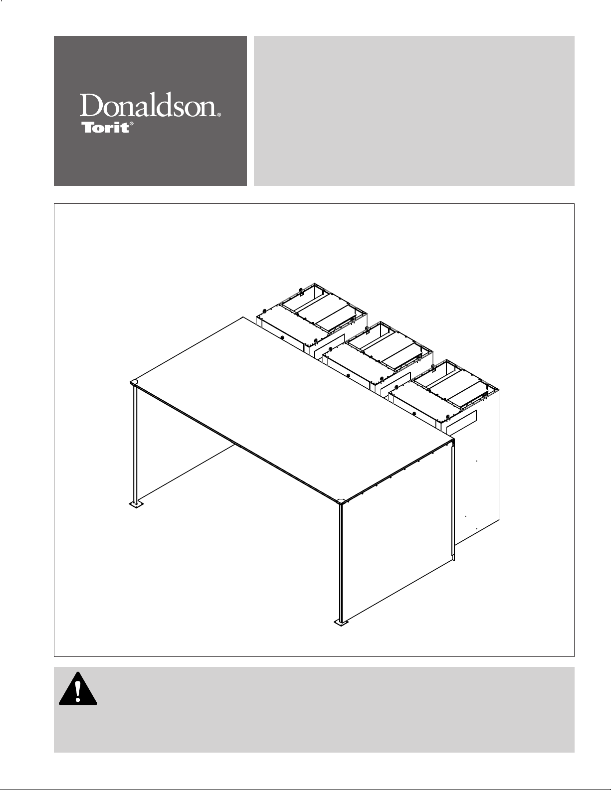
Downo Workstation, DWST 4-1 to 6-4
ii
Contents
IMPORTANT NOTES ............................................................................................................................................................................i
2 Product Description...................................................................................................................................................................3
3 Operation...................................................................................................................................................................................4
4 Product Service.........................................................................................................................................................................5
Operational Checklist .........................................................................................................................................................5
Dust Drawer........................................................................................................................................................................6
Filter Replacement .............................................................................................................................................................6
Light Bulb Replacement .....................................................................................................................................................7
Optional Afterlter Replacement.........................................................................................................................................7
Troubleshooting..................................................................................................................................................................8
Appendix A - Collector Installation................................................................................................................................................. A1
Collector Installation ........................................................................................................................................................ A2
Collector Location and Site Selection....................................................................................................................... A2
Provisional Anchor Bolt Recommendations ............................................................................................................. A2
Delivery and Inspection............................................................................................................................................ A3
DWST 4-1 and 6-1 Single Power Module Installation .............................................................................................. A4
DWST 4-2 to 4-4 and 6-2 to 6-4 Multiple Power Module Installation........................................................................ A5
Acoustic Hard Sided Booth Assembly ...................................................................................................................... A6
Soft Sided Acoustical Booth Assembly..................................................................................................................... A8
Compressed Air Installation...................................................................................................................................... A9
Electrical Wiring........................................................................................................................................................ A9
Solid-State Timer Installation..........................................................................................................................................A11
Optional Equipment....................................................................................................................................................... A15
Magnehelic®Gauge ............................................................................................................................................... A15
Photohelic®Gauge ................................................................................................................................................ A16
Delta P Control ...................................................................................................................................................... A18
Delta P Plus Control............................................................................................................................................... A18
Light Fixture ........................................................................................................................................................... A18
Afterlters ............................................................................................................................................................... A18
Acoustic Curtain for Power Module ........................................................................................................................ A19
Chamber Silencer................................................................................................................................................... A19
IEC Control Panel with Programmable Logic Control ............................................................................................ A20
IEC Control Panel Installation ................................................................................................................................ A22
Sprinkler ................................................................................................................................................................. A23
Start-Up/Commissioning Collector ................................................................................................................................ A24
Decommissioning Collector........................................................................................................................................... A26
Product Information ....................................................................................................................................................... A27
Service Notes ................................................................................................................................................................ A28
Donaldson Industrial Air Filtration Warranty................................................................................................................................ A30