3
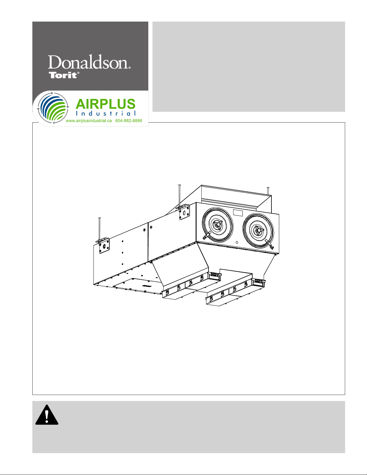
Donaldson Company, Inc.
Inspection on Arrival
1. Inspect unit on delivery.
2. Report any damage to the delivery carrier.
3. Request a written inspection report from the Claims
Inspector to substantiate claim.
4. File claims with the delivery carrier.
5. Compare unit received with description of product
ordered.
6. Report incomplete shipments to the delivery carrier
and your Donaldson representative.
7. Remove crates and shipping straps. Remove loose
components and accessory packages before lifting
unit from truck.
8. Check for hardware that may have loosened during
shipping.
9. Use caution removing temporary covers.
Installation Codes and Procedures
Codes may regulate recirculating
filtered air in your facility.
Consult with the appropriate authorities
having jurisdiction to ensure compliance
with all national and local codes regarding
recirculating filtered air.
Safe and efficient operation of the unit depends on
proper installation.
Authorities with jurisdiction should be consulted
before installing to verify local codes and installation
procedures. In the absence of such codes, install unit
according to the National Electric Code, NFPA No.
70-latest edition and NFPA 91 (NFPA 654 if combustible
dust is present).
A qualified installation and service agent must complete
installation and service of this equipment.
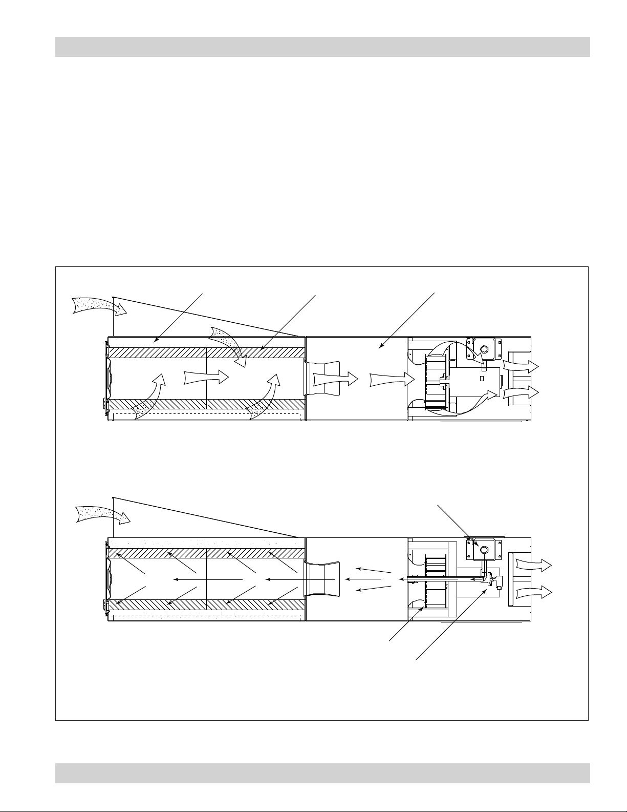
All shipping materials, including shipping covers, must be
removed from the unit prior to, or during unit installation.
Failure to remove shipping
materials from the unit will
compromise unit performance.
Inspect unit to ensure all hardware is properly installed
and tight prior to operating collector.
Installation
Site selection must account
for wind, seismic zone, and
other live-load conditions when selecting the
location for all units.
Codes may regulate acceptable locations for
installing dust collectors. Consult with the
appropriate authorities having jurisdiction to
ensure compliance with all national and local
codes regarding dust collector installation.
Site Selection
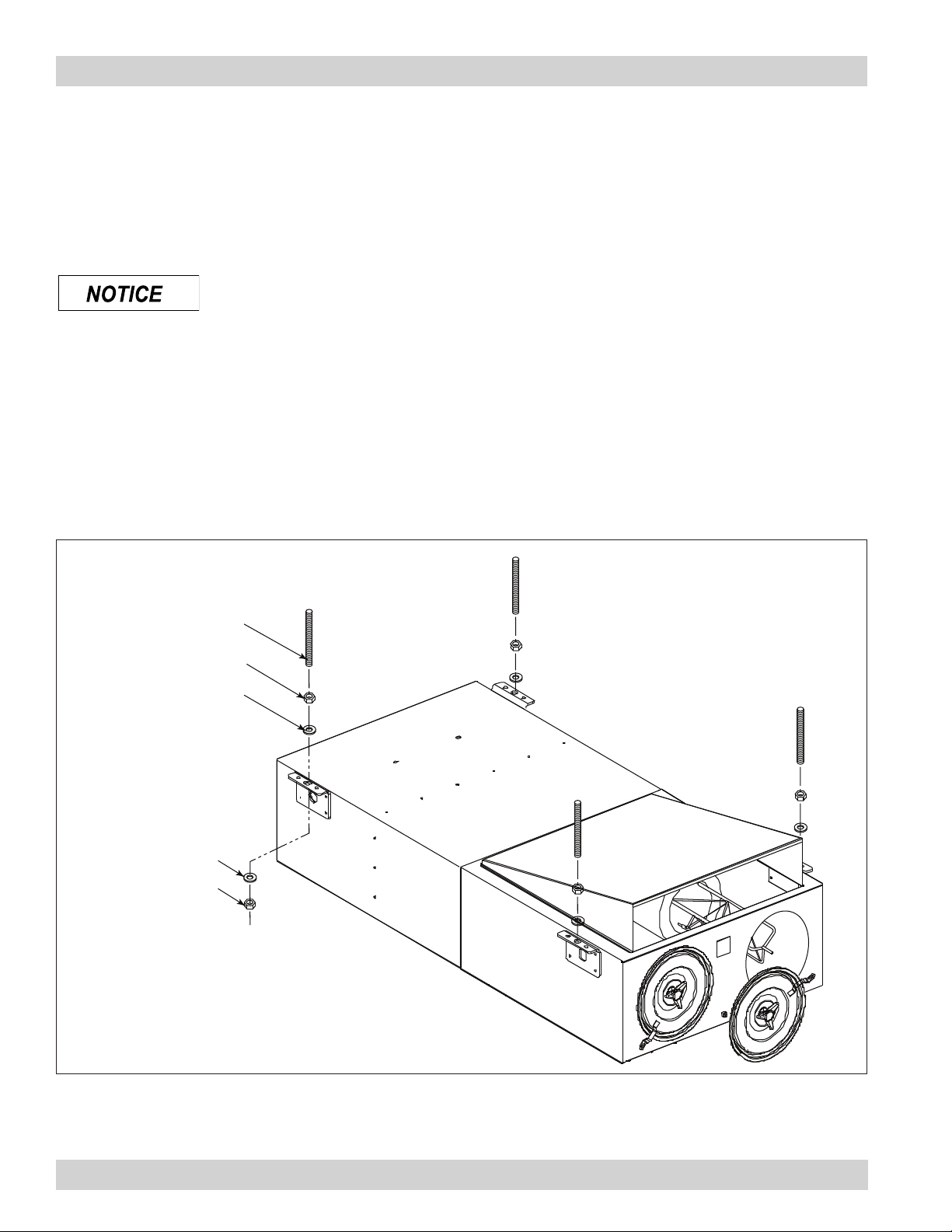
1. The unit can be suspended or hung from overhead
supports. The supports must be adequate to carry
the live load of the unit and installation performed to
reduce sway or vibration to the unit.
2. Provide clearance from heat sources and
interference with utilities when selecting the location
for suspended units. Reference the Specification
Control Drawing shipped with the unit.
Unit Location
Donaldson Torit equipment is not
designed to support site-installed
ducts, interconnecting piping, or electrical
services. All ducts, piping, or electrical
services supplied by others must be adequately
supported to prevent severe personal injury
and/or property damage.
When hazardous conditions or materials are
present, consult with local authorities for the
proper location of the collector.
Foundation or roof support must be capable of supporting
the entire weight of the unit, plus the weight of the
collected material, piping, and ductwork.
Locate the collector to ensure easy access to electrical
and compressed-air connections, and routine
maintenance.
If explosion protection devices are part of the system,
locate the collector in accordance with the local code
requirements (Example: NFPA 654).