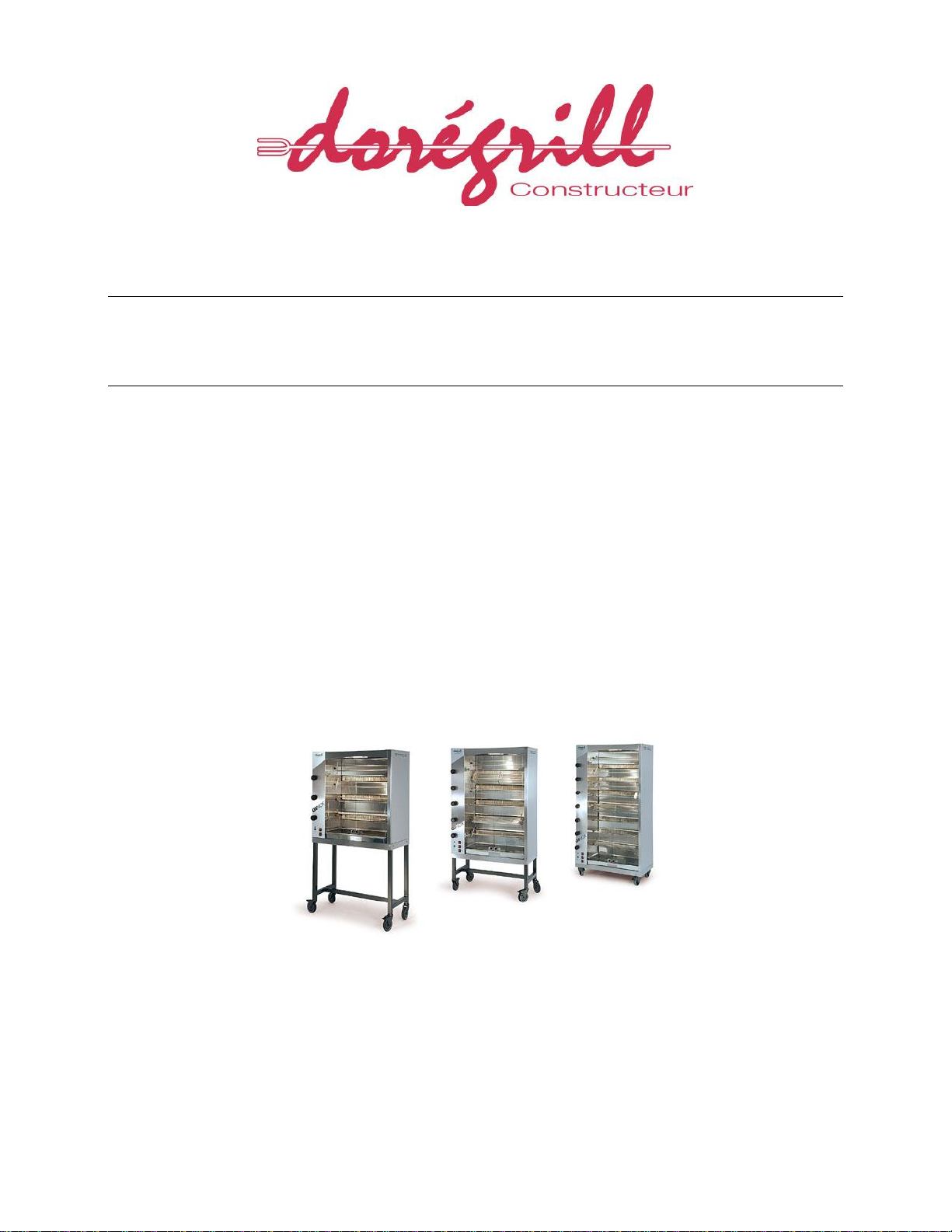
USER GUIDE ROTISSERIE OVEN GINOX ELEC
TABLE OF CONTENTS
INFORMATION FOR THE USER
1GENERAL POINTS...................................................................................................................................................5
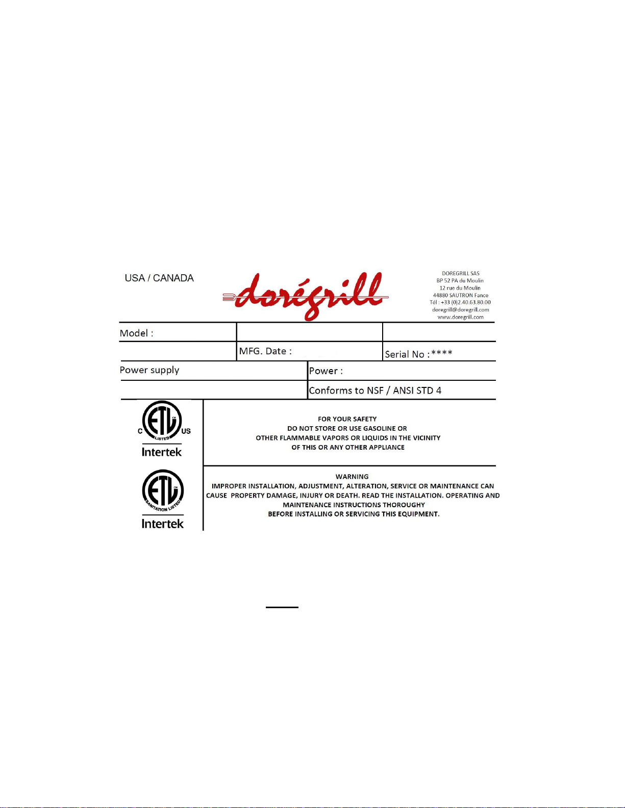
1.1 LABELLING.........................................................................................................................................................................5
1.2 THE IMPORTANCE OF THE MANUAL ......................................................................................................................................6
1.3 GENERAL PRECAUTIONS.....................................................................................................................................................6
1.4 GUARANTEE ......................................................................................................................................................................6
2TRANSPORT AND HANDLING .................................................................................................................................7
2.1 TRANSPORT AND DELIVERY.................................................................................................................................................7
2.2 UNPACKING AND HANDLING.................................................................................................................................................7
3TECHNICAL DESCRIPTION......................................................................................................................................7
3.1 GENERAL DESCRIPTION ......................................................................................................................................................7
3.2 PARTS LIST........................................................................................................................................................................8
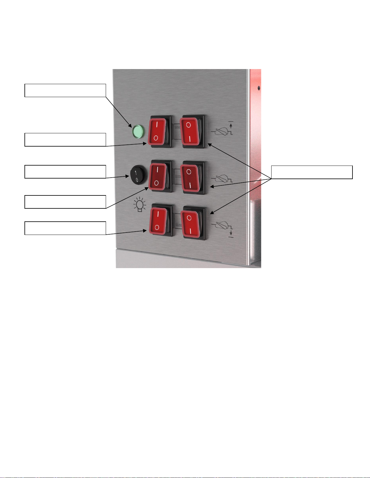
3.3 CONTROL PANEL................................................................................................................................................................9
3.4 DIMENSIONS OF THE ROTISSERIE ........................................................................................................................................9
3.5 TECHNICAL DATA................................................................................................................................................................9
3.6 EMPLOYMENT DESTINATION ................................................................................................................................................9
3.7 ELECTRICAL DIAGRAM ........................................................................................................................................................9
4INSTALLATION......................................................................................................................................................10
4.1 GENERAL INSTRUCTIONS ..................................................................................................................................................10
4.2 INSTALLATION ..................................................................................................................................................................10
4.3 ELECTRICAL CONNECTIONS...............................................................................................................................................10
4.4 EVACUATION OF VAPORS ..................................................................................................................................................10
5USE.......................................................................................................................................................................12
5.1 CONTROLS ......................................................................................................................................................................12
5.2 IMPLEMENTATION .............................................................................................................................................................13
6MAINTENANCE .....................................................................................................................................................14
6.1 DAILY AFTER COOKING .....................................................................................................................................................14
6.2 WEEKLY CLEANING...........................................................................................................................................................14
6.3 END OF SEASON CLEANING (OR SEMI-ANNUAL)...................................................................................................................14
7TEMPERED GLASS WINDOWS –MAIN CAUSE OF BREAKAGE.............................................................................15
7.1 THERMAL SHOCK..............................................................................................................................................................15
7.2 IMPACTS ON THE GLASS....................................................................................................................................................15
7.3 HANDLING .......................................................................................................................................................................15
8TECHNICAL CHARACTERISTICS...........................................................................................................................16
9MAINTENANCE / CUSTOMER SERVICE .................................................................................................................17
9.1 PROBLEM LOCALISATION ..................................................................................................................................................17
9.2 SPECIFIC REPAIRS............................................................................................................................................................18
9.2.1 Changing a bulb...................................................................................................................................18
9.2.2 Opening the technical cabinet..............................................................................................................18
9.2.3 Changing the direction of rotation of a spite drive motor....................................................................18
10 ILLUSTRATED COMPOSITION TABLE ...............................................................................................................19
10.1 PICTURE 1–THE TROLLEY ...............................................................................................................................................19
10.2 PICTURE 2–BACK OPENING.............................................................................................................................................20
10.3 PICTURE 3–DOORS ........................................................................................................................................................20