
2 Crane 4000LE 07-2022RL6002-001
Crane 4000LE Installation Manual
In-ground Motion Assist 360 drive and speed control
Remote control enclosure
Table of Contents
Table of contents
General information
Product description and technical
information
. Crane LE series
. Available options
. Motion Assist technical information
. LE series model comparison
Safety information
. Safety Warnings
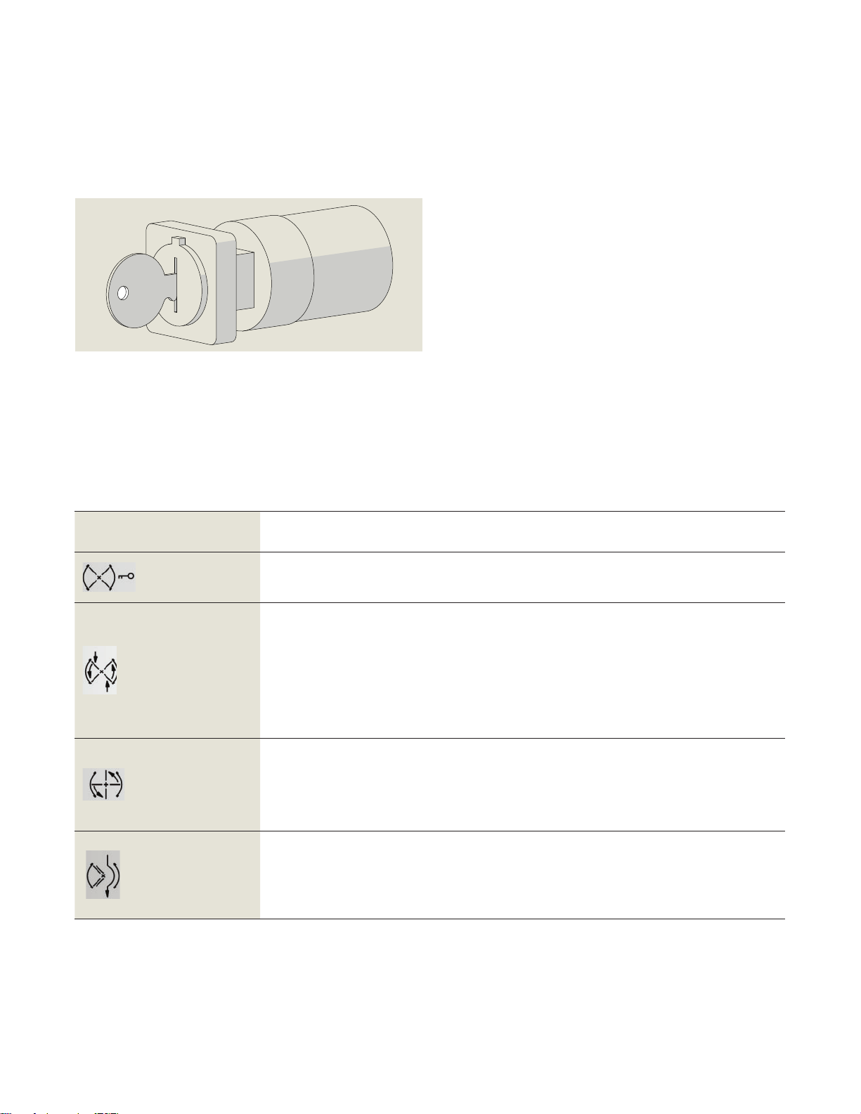
Operator components
. Mode switch
. Emergency Stop pushbutton
.. Triggering an Emergency Stop
.. Start up after an Emergency Stop
. Service panel (option)
. Wave to Open, Push to Start plates (option)
. Fault LED
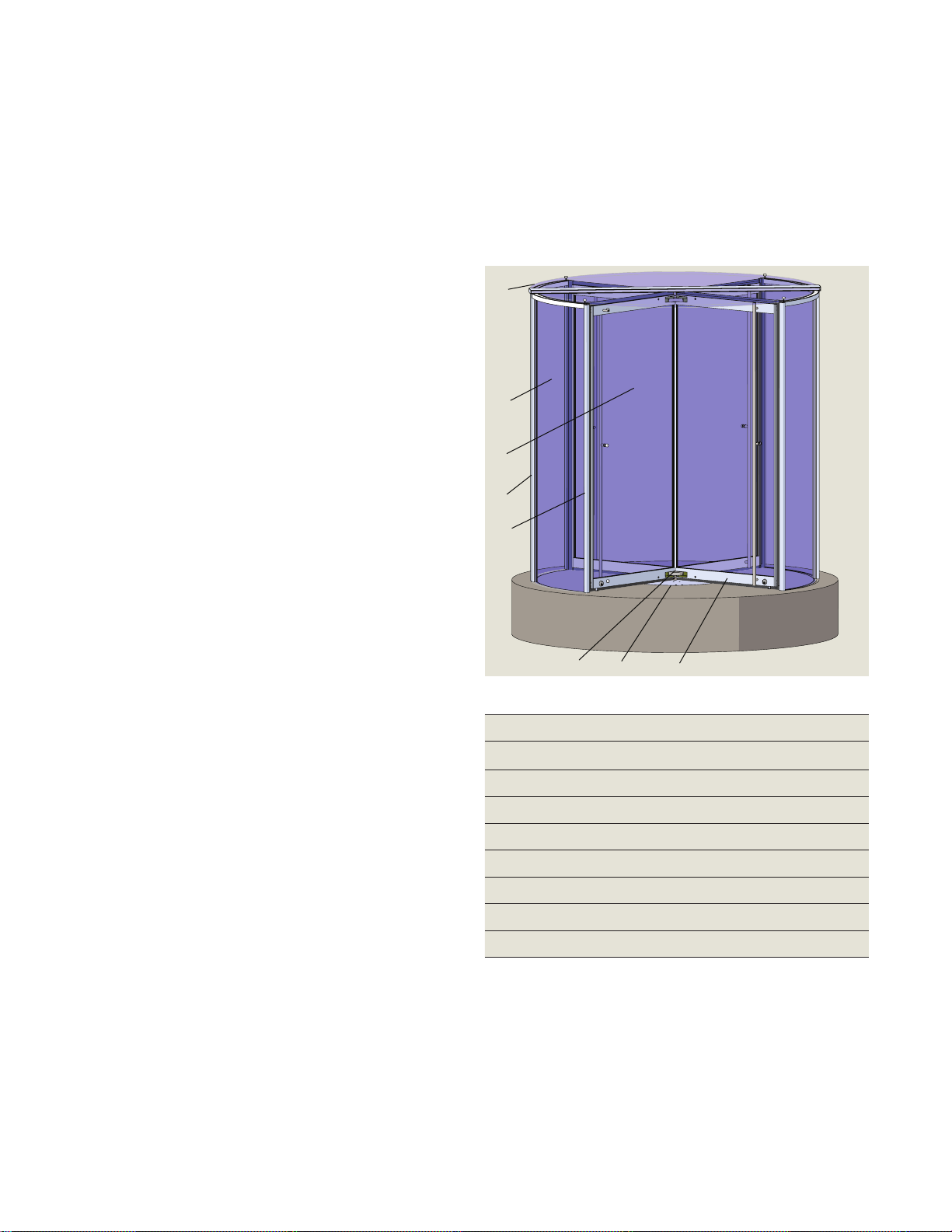
Revolving door assemblies
. Door configurations
In-ground Motion Assist drive and speed
control
. Glass canopy with muntin assembly
. Muntin and bearing assembly
. Glass canopy with bearing assembly
. wing steel shaft assembly, floor drive/speed
control RS-
. wing steel shaft assembly, floor
drive/speed control RS-
. Hanger assembly, steel shaft RS-X
. Bookfold mechanism
. Enclosure posts
. LE door wing assembly example
. Door wing types
. Header bar assembly
. Floor bar assembly and base clips
. Motion Assist in-ground drive
assembly RS
. In-ground speed control assembly
. Motion Assist drive bracket assembly
. Remote enclosure – Motion Assist
power supply and control unit
. Floor grill and pan assembly (option)
. Uninterruptible Power Supply (UPS)
(option)
In-ground container hardware
. In-ground container assembly
. Motion Assist extension cables to
remote enclosure
. Motion Assist earth grounding cable
. Service panel communication cable
. In-ground container assemblies with
fastener hardware
. Container lids and cover assemblies
Recommended Tools And Materials
. Recommended tools
. Recommended installation materials and
installation hardware
Assembly safety
. Assembly safety
. Cordon off work area
Prepare finished floor
. Assembly location
. Preparing finished floor for revolving door
assembly
Floor template
Mark revolving door location on
sub floor, install base rail assemblies
. Mark door centerpoint
. Mark door base rail locations, install base
rail assemblies
. Floor base clips and rail assembly –
mounting to sub floor
. Floor clip shimming
Install leveling plate in pit, install
container in pit
. Pit location and dimensions
. Crane Shop drawing, pit dimensions for
in-ground container
. Install leveling plate in pit
. Orientation of in-ground container in pit –
building interface
. Conduit in pit for building wiring – overview
. Determine in-ground container conduit
adapter position in pit
. Container drain: locate and drill hole for
through-wall pipe fitting
. Container drain hole location dimensions
using leveling plate
. Check hole alignment of container covers
on container flange
. Install cable ties
. Install in-ground container in pit


 user manual")


