Dormakaba Crane 4000LE User manual

Crane 4000LE
In-ground Motion Assist 360 drive and speed control
Remote control enclosure
Owner's Manual
RL6002-002 – 07-2022
| EN |

2 Crane 4000LE 07-2022RL6002-002
Crane 4000LE Owner's Manual
In-ground Motion Assist 360 drive and speed control
Remote control enclosure
Table of Contents
Table of contents
General information
To our customers
What you should know
. Distributor information
Safety
. Intended use
. Danger points of the revolving door
Operator components
. Emergency Stop pushbutton
.. Triggering an Emergency Stop
.. Start up after an Emergency Stop
. Mode switch
. Fault LED
. Service panel (option)
. Wave to Open plate (option)
Revolving door assembly
. Revolving door assembly components
overview, wing door
. In-ground container and Remote control
enclosure
. Steel shaft assembly, Job ID tag
Bookfold
Speed control
Maintenance
. Door and floor maintenance
. Weathersweeps
. Motion Assist drive warning sign
. In-ground container drain
. Cleaning surfaces
Table of contents

3Crane 4000LE 07-2022RL6002-002
Crane 4000LE Owner's Manual
In-ground Motion Assist 360 drive and speed control
Remote control enclosure
Chapters 1,2 and 3
. Owner's Manual
This Owner's manual applies to Crane LE manual
revolving doors with:
• In-ground (low profile) Motion Assist drive with
remote control enclosure.
• In-ground speed control.
. Manual storage.
This document must be kept in a secure place, and
accessible for reference as required.
. dormakaba.us website.
Manuals are available for review, download, and printing
on dormakaba.us website.
. Dimensions
Unless otherwise specified, all dimensions are given in
inches (“).
General information
To our customers
We are pleased that a Crane LE (low energy)
manual revolving door has been selected for this
installation. Crane designed, tested and built the system
to provide many years of service.
The purpose of this manual is to provide you information
regarding your Crane LE revolving door. This
includes safety and maintenance information.
It is essential that you recognize the importance of
maintaining your door.
What you should know
.. dormakaba USA, Inc. distributor information.
Be sure that the dormakaba USA, Inc. distributor has
provided the following information for this revolving
door installation:
. Crane Owner's Manual RL-.
. Discussion of problems that could result from door
operation after a malfunction observed.
. Number to call for service or questions about your
revolving door if you are uncertain of any condition or
situation.
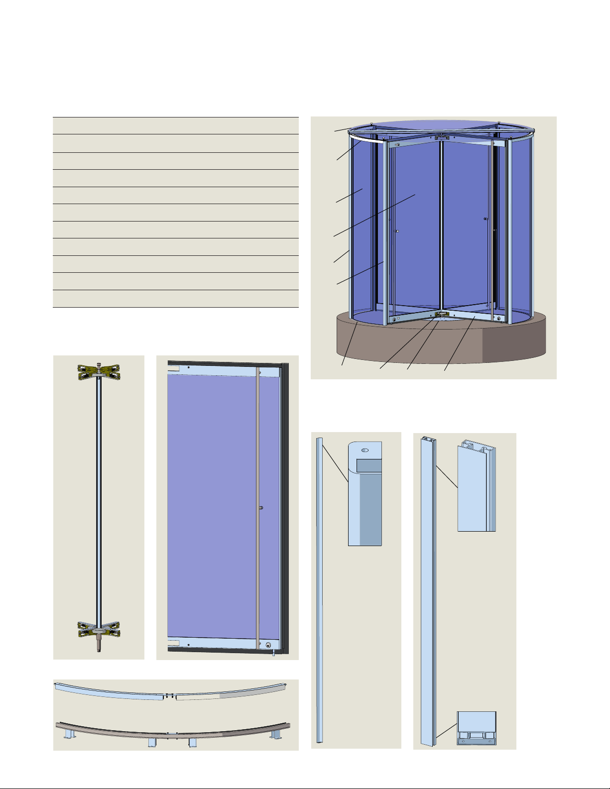
. Location of job number tag on door steel center
shaft assembly.
• Reference Chapter ..
. Distributor information
. Location of Vac circuit breaker for
Motion Assist power supply.
• Reference Paragraph ., remote control enclosure.
. Exit location of in-ground container drain tube or
pipe.
• Reference Chapter , Maintenance information.
WARNING
If there are any problems, discontinue door
operation immediately and secure the door in
a safe manner.
Call your local dormakaba USA, Inc.
distributor for repair.
It is your responsibility as owner and caretaker of the
equipment, to inspect the operation of your door system
to insure that it is safe for use by your customers and
employees.
Call your local dormakaba distributor for repair. The
distributor is trained to service the revolving door using
the applicable dormakaba USA, Inc. Installation Manual.
. Service availability.
dormakaba USA, Inc. has a nationwide network of
authorized distributors for sales, installation and service
of its products.
. Symbols used in this manual.
WARNING
This symbol warns of hazards which could result
in personal injury or threat to health.
NOTICE
Draws attention to important information
presented in this document.
CAUTION
Warns of a potentially unsafe procedure or
situation.

4 Crane 4000LE 07-2022RL6002-002
Crane 4000LE Owner's Manual
In-ground Motion Assist 360 drive and speed control
Remote control enclosure
Chapter 4
.. Intended use.
The Crane LE revolving doors are designed as or
wing revolving doors for use as a doorway for people to
pass through at entrances and in the interior of
buildings.
.. Wing breakout.
The revolving door wings can be pushed open manually
for emergency egress.
• Reference Chapter : Bookfold.
WARNING
In case of emergency, revolving door can be
used as an exit, but it is not the primary path of
egress.
The side door(s) should be used!
. Danger points of the revolving
door
When passing through the revolving door, people may
be at risk for injury at the locations referenced in
Fig. ...
Fig. 4.2.1 Revolving door danger points
1Secondary closing
edge floor
2Secondary closing
edge ceiling
3Opposing closing
edge
4Main closing edge
inner wall
5Wings rotating in a
counterclockwise
direction
5
1
4
3
2
Safety
WARNING
Danger of misuse!
Misuse of the revolving door can cause
dangerous situations.
• Children should never be allowed to enter the
revolving door without adult supervision/
accompaniment.
• Children should never be allowed to play in
front of the entrance and exit of the revolving
door or inside of the revolving door itself.
• Do not install the revolving door over soft
flooring (e.g., carpet).
• Never mount or hang objects on the revolving
door.
• Never stop or block the revolving door with an
object.
• Customer - Do not operate the revolving
door until door has been commissioned by
dormakaba service technicians (Para...).
• Do not walk through the revolving door with
bulky objects.
• Do not walk against the wing rotation
direction of the revolving door.
• Do not operate the revolving door if there is
insufficient lighting.
• Do not operate the revolving door if it is
damaged (e.g., broken glass).
• Never use replacement parts that are not
approved by dormakaba.
• People cannot be allowed to stay in the
revolving door for longer than it takes to pass
through the door.
. Intended use
.. Revolving door operation.
NOTICE
The customer can only operate the revolving
door after door commissioning by dormakaba
service technicians.

5Crane 4000LE 07-2022RL6002-002
Crane 4000LE Owner's Manual
In-ground Motion Assist 360 drive and speed control
Remote control enclosure
Chapter 5
. Emergency Stop pushbutton
Fig. 5.1.1 Emergency Stop pushbutton
.. Emergency Stop pushbutton locations.
• Building interior on the leading door quarter post.
• Second Emergency stop pushbutton located on the
building exterior.
.. Actuation of Emergency Stop pushbutton.
. A time delay disconnection of the Motion Assist
drive output stage is performed (approximately two
seconds).
. During this time delay the drive performs a fast
braking of the door to a standstill.
. After the time delay the drive output stage is
switched off and door can then be turned manually.
.. Emergency Stop pushbutton reset.
• Emergency Stop pushbutton is reset by pulling or
turning the button.
.. Triggering an Emergency Stop
WARNING
Risk of injury due to deactivated safety
equipment!
After the emergency stop is activated, the drive
is unlocked. Safety devices are no longer in
operation. This can cause serious injuries if
attempts are made to turn the door manually.
• Before turning door manually, check to make
sure no one could be injured.
• If people have been locked into the revolving
door, carefully turn the door until the people
are able to exit the door.
• When turning the door manually, make sure
there are no limbs between the closing
edges.
.. Start up after an Emergency Stop
WARNING
Risk of injury due to automatic startup of
revolving door!
The revolving door can set itself in motion
automatically. If there are people in the door,
they may be at risk of injury.
• Release the Emergency Stop button only
when there are no longer any people in the
revolving door.
... Procedure after an Emergency stop.
. Cause for the emergency stop has been removed.
. Reset the Emergency stop pushbutton by turning or
pulling the pushbutton.
. Door will move to the home position.
. The revolving door will continue with the current
program settings.
Operator components

6 Crane 4000LE 07-2022RL6002-002
Crane 4000LE Owner's Manual
In-ground Motion Assist 360 drive and speed control
Remote control enclosure
Chapter 5
. Mode switch
Fig. 5.2.1 Mode switch with key lock .. Mode switch
• The Mode switch is located inside the building on the
leading quarter post or attached separately within
sight of the revolving door.
• A key or code secures the Mode switch against
unauthorized access.
.. Low energy speed definition -
ANSI/BHMA A..
Door speed resulting in a maximum of . lbf-ft [. Nm]
of kinetic energy.
5.2.3 Knowing act.
Consciously activating a switch with the knowledge of
what will happen such as starting, slowing or stopping a
revolving door.
Switching devices may include wall or jamb-mounted
contact switches such as push plates, fixed contact
switches and controlled access devices such as keypads,
card readers, and key switches.
.. Mode switch (low-energy) functions.
Mode switch
position Function
Off • Revolving door will stay in the home position.
• After a set period of time, any internal lighting is switched off.
AUTOMATIC
• A knowing act (Para. ..) switch starts rotary movement of the door wings at
low energy speed (Para. ..). Acceleration to walking speed is done manually.
• Manually pushing the door starts rotary movement of the door wings at low
energy speed. Acceleration to walking speed is done manually.
• Revolving door automatically stops in the next starting position as soon as it is
no longer manually operated.
AUTOMATIC
• Door rotates continuously at a low energy speed. Acceleration to walking speed
is done manually.
• After door passage, the door slows down to low energy speed and continues to
rotate at low energy speed.
Summer
• Revolving door stops at its starting position and the drive is unlocked.
• Door wings can be rotated manually.
• Bookfold: wings can be folded to the side.

7Crane 4000LE 07-2022RL6002-002
Crane 4000LE Owner's Manual
In-ground Motion Assist 360 drive and speed control
Remote control enclosure
Chapter 5
. Wave to Open plate (option)
.. Wave to Open plate.
Locations:
• Inside the building on the leading quarter post/end
wall or attached separately within sight of the
revolving door.
• Building exterior.
Plates must be located per
ANSI BHMA A., Power and Manually Operated
Revolving Pedestrian Doors.
Plate starts rotary movement of the door wings at low
energy speed (Para. ..).
. Service panel (option)
.. Service panel.
• Typically located on side of leading quarter post.
• For use by dormakaba service personnel.
1RJ45 cover
Fig. 5.4.1 Service panel
DX4604-08C
1
.. Fault LED.
• Fault LED provides Error number indication.
• Frequency and rate of LED flashes indicates Error
number.
.. Fault LED location
• Field installed above or below Mode switch.
.. Error number and LED blinking codes.
• First digit of Error number: slowly flashing LED
(approximately Hz).
• Second digit of Error number: rapidly flashing LED
(approximately Hz).
• Error LED fault code example:
x slow and x fast = Error no.
(braking distance at safety stop too long).
TIPS AND RECOMMENDATIONS
Reference Wiring, Setup and Troubleshooting
manual RL6002-003 for fault codes.
. Fault LED
Fig. 5.3.1 Fault LED RX6013-001
Fig. 5.5.1 Waveto Open
plate
DX3331-001
Fig. 5.5.2 Push to Start plate ,
1.5 x 4.75",
DX3339-040

8 Crane 4000LE 07-2022RL6002-002
Crane 4000LE Owner's Manual
In-ground Motion Assist 360 drive and speed control
Remote control enclosure
Chapter 6
. Revolving door assembly components overview, wing door
Fig. 6.1.1 Steel shaft
assembly, 4
wing door Fig. 6.1.2 Wing assembly example
Fig. 6.1.4 4 wing 4000LE 4 wing revolving door
# Description
Center shaft assembly
Wing assembly
Center post
Quarter post/end wall
Glass canopy assembly
Wing glass
Enclosure glass
In-ground low profile container
Header bar assembly
Floor bar assembly with floor clips
Table 6.1.1 Crane 4000LE assemblies and parts
Fig. 6.1.5 Quarter
post/end
wall Fig. 6.1.6 Center post
Fig. 6.1.3 Header and floor bars
12
3
4
5
6
7
8
9
10
Revolving door assemblies

9Crane 4000LE 07-2022RL6002-002
Crane 4000LE Owner's Manual
In-ground Motion Assist 360 drive and speed control
Remote control enclosure
Chapter 6
Fig. 6.2.1 In ground container assembly, low profile
. In-ground Motion Assist assembly and Remote control enclosure
Fig. 6.2.2 Remote control enclosure RK6007
Fig. 6.2.3 Motion Assist 360 drive
Fig. 6.2.4 Identification label Motion Assist 360 drive
2
3
1
Art.Nr.: 34050001150
100 - 240V ~ 50/60 Hz
-40 - +60°C
5
3
540
DIN 18650
Made in Germany
DORMA Deutschland GmbH
Dorma Platz 1
58256 Ennepetal
Germany
IP20
month year
System:
Speed Limiter:
Positioning Automatic:
Static force:
Servomatic:
Static force:
Automatic:
Static force:
58 W
8 W
150 N
67 N
58 W
67 N
1/2/3
0
102 W
KT FLEX Direct drive system
# Description
Remote control enclosure RS-
Motion Assist power supply RX
Motion Assist control unit RX
In-ground speed control RS-
Container assembly weldment RS
Leveling plate assembly RS
Motion Assist drive
RX
Identification label
Drain fitting RC
Outer cover assembly RS
Container lid, center section RC
Conduit adapter, DC wiring RC-
Bottom plug adapter, in-ground drive/
speed control LP RC
Table 6.2.1 In-ground container and Remote enclosure
10
11
Art.Nr.:34050001150
100- 240V ~ 50/60 Hz
-40- +60°C
5
3
540
DIN18650
Madein Germany
DORMADeutschland GmbH
DormaPlatz 1
58256Ennepetal
Germany
IP20
month year
System:
SpeedLimiter:
PositioningAutomatic:
Staticforce:
Servomatic:
Staticforce:
Automatic:
Staticforce:
58W
8W
150N
67N
58W
67N
1/2/3
0
102W
KTFLEX Direct drive system
5
9
12
13
13
14
15
16
4
10

10 Crane 4000LE 07-2022RL6002-002
Crane 4000LE Owner's Manual
In-ground Motion Assist 360 drive and speed control
Remote control enclosure
Chapters 6 and 7
. Bookfold mechanism.
• This hardware complies with all state and federal
requirements for providing emergency egress.
• The pressure required to engage the bookfold
mechanism is adjustable to meet
ANSI/BHMA A., Power and Manual Operated
Revolving Pedestrian Doors.
WARNING
In case of emergency, revolving door can be used
as an exit, but it is not the primary path of
egress.
The side door(s) should be used!
Bookfold
Fig. 7.1 Bookfold mechanism
. Steel shaft assembly, Job ID tag
Fig. 6.3.1 Steel center shaft job ID tag location
Fig. 6.3.2 Job ID tag
CRANE REVOLVING DOORS ™
JOB #
1
1Job tag RD6001

11Crane 4000LE 07-2022RL6002-002
Crane 4000LE Owner's Manual
In-ground Motion Assist 360 drive and speed control
Remote control enclosure
Chapter 8
Speed control
. Speed control.
Unit is mounted in the in-ground container.
• A centrifugal force brake slowly engages as the door
reaches the maximum allowable RPM set by
ANSI/BHMA A., Standard for Power and
Manual Operated Revolving Pedestrian Doors.
WARNING
Speed control maintenance or service must only
be done by dormakaba technicians!
Fig. 8.2 Speed control
Fig. 8.1 In-ground drive and speed control
1Speed control
2Motion Assist 360
drive
3DC conduit adapter
Adapter may be a
different position on
container
1
2
3

12 Crane 4000LE 07-2022RL6002-002
Crane 4000LE Owner's Manual
In-ground Motion Assist 360 drive and speed control
Remote control enclosure
Chapter 9
. Door and floor maintenance
Maintenance
Fig. 9.1.1 4 wing revolving door .. Floor maintenance.
. Keep floor surface clean and free of dirt and debris.
.. In-ground container.
. Keep floor cover plates free of dirt and debris.
. Check that in-ground container floor cover plates are
secure.
• Do not use a screw gun to check fasteners for
tightness.
• If required, use only a Phillips screwdriver to check
that fasteners are snugged down.
. Clean any debris present at the center shaft bottom
plug hole in cover plates.
.. Mechanical lock cylinder and floor strikes.
. Keep lock cylinders and floor strikes free of dirt and
debris.
.. Door glass maintenance.
. Clean all glass surfaces with commercially available
glass cleaners.
1Floor cover plate
2Center shaft bottom
plug
3Lock cylinder assembly
4Floor strike
5Center shaft
. Weathersweeps
1
Fig. 9.2.1 T-style weathersweep
1 T-style
weathersweep
2
Fig. 9.2.2 Horsehair weathersweep
2 Horsehair
weathersweep
.. Weathersweep maintenance.
NOTICE
Reducing or trimming the size of the bottom
sweep makes the sweep more rigid and voids
all warranties.
. Inspect condition of sweeps.
• Recondition horsehair sweeps if possible using
conditioner.
. Replace weathersweeps as required.
• Contact dormakaba distributor for replacement
weathersweeps.
33
44
125

13Crane 4000LE 07-2022RL6002-002
Crane 4000LE Owner's Manual
In-ground Motion Assist 360 drive and speed control
Remote control enclosure
Chapter 9
. Motion Assist drive warning sign
WARNING
For dormakaba installation and maintenance
personnel.
This sign is located on the Motion Assist
drive (Fig. ..) and warns of the hazards for
people with pacemakers and other active
medical implants.
Strong electromagnetic or magnet fields may
be present in the vicinity of this sign. These
fields may disrupt pacemakers or other
medical implants or cause them to
malfunction. People wearing pacemakers and
other active medical implants should not
approach components with this safety
warning.
People with pacemakers and other active
medical implants should not come within
20 inches [51 cm] of the Motion Assist 360 drive.
Art.Nr.:34050001150
100- 240V ~ 50/60 Hz
-40- +60°C
5
3
540 DIN18650
Madein Germany
DORMADeutschland GmbH
DormaPlatz 1
58256Ennepetal
Germany
IP20
month year
System:
SpeedLimiter:
PositioningAutomatic:
Staticforce:
Servomatic:
Staticforce:
Automatic:
Staticforce:
58W
8W
150N
67N
58W
67N
1/2/3
0
102W
KTFLEX Direct drive system
Fig. 9.3.1 Motion Assist 360 drive
.. Motion Assist drive.
Motion Assist drive is installed in the revolving door
in-ground container (Fig. ..).
.. Pacemaker warning sign.
Fig. 9.3.2 In-ground container with Motion Assist 360
drive, covers removed
1In-ground container
2Motion Assist 360
drive
21

14 Crane 4000LE 07-2022RL6002-002
Crane 4000LE Owner's Manual
In-ground Motion Assist 360 drive and speed control
Remote control enclosure
Chapter 9
.. In-ground container drain maintenance.
. In-ground container drain fitting () is connected to
customer-supplied and installed drain tube or
pipe (.).
. This tube or pipe must be connected to building drain
system.
NOTICE
Drain tube or pipe maintenance.
• Insure drain tube or pipe exit is free of dirt
and debris.
. In-ground container drain Fig. 9.4.1 In-ground container drain and
customer drain tube or pipe
6In-ground container
through wall drain
fitting - Drain fitting
may be in a different
location on container
6.1 Customer supplied and
installed drain tube or
pipe
66.1
. Cleaning surfaces
.. Aluminum
. Dust and grime can be removed by regular cleaning.
• Use a mild, non-abrasive soap or cleaning solution
and water.
• After cleaning, surfaces should be wiped dry with a
clean absorbent material.
. Tar and built-up dirt can be removed with solvent
cleaners such as turpentine if followed by a soap and
water cleaning and fresh water rinse.
NOTICE
Avoid acid or alkali cleaners; they may attack
the anodized finish.
• After cleaning, surfaces should be wiped dry with a
clean absorbent material.
.. # stainless steel
. For routine cleaning, use soap, ammonia, or
detergent and water.
• Always working in the direction of the grain, rub with
a sponge or rag.
• Rinse with water, wipe dry.
. Stubborn dirt or grime can be removed with a quality
commercial stainless steel cleaner.
.. Mirror finish stainless steel
NOTICE
Mirror finishes require very special care.
Abrasive cleaners and cloths should never be
used.
. Use only mild soap and water or glass cleaner.
• After cleaning, surfaces should be wiped dry with a
clean absorbent material.
.. Bronze
NOTICE
To insure proper maintenance, consult a
professional bronze finisher and establish a
regular metal cleaning program.
. Bronze finishes are protected during shipping and
installation by a shop coat of lacquer.
NOTICE
Lacquer can be damaged by ammonia in
window cleaners, or by acids from masonry
cleaners. Protect doors from these cleaners.
NOTICE
Doors must be inspected and worked after
installation by a qualified bronze finisher.
.. Painted finishes
. Any mild non-abrasive soap or mild solvent can be
used for cleaning.
NOTICE
Strong solvents may dissolve paint. Test any
solvent first.
. Wax can be used to protect the finish.

15Crane 4000LE 07-2022RL6002-002
Crane 4000LE Owner's Manual
In-ground Motion Assist 360 drive and speed control
Remote control enclosure
Blank page
This page left intentionally blank.

www.dormakaba.us
dormakaba USA, Inc.
1 Dorma Drive, Drawer AC
Reamstown, PA 17567
USA
T: 717-336-3881
F: 717-336-2106
Other manuals for Crane 4000LE
2
Table of contents
Other Dormakaba Enclosure manuals
Popular Enclosure manuals by other brands

Hexagon
Hexagon NOVATEL PwrPak7 Installation and Operation User Manual

Future Automation
Future Automation LSL BE Series installation instructions

Extron electronics
Extron electronics NBP 1200C Setup guide

turck
turck DeviceNet RM-89 user manual

Akitio
Akitio SK-2520 U3.1 SETUP INSTRUCTION GUIDE

StorCase Technology
StorCase Technology Data Silo DS100 user guide