Doug Fleenor Design RERUN-A User manual

RERUN ARCHITECTURAL
DMX512 RECORDER
MODEL RERUN-A
OWNERS MANUAL
Doug Fleenor Design
396 Corbett Canyon Road
Arroyo Grande, CA 93420
(805) 481-9599
Software Version 1.5
Manual Revision 1.1
$Serial #109001

Page 2 of 14
PRODUCT DESCRIPTION
The Rerun Architectural is a lighting control station capable of storing up to ten 40-minute shows. Shows
are recorded by capturing the output of a DMX512 console. The recorded show start and end points may
be trimmed non-destructively. Each show can be set to hold the last look, loop to itself or link to another
show. Shows are started by pressing one of the ten show buttons.
A basic system consists of a Rerun Architectural station and a power supply. The solid aluminum faceplate
is designed to install over a standard two gang electrical box. Single gang remote stations can be added
to remotely select shows. Connections to the Rerun Architectural are power (2 wires), DMX512 Input (3
wires) and DMX512 Output (3 wires). Power for the Rerun Architectural can be supplied from a variety
of sources, including a 10V class 2 “doorbell” transformer.
The Rerun Architectural system can work in conjunction with a lighting console, automatically switching
between recorded shows and console control. When the console generates DMX512 the Rerun
Architectural retransmits the incoming DMX512 data. Thus the console operates normally. Upon loss of
DMX512 from the console, the Rerun Architectural starts its previously active show.
Rerun also comes in a portable version (model RERUN-P) and a rack mount version (model RERUN-R?)
The Rerun Architectural and Rerun Portable units can support one universe of DMX512 data. The rack
mount version can be built to support multiple universes of DMX512. Substitute the number of universes
in place of the question mark in the model number for the rack mount version. As many as four universes
can be supported in a single 1U chassis. Additional universes can be supported in the rack mount version
using expansion units.

Page 3 of 14
SPECIFICATIONS
Connector: Terminal block #1
Phoenix Contact MSTB series
5 position two part terminal block
Model: MSTB 2,5/5-ST-5,08
Order number: 17 57 04 8
Terminal block #2
Phoenix Contact MSTB series
3 position two part terminal block
Model: MSTB 2,3-G-5,08
Order number: 17 55 74 9
Connector pin out: Terminal Block #1 (DMX512 Output) Terminal Block #2 (DMX512 Input)
1 (C) DMX512 common 1 (C) DMX512 common
2 ( -) DMX512 data - 2 ( -) DMX512 data -
3 (+) DMX512 data + 3 (+) DMX512 data +
4 (C) Supply common
(internally tied to pin1)
5 (V) Supply voltage “hot”
Input Circuit: ESD protected EIA-485 transceiver (LT1785)
Output Circuit: ESD protected EIA-485 transceiver (LT1785)
Isolation: None. DMX input is not isolated from DMX output.
Indicators: Ten green SHOW LEDs
One green PAUSE LED
One green LOOP LED
One yellow START LED
One yellow END LED
One red INPUT/RECORD LED
User controls: Ten [SHOW] buttons
One [PAUSE] button
One [LOOP] button
One [REWIND] button
One [FORWARD] button
One recessed [RECORD] button
Option Jumpers: INSTALLED REMOVED
JP1 Recording enabled Recording/editing disabled
JP2 Run show on DMX512 loss Hold last look on DMX512 loss
JP3 Normal operation Run hardware test
JP4 Normal operation Factory use only
JP5 Pile-on mode disabled Pile-on mode enabled
JP6 Normal operation Erase memory (DANGER!)

Page 4 of 14
Doorbell
Transformer
SPECIFICATIONS (CONTINUED)
Power input: 9 to 15 volts AC or DC / 150mA per station
(A 10 volt class 2 “doorbell” transformer is recommended for fixed installations)
Color: Black anodized with laser engraved nomenclature
Size : Faceplate: 4.5"h X 4.6"w X 0.2"d
Faceplate rear inset: 4.15"h X 4.25"w X 0.1"d
Electrical box minimum inside dimensions: 2.9"h X 3.5"w X 1.5"d
POWER SUPPLY
The voltage provided to the Rerun Architectural must be between 9 and 15 volts AC or DC. The Rerun
Architectural has been designed to operate on a standard class 2 “doorbell” transformer. For example Ace
Hardware’s model# ACE36483 10 volt 5 watt transformer.

Page 5 of 14
WIRING INFORMATION
Rerun Architectural is designed to use daisy-chain wiring topology. Please give us a call if you have
any questions.
Note:
!DMX512 from a console will not pass through if the Rerun Architectural is not powered .
CABLE COLOR FROM TO USE
1120 Ohm Data Cable
Belden 9829 or Equivalent
Shield
XLR Plate
Pin 1
RERUN-A
DMX IN (C) Common
W hite/Blue Pin 2 DMX IN (-) Data -
Blue/W hite Pin 3 DMX IN (+) Data +
2(2) #16 AWG
Stranded W ires
Black
Power Supply
Common PW R/DMX OUT (C)Supply
Red Power PW R/DMX OUT (V)Supply “hot”
5120 Ohm Data Cable
Belden 9829 or Equivalent
Shield
RERUN-A
PWR/DMX OUT (C)
Dimmer
Cabinet
? Common
W hite/Blue PW R/DMX OUT (-) ? Data -
Blue/W hite PW R/DMX OUT (+) ? Data +
OPTIONAL REMOTE PANEL
CABLE COLOR FROM TO USE
1120 Ohm Data Cable
Belden 9829 or Equivalent
Shield
XLR Plate
Pin 1
PRE10-A
Slave
TB1-1 Common
W hite/Blue Pin 2 TB1-2 Data -
Blue/W hite Pin 3 TB1-3 Data +
2(2) #16 AWG
Stranded W ires
Black Power Supply Com mon TB1-4 Supply
Red Power TB1-5 Supply “hot”
3120 Ohm Data Cable
Belden 9829 or Equivalent
Shield
PRE10-A
Slave
TB1-1
RERUN-A
DMX IN (C) Common
W hite/Blue TB1-2 DMX IN (-) Data -
Blue/W hite TB1-3 DMX IN (+) Data +
4(2) #16 AWG
Stranded W ires
Black TB1-4 PW R/DMX OUT (C)Supply
Red TB1-5 PW R/DMX OUT (V)Supply “Hot”
5120 Ohm Data Cable
Belden 9829 or Equivalent
Shield
RERUN-A
PW R/DMX OUT (C)
Dimmer
Cabinet
? Common
W hite/Blue PW R/DMX OUT (-)? Data -
Blue/W hite PW R/DMX OUT (+) ? Data +

Page 6 of 14
(Figure 1)
(Figure 2)
RERUN ARCHITECTURAL FACEPLATE CONFIGURATION
Each Rerun Architectural has six jumpers, JP1 through JP6, that select different modes of operation. The
factory default is to have all jumpers installed.
JP1 Record Lockout - When removed, the [RECORD] button is disabled. When installed, recording of
presets is enabled.
JP2 Hold Last Look - When removed, upon the loss of signal the last valid input is held on the output.
When installed, upon the loss of signal the last active show is started.
JP3 Hardware Test - Rerun Architectural enters a hardware test mode when this jumper is removed.
JP4 Leave installed. This jumper is only removed for factory use.
JP5 When installed, incoming DMX512 signals will override the Rerun Architectural levels and all shows
will be locked out. When removed, incoming levels will be combined with those of the active show
on the Rerun Architectural in a highest-takes-precedence (HTP) fashion.
JP6 CF Card initialize - When removed, the memory card is erased at power up. Use with CAUTION!
REMOTE SHOW RECALL PANEL
Remote control of the Rerun Architectural system is accomplished by use of a Preset 10 Architectural
(model PRE10-A) panels. The remote panel provides ten show buttons and twelve indicators (Figure 1).
Multiple remote panels can be connected in a daisy chain manner to the DMX512 input on the Rerun
Architectural.
The remote panel must be configured as a “slave”. Remove the jumpers located at JP2 and JP4 to
configure a Preset 10 Architectural as a “slave”(Figure 2). Place the jumper over only one of the pins at
JP2 and JP4 for storage.

Page 7 of 14
INDICATORS
ON = ILLUMINATED LED
OFF = EXTINGUISHED LED
ALL FLASH = SHOW LEDS 1 THOUGH 10 ILLUMINATED ONCE PER SECOND CONTINUOUSLY
FLASH = ILLUMINATED ONCE PER SECOND CONTINUOUSLY
BLINK = ILLUMINATED ONCE ONLY
GREEN
SHOW
LED
GREEN
PAUSE
LED
GREEN
LOOP
LED
YELLOW
START
LED
YELLOW
END
LED
RED
RECORD
LED
STATE
OFF OFF OFF OFF OFF OFF UNIT NOT POWERED
ON OFF OFF OFF OFF OFF PLAYBACK OF PRESET
ON OFF OFF OFF ON OFF PLAYBACK AT END POINT
ON ON OFF OFF OFF OFF PLAYBACK PAUSED
ON ON ON OFF OFF OFF SHOW SET TO LOOP OR LINK
ON ON ON OFF BLINK OFF SHOW AT END POINT AND
LOOPED TO START POINT
OFF OFF OFF OFF OFF ON RECEIVING DMX512 THE RERUN-A
IS LOCKED OUT FROM RUNNING
SHOWS AND IS PASSING
CONSOLE DATA TO THE OUTPUT
ALL
FLASH
OFF OFF OFF OFF ON RECEIVING DMX512
READY TO RECORD
ON OFF OFF OFF OFF FLASH SHOW CURRENTLY BEING
RECORDED
ON ON OFF
ON
N/A N/A OFF LOOP STATUS IN SHOW RECORD
ON= ENABLED OFF= DISABLED
ON
FLASH
ON N/A N/A N/A OFF ON = SELECTED SHOW
FLASH = SHOW TO LINK TO
ON ON N/A FLASH N/A OFF PLAYBACK POINTER AT START OF
RECORDED SHOW
ON ON N/A ON N/A OFF PLAYBACK POINTER AT START
POINT
ON ON N/A N/A FLASH OFF PLAYBACK POINTER AT END OF
RECORDED SHOW
ON ON N/A N/A ON OFF PLAYBACK POINTER AT END
POINT
ALL
FLASH
FLASH FLASH FLASH FLASH FLASH COMPACT FLASH CARD NOT
FOUND

Page 8 of 14
THE ANATOMY OF A SHOW
The Rerun Architectural has ten show memories each capable of recording 40 minutes of DMX512 data.
Within each show memory are non-destructive trim points called the START POINT and the END POINT.
The show memory is the data space used to store the show. Its time line always starts at the top of the
show memory (The point at which the [SHOW] button was pressed to begin recording). The show time
line continues until the bottom of the show (the point at which the [SHOW] button was pressed to stop
recording) or when the recorded show exceeds the show memory at 40 minutes. The START POINT is
the point at which your show will begin to playback when the [SHOW] button is depressed. The END
POINT is the point at which the show will end. By default when you record a show the START POINT and
END POINT are positioned at the top and bottom of the recorded show (Figure 1). The START POINT
and END POINT can be moved to any time within the recorded show allowing you to non-destructively trim
the show (Figure 2).
RECORDING SHOWS
In order to capture the individual channel levels recorded to a show, the Rerun Architectural must be
connected to a DMX512 source. It is recommended that your console output all 512 slots. When fewer
than 512 slots are received a level of 0 will be stored for all slots above those received. To allow you to
observe the show being recorded the Rerun Architectural echos data being received on its output port.
1. Using the primary DMX512 console, go to the beginning of the show to be recorded.
2. Using a small blunt object (i.e. paper clip), depress the recessed [RECORD] button located next
to the RED LED. The SHOW LEDs will begin to flash and the RECORD LED will illuminate. If you
decide after depressing the [RECORD] button that you do not wish to record a show, depress the
[RECORD] button a second time. No changes will have been made.
3. Depress the [SHOW] button adjacent to the show number you wish to record. The show will
immediately begin recording. The adjacent SHOW LED will indicate the show being recorded and
the RECORD LED will flash.
4. Start running the show to be recorded on the DMX512 console.
5. To stop recording depress the [SHOW] button adjacent to the show number you are recording.
Repeat steps 1 through 4 until you have recorded as many shows as desired, up to ten total.
Note:
!DMX512 from a console will not pass through if the Rerun Architectural is not powered.
Figure 2
Figure 1

Page 9 of 14
PLAYBACK OF SHOWS
Recorded shows may not be played when there is incoming DMX512 unless the pile-on jumper (JP5) has
been removed. When DMX512 from a console is present, the Rerun Architectural’s RED LED will be on
and the only action possible is recording of a show. When the “pile-on” jumper is removed, incoming
DMX512 data will be piled onto the currently running show in a highest-takes-precedence fashion.
Playing a show
Shows are played by pressing one of the [SHOW] buttons. When a [SHOW] button is pressed, the current
show will stop running. The Rerun Architectural will then execute a two second fade from the current levels
to the levels at the START POINT of the new show. After the fade is complete, the new show will start
running. The SHOW LED will illuminate adjacent to the button that was pressed.
The two second fade feature can be disabled (see Editing Show Parameters). If the fade feature has been
disabled in the newly selected show, selecting that show will immediately stop the current show and start
the new show from its START POINT.
When a show comes to its end and looping has been enabled (the default state) the show will start over
from its START POINT. If looping has not been enabled the Rerun Architectural will continue sending the
last levels of the show until another show is selected. The END LED will light to show that the end of the
current show has been reached.
Note:
!If a show is playing at the time power is lost, the Rerun Architectural will return to the start of that show when power
is restored.
!DMX512 from a console will not pass through if the Rerun Architectural is not powered.
Pausing a show
A running show can be paused by pressing the [PAUSE] button. When a show is paused the PAUSE LED
will be lit and the Rerun Architectural will continue sending the current DMX512 values for that point in the
show. While paused, various show parameters can be edited. See the section on show editing for details.
A paused show can be resumed by pressing the [PAUSE] button again. The PAUSE LED will extinguish
and the show will continue playing from the point at which it was paused.
Looping a show
When a show is selected, its recorded loop status is loaded. This is indicated by the LOOP LED. The loop
status of a show can be temporarily overridden. While the show is running, push the [LOOP] button. This
will toggle the temporary state of the LOOP LED. If the show was looping, the [LOOP] button will cancel
the loop . If it was not looping, the [LOOP] button push will enable looping. Pressing the show button will
reload the recorded loop status for the show and re-start the show from its START POINT. Altering a
show’s loop status while it is running is temporary. It is not recorded with the show.
Note:
!Looping can also be recorded into the show. This is covered in the editing show parameters section of the manual.
LOCKING THE FRONT PANEL
There is an option which will allow the front panel of the Rerun Architectural to be locked to prevent
unauthorized operation. This feature is disabled by default. When the feature is enabled, the station can
be locked or unlocked by tapping the active [SHOW] button three times. When entering the lock mode,
all of the front panel LEDs will flash once. The LEDs will not flash when exiting the front panel lock mode.

Page 10 of 14
EDITING SHOW PARAMETERS
A number of parameters can be edited in recorded shows and for system-wide functions. These include
the start point, end point, looping/linking status, linked show number, cross fading, recording lockout, end
of show output disable, and front panel lockout.
Setting start and end points
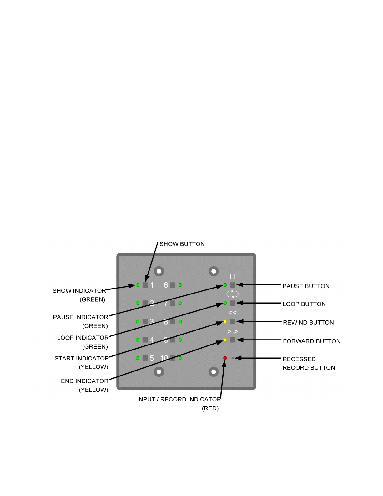
The [REWIND] and [FORWARD] buttons are used to set the start and end points. These buttons are only
active while a show is paused. When paused, the buttons can be used to move the playback pointer
forward or backward through the show. The longer each button is held, the faster the show will be
forwarded or rewound. When the playback pointer is at the top of the recorded show, the START LED will
flash. When the playback pointer reaches the bottom of the recorded show, the END LED will flash. When
the playback pointer is at the START POINT, the START LED will turn on solid. When the playback
pointer is at the end point, the END LED will turn on solid. See below for the meanings of these terms and
for details on editing them.
Start point
The START POINT is the point in the show at which playback will begin when that show is selected. To
set the START POINT, do the following:
1. Start playing the show to be edited.
2. Pause the show near the desired START POINT.
3. While paused, use the [REWIND] or [FORWARD] buttons to move the playback pointer and locate
the desired START POINT.
4. Press and hold the recessed [RECORD] button. A paper clip can be used to push this button.
While holding the [RECORD] button, press the [REWIND] button. After it is pressed, the START
LED will turn on indicating that this point in the show is the start.
Note:
!The START POINT is set to the top of the show when that show is first recorded.
!The START POINT must be set to a point in the show before the END POINT. If you attempt to set the START POINT
to a point after the END POINT , the set START POINT command will be ignored.
!Once recorded, show data is never discarded. If you set a START POINT a few minutes into a recorded show, those
minutes of data still exist. You can start the show, pause it, and rewind into the previously trimmed out area. A new
START POINT can then be set.
End point
The END POINT is the end of the show. To set the END POINT, do the following:
1. Start playing the show to be edited.
2. Pause the show near the desired END POINT.
3. While paused, use the [REWIND] or [FORWARD] button to move the playback pointer and locate
the desired END POINT.
4. Press and hold the recessed [RECORD] button. A paper clip can be used to push this button.
While holding the [RECORD] button, press the [FORWARD] button. After it is pressed, the END
LED will turn on indicating that this point in the show is the END POINT.
Note:
!The END POINT is set to the bottom of the show when that show is first recorded.
!The END POINT must be set to a point in the show after the START POINT. If you attempt to set the END POINT to
a point before the START POINT, the set END POINT command will be ignored.
!Once recorded, show data is never discarded. If you set an END POINT a few minutes before the bottom of a recorded
show, those minutes of data still exist. You can start the show, pause it, and forward into the previously trimmed out
area. A new END POINT can then be set.

Page 11 of 14
EDITING SHOW PARAMETERS (CONTINUED)
Looping
By default, shows are looping. This means that when the show comes to its end, the show will
automatically re-start itself from the START POINT and run in a continuous loop. When looping is disabled,
the show stops at the END POINT and the Rerun Architectural will send the last levels of the show until
another show is selected.
The looping feature can be temporarily enabled or disabled as described in the show playback section.
To permanently change a show’s looping status, do the following:
1. Start playing the show to be edited.
2. Pause the show at any point. The LOOP LED will immediately display the recorded status of the
looping feature for that show. When the LOOP LED is on, looping is enabled.
3. Press and hold the recessed [RECORD] button. A paper clip can be used to push this button.
While holding the [RECORD] button, press the [LOOP] button. After it is pressed, the LOOP LED
will change indicating the shows new looping status.
4. Press the [PAUSE] button to save the new loop status with the show and to resume playing.
Note:
!When a show selection button is pressed, the loop status will be updated from the recorded show data. This will
override any manual looping selections made previously.
Linking
This feature is for advanced users only. Linking is similar to show looping. However, with linking, when
a show reaches its end, instead of looping to re-start itself, a different show is started. You can select
which show is linked. This powerful feature allows the user to create longer and more complex shows.
To link shows, do the following:
1. Start playing the first show.
2. Pause the show at any point.
3. If it is not enabled already, enable looping for the show (Looping section above).
4. Press and hold the recessed [RECORD] button. A paper clip can be used to push this button.
While holding the [RECORD] button, press one of the [SHOW] buttons to choose which show will
play after the current one. The LED for that show will flash and the LED for the current show will
remain on solid.
5. Press the [PAUSE] button to save the new settings and to resume the show. When the show you
just edited finishes playing, the linked show will begin playing. The link and loop status of the next
show will be executed with the new show.
Note:
!To re-link a show to itself, simply edit the link as described above, but select the current show as the show to be linked.
The current show LED will stay on solid and all other show selection LED’s will turn off.
!Turning off the loop feature also disables the link function for the current show.
!When paused, the loop and link status for the current show are displayed.

Page 12 of 14
EDITING SHOW PARAMETERS (CONTINUED)
Cross fading
Each show can have the cross fade function enabled or disabled. When enabled (the default state), the
show will execute a two second fade from the current levels to the levels at the START POINT of the show
when that show is selected. When cross fading is disabled for a show, the levels will jump immediately
from the current levels to the levels at the START POINT of the show.
To enable or disable cross fading, do the following:
1. Start playing the show to be edited.
2. Pause the show at any point.
3. Press and hold the number 10 [SHOW] button. Hold the number 10 [SHOW] button for about
five seconds. While held, the remaining [SHOW LEDS] will indicate the status of other show
and system parameters. The number 3 [SHOW LED] indicates the status of the cross fade
option for that show. While continuing to hold the number 10 [SHOW] button, press the
number 3 [SHOW] button to toggle the state of the option. When the number 3 [SHOW LED] is
lit, the cross fade option is enabled. Set the cross fading option as desired.
4. Release the number 10 [SHOW] button.
5. Press the [PAUSE] button to save the new settings and to resume the show. The next time the
show is selected, it will start using the cross fade option as just recorded.
End of show output
When a show is set to stop running at the END POINT (not looping) the behavior of the Rerun Architectural
can be set up in two different ways. By default, a show stops at its END POINT and the Rerun
Architectural continues to send the last levels of that show until a new show is selected. Each show can
be set up to stop sending DMX512 data entirely at the end of the show. By going off-line, many moving
lights and dimming systems will detect the loss of DMX512 and begin their shut down routines.
To alter the end-of-show behavior, do the following:
1. Start playing the show to be edited.
2. Pause the show at any point.
3. If it is not disabled already, disable looping for the show (Looping section above).
4. Press and hold the number 10 [SHOW] button. Hold the number 10 [SHOW] button for about five
seconds. While held, the remaining [SHOW LEDS] will indicate the status of other show and
system parameters. The number 2 [SHOW LED] indicates the status of the end-of-show output
option for that show. While continuing to hold the number 10 [SHOW] button, press the number
2 [SHOW] button to toggle the state of the option. When the number 2 [SHOW LED] is lit, the
Rerun Architectural will stop DMX512 output at the end of the show. When the number 2 [SHOW
LED] is off, the Rerun Architectural will continue sending DMX512 at the end of the show. Set the
end-of-show transmission option as desired.
5. Release the number 10 [SHOW] button.
6. Press the [PAUSE] button to save the new settings and to resume the show.
Note:
!The end-of-show behavior will only apply if the show has looping disabled.
!If the pile-on feature is enabled, the DMX512 output will remain active if there is an input signal present. In this case,
the output will remain active even if the completed show is set to disable the DMX512 output.

Page 13 of 14
EDITING SHOW PARAMETERS (CONTINUED)
Software record lockout
In addition to the hardware jumper record lockout feature, the Rerun Architectural has a software record
lockout feature. When the software record lockout is enabled, no shows can be recorded and no
parameter data can be modified. The hardware record lockout jumper takes precedence over the software
record lockout. If the hardware record lockout jumper is removed, no data can be altered regardless of
the state of the software record lockout feature.
To alter the software record lockout status, do the following:
1. Start playing any show.
2. Pause the show at any point.
3. Press and hold the number 10 [SHOW] button. Hold the number 10 [SHOW] button for about five
seconds. While held, the remaining [SHOW LEDS] will indicate the status of other show and
system parameters. The number 1 [SHOW LED] indicates the status of the software record lockout
output option. While continuing to hold the number 10 [SHOW] button, press the number 1
[SHOW] button to toggle the state of the option. When the number 1 [SHOW LED] is lit, the Rerun
Architectural will not allow any show or parameter data to be changed. When the number 1
[SHOW LED] is off, the Rerun Architectural will allow changes to be made. Set the software record
lockout option as desired.
4. Release the number 10 [SHOW] button.
5. Press the [PAUSE] button to save the new settings and to resume the show.
Note:
!The software record lockout feature is a global system parameter. Although it can be accessed from any show, there
is only one record lockout state.
!By default, the hardware lockout jumper is installed (recording enabled), and the software record lockout feature is
disabled (recording enabled).
!The hardware record lockout jumper must be installed for the software record lockout to have any effect on the system.
Front panel lockout
The front panel buttons on the Rerun Architectural can be locked to prevent tampering with a running
show. The ability to lock out the front panel is disabled by default.
To enable or disable the ability to lock the front panel, do the following:
1. Start playing any show.
2. Pause the show at any point.
3. Press and hold the number 10 [SHOW] button. Hold the number 10 [SHOW] button for about five
seconds. While held, the remaining [SHOW LEDS] will indicate the status of other show and
system parameters. The number 4 [SHOW LED] indicates the status of the front panel lockout
output option. While continuing to hold the number 10 [SHOW] button, press the number 4
[SHOW] button to toggle the state of the option. When the number 4 [SHOW LED] is lit, the Rerun
Architectural will allow the front panel to be locked. When the number 4 [SHOW LED] is off, the
Rerun Architectural will not allow the front panel to be locked. Set the front panel lockout enable
option as desired.
4. Release the number 10 [SHOW] button.
5. Press the [PAUSE] button to save the new settings and to resume the show.
Note:
!The front panel lockout enable feature is a global system parameter. Although it can be accessed from any show, there
is only one front panel lockout enable state.
!By default, the front panel can not be locked.
!See the Front panel lockout section in the LOCKING THE FRONT PANEL section for operational details.

Page 14 of 14
EDITING SHOW PARAMETERS (CONTINUED)
Grand master
A grand master feature is available as a factory option. This feature allows the user to alter the overall
level output of the current show. The REWIND and FORWARD buttons are used to access this feature
while the show is running. The REWIND button raises the grand master and the FORWARD button lowers
it.
Note:
!The grand master feature can only be enabled at the factory. It can not be enabled in the field.
!The grand master feature is disabled by default.
!When enabled, the grand master feature does not alter the levels of the incoming DMX512 levels.
WARRANTY
Products manufactured by Doug Fleenor Design carry a five year parts and labor warranty against
manufacturing defects. It is the customer's responsibility to return the product to Doug Fleenor Design (at
the customer's expense). Doug Fleenor Design will repair the unit and return it to the customer (at Doug
Fleenor Design's expense). If a trip is necessary to the customer's site to solve a problem, the expenses
of the trip must be paid by the customer.
Note that this warranty is against Manufacturing Defects. It does not include damage due to misuse or
abuse. Most non-warranty repairs are made for a fixed $30.00 fee.
Table of contents