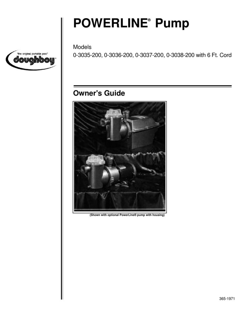
Doughboy POWERLINE XP II User manual

Swimming Pool Pump (Black color model)
With Automatic Timer
3 FT CORD
Models 0-3395-226, 0-3396-226, 0-3397-226, 0-3398-226
25 FT CORD W/GFCI
Models 0-3395-220, 0-3396-220, 0-3397-220, 0-3398-220
6 FT CORD
Models 0-3395-223, 0-3396-223, 0-3397-223, 0-3398-223
Owner's Guide
365-2073
POWERLINE XP II

2
Article 680-31 of the National
Electrical Code (NEC), (Section
68-204 of the Canadian Electrical
Code [CSA]) and local codes or
ordinances. For runs greater than 25
feet, consult your local licensed
electrical contractor.
MODELS ONLY:
0-3395-226, 0-3396-226, 0-3397-226
and 0-3398-226
Your pump is supplied with a 3-foot,
3-wire electrical cord and 3-prong
flanged, twist-lock plug.
The pump electrical cord must be
connected to a single twist lock,
grounding type receptacle that is
located a minimum of 6 feet from the
inside pool wall.
A qualified electrical contractor must
install this receptacle in accordance
with Article 680-6 of the National
Electrical Code (NEC). A Ground
Fault Circuit Interrupter (GFCI) must
be used. An ON/OFF switch must be
installed at the receptacle.
Use a Hubbell No. 2310 Receptacle,
20 AMP 125 Volt A.C. or an
equivalent receptacle that meets
NEMA Configuration L5-20R.
This pump is double insulated and
grounded. Dead metal parts are not
in contact with pool water.
FOR 6FT cord MODELS ONLY:
Your pump is supplied with a 6-foot,
3-wire electrical cord and 3-pronged
plug. The pump is double insulated
and grounded. The pump electrical
cord must be connected to a
grounded, 3-wire, 115 VAC electrical
receptacle. The receptacle must be
protected by a Ground Fault Circuit
Interrupter (GFCI) in accordance
with Article 680-31 of the National
Electrical Code (NEC), (Section 68-
204 of the Canadian Electrical Code
[CSA]) and local codes or
ordinances. For runs greater than 6
feet, consult your local licensed
electrical contractor.
IMPORTANT SAFETY
INSTRUCTIONS
FOR ALL MODELS:
When installing and using this
electrical equipment, basic safety
precautions should always be
followed, including the following:
1. READ AND FOLLOW ALL
INSTRUCTIONS.
2. WARNING — To reduce the risk
of injury, do not permit children to
use this product unless they are
closely supervised at all times.
3. WARNING — Risk of electric
shock. Connect only to a
grounding type receptacle
protected by a Ground Fault
Circuit Interrupter (GFCI).
Contact a qualified electrician if
you cannot verify that the
receptacle is protected by a
GFCI.
(For storable pool pumps) This
product is provided with a
ground-fault circuit interrupter. If
replacement of the plug or cord is
needed, use only identical
replacement parts.
(For all permanently installed
units) Connect only to a branch
circuit protected by a ground-fault
circuit-interrupter (GFCI)
4. Do not bury cord. Locate cord to
minimize abuse from lawn
mowers, hedge trimmers, and
other equipment.
5. WARNING — To reduce the risk
of electric shock, replace
damaged cord immediately.
6. WARNING — To reduce the risk
of electric shock, do not use
extension cord to connect unit to
electric supply; provide a
properly located outlet.
MODELS ONLY:
0-3395-220, 0-3396-220, 0-3397-220
and 0-3398-220
7. CAUTION — This pump is for
use with storable pools only. Do
not use with permanently
installed pools. A storable pool is
constructed so that it may be
readily disassembled for storage
and reassembled to its original
integrity. A permanently installed
pool is constructed in or on the
ground or in a building such that
it cannot be readily disassembled
for storage.
(For storable pools) The unit is
provided with a ground-fault
circuit-interrupter (GFCI). To test
the GFCI, push the test button.
The GFCI should interrupt power.
Push the reset button. Power
should be restored. If the GFCI
fails to operate in this manner,
the GFCI is defective. If the GFCI
interrupts power to the pump
without the test button being
pushed, a ground current is
flowing, indicating the possibility
of an electric shock. Do not use
this pump. Disconnect the pump
and have the problem corrected
by a qualified service
representative before using.
MODELS ONLY:
0-3395-226, 0-3396-226, 0-3397-226
and 0-3398-226
8. CAUTION — This pump is for
use with permanently installed
pools and may also be used with
hot tubs and spas if so marked.
Do not use with storable pools. A
permanently installed pool is
constructed in or on the ground or
in a building such that it cannot
be readily disassembled for
storage. A storable pool is
constructed so that it may be
readily disassembled for storage
and reassembled to its original
integrity.
FOR ALL MODELS:
9. SAVE THESE INSTRUCTIONS.
ELECTRICAL FEATURES
MODELS ONLY:
0-3395-220, 0-3396-220, 0-3397-220
and 0-3398-220
Your pump is supplied with a 25-foot,
3-wire electrical cord and 3-pronged
plug. The pump is double insulated
and grounded. The pump electrical
cord must be connected to a
grounded, 3-wire, 115 VAC electrical
receptacle. The receptacle must be
protected by a Ground Fault Circuit
Interrupter (GFCI) in accordance with

3
air to escape. Tighten lid when
water begins to flow between
strainer pot body and lid. Do not
overtighten.
ABOUT THE TIMER AND
OPERATION
AUTO SETTING:
This pump is equipped with an
automatic timer which has three
modes of operation: “OFF,” “AUTO”
and “CONT.” In the auto mode, there
are five lengths of run time to choose
from: 4, 6, 8, 10, and 12 hours.
To operate the pump in the
automatic mode, select the run
time (in hours). The timer operates
on a 24 hour cycle which starts
when the timer knob is turned from
the "OFF" position to selected run
length time ("start" time).
After plugging in the pump, turn the
timer knob to the desired run time
position. The pump will run for the
amount of hours that was selected,
then shut off automatically. The
pump will automatically start again 24
hours from the time the timer knob
was switched from "OFF" to the
desired "run" time.
Example (the current day and time is
Saturday, 8:00 a.m.):
1. Select 6 hours running time with
the timer knob.
2. Pump will start.
3. Pump will shut off at the end of
six hours (2:00 p.m.).
4. Pump will turn on automatically
the following day (Sunday), 24
hours from the time it was
plugged in (8:00 a.m.).
5. In our example, the pump will
start every day at 8:00 a.m., and
shut off every day at 2:00 p.m.
MANUAL SETTINGS:
To operate the pump with the manual
setting, set the timer knob to “CONT”
position.
Selecting the “CONT” position allows
you to run the pump continuously for
functions such as vacuuming.
Selecting the “OFF” position cuts
power to the motor. Selecting
“OFF” will affect the “start” time
or the cycle you had previously
selected.
TO CHANGE THE LENGTH OF
TIME THE PUMP WILL RUN:
Turn the timer knob to the new hour
selection desired (you do not need to
switch pump off).
Examples:
1. The Timer is on “AUTO” but
the pump is not running: The
newly selected length of time will
take effect the following day at
the regular start time.
2. The Timer is on “AUTO” and
the pump is running: If the new
selected length of time is shorter
than the current length of time
indicated, the pump will shut off
according to the new selection.
3. The Timer is on “AUTO” and
the pump is running: If the new
selected length of time is longer
than the current length of time
indicated, the pump will continue
running and shut off at the new
selected length of time.
TO CHANGE THE TIME THE PUMP
WILL START:
To change the time that the pump will
start in the “AUTO” mode, switch the
timer knob to "OFF". Turn the timer
knob on at the desired start time.
You must wait a minimum of 30
seconds between turning the pump
"OFF" and back on.
NOTE: In the event of a power
failure, the timer will act as though it
has been turned "OFF, and back on
when power is restored. In the
“AUTO” mode, the pump will start
running its cycle when power is
restored. You will have to reset your
“start” time by turning the timer "OFF"
, and turning it back on at your
desired “start” time.
IMPORTANT:
INSTRUCTIONS AND
SAFETY INFORMATION
If you have purchased a filtration
system (consisting of a filter, a pump,
and a pump base), follow the
instructions provided with your filter
instructing you to prepare the filter
and pump foundation using patio
blocks and a level. Failure to use a
pump base will cause the motor to
overheat and will void any warranty.
Install filter and pump a minimum of 6
feet from the pool wall so they may
not be used as steps by children.
PUMP ASSEMBLY
1. Align the rectangle peg on the
base with the mating hole in the
pump housing (see pic below)
and refer to exploded view.Turn
the pump upside-down and place
the pump base into the notches in
the pump. Attach the pump to
the pump base using the four (4)
5/8" hex head screws supplied.
2. Place the O-rings over the
threads of the hose adaptors and
screw them into the intake and
discharge ports on the pump.
Caution: Do not over-tighten.
INITIAL START-UP
1. If you have a Doughboy filtration
system, follow the "Initial Start-
Up" instructions in the filter
owner's guide.
2. If this pump has been purchased
as a replacement (and you are
not referring to the filter
instructions), the pump will have
to be primed after all hose
connections have been made and
pool has been filled to the proper
level. To prime the pump, loosen
the pump strainer pot lid to allow

4
CLEANING STRAINER
BASKET
1. Stop pump. Insert a winterizing
disk or stuff a rag into the return
fitting to close off water flow from
the pool.
2. Remove skimmer basket. Stuff a
rag into the bottom of the
skimmer outlet port.
3. Remove strainer pot lid, lift out
basket, and clean thoroughly.
When replacing the basket, align
notch in basket with rib in strainer
pot. Clean and lubricate O-ring
with a non-petroleum lubricant.
Consult your pool store for proper
lubricant. Replace lid. Remove
winterizing disk and/or rags, and
replace basker and skimmer lid.
Only hand-tighten the lid.
WIRING DIAGRAM
20
21
CIRCUIT
BOARD
POWER CORD INTO
MOTOR ENCLOSURE
Exploded View
Pump
with Automatic Timer
MAINTENANCE
Make sure the pump is discon-
nected from the electrical source
before attempting any maintenance
work.
LUBRICATION:
Periodically lubricate the O-ring under
the strainer cover with a non-
petroleum lubricant recommended for
A.B.S., Noryl and Acrylic plastics.
Consult your pool dealer for lubricant
selections.
If you have questions or require
assistance, contact your pool dealer.

5
PUMP & MOTOR PARTS LIST
ITEM P/N QTY DESCRIPTION MODEL
1 1121-1429 1 Strainer Cover All
2 308-1065 1 Strainer O-Ring All
3 1107-1018 1 Strainer Basket All
4 1121-2008 1 1/4" Pipe Plug w/O-ring All
5 321-1021 6 1/4"-20 Flange Nut All
6 340-2288 1 Strainer Pot All
7 308-1064 1 Pump O-Ring All
8 340-2682 1 Pump Volute All
9 1107-1388 1 Impeller 3/4 & 1 HP Models
1107-1547 1 Impeller 1-1/2 & 2 HP Models
10 1121-1057 1 Seal Set All
11 1107-1659 1 Pump Housing All
12 330-1106 6 1/4"-20 x 2" Flange Bolt All
13 300-1028 1 3/4 HP Motor 0-3395-xxx
300-1028 1 1 HP Motor 0-3396-xxx
300-1102 1 1-1/2 HP Motor 0-3397-xxx
300-1109 1 2 HP Motor 0-3398-xxx
13a 310-1054 1 Baffle Foam (not shown) All
14 1121-1969 1 Motor Enclosure - UL/NEC All
15 1100-1707 1 Power Cord - 6 FT All -223 Models
1100-1115 1 Power Cord - UL/NEC 3 FT All -226 Models
1100-1695 1 Power Cord GFCI 3/4 & 1 HP 0-3395-220, 0-3396-220
1100-1696 1 Power Cord GFCI 1.5 & 2 HP 0-3397-220, 0-3398-220
16 303-1120 1 Strain Relief Bushing - UL/NEC -226 Models
303-1715 1 Strain Relief Bushing - UL/CSA -223 & -220 Models
17 330-1057 4 10-16 x 5/8" Hex Washer Screw All
18 340-2285 1 Pump Base All
19 348-1041 4 Stem Bumpers All
20 1100-1221 1 Jumper Wire-Black 3/4 - 1 HP
1100-1400 1 Jumper Wire-Black 1.5 - 2 HP
21 1100-1223 1 Jumper Wire-White 3/4 - 1 HP
1100-1116 1 Jumper Wire-White 1.5 - 2 HP
22 1100-1690 1 Timer Circuit Board All
23 330-1023 6 #8 x 5/8" Hex Washer Screw All
24 340-2350 1 Timer Knob All
25 308-1042 2 O-Ring, Hose Adaptor All
26 340-2290 2 Hose Adaptor All
27 343-1074 1 Switch hole cover plug All
28 340-2608 1 Strainer cover wrench (not shown) All
ALL MODELS
28 365-2073 1 Owner's Guide
29 — 1 Warranty

6
PROBLEMS:
1. Motor will not start. (See page 7 for
additional trouble shooting information.)
2. Pump will not prime.
3. Motor will stop without being turned off,
then restart later.
4. High pressure gauge reading with low
return flow.
5. Low pressure gauge reading with low
return flow.
6. Leak from front of pump.
REMEDIES:
1. Make sure pump is plugged into a
grounded, 3-wire, 115 V. electrical
receptacle that is not overloaded with
other appliances.
2. Check for improper or loose
connections, open switches or relays,
blown circuit breaker or fuses.
3. The use of an electrical extension cord
may cause a low power source. Have
a qualified electrician install a Ground
Fault Circuit Interrupter (GFCI) for
direct electrical access.
1. Make sure pool is filled to proper level.
Make sure pump, strainer pot and
hoses leading to and from pump are
filled with water. Make sure strainer
cover is secure and cover O-ring is
clean and properly sealed. Keep hose
connections tight to prevent water and/
or air leaks.
2. Clean out strainer basket, skimmer
basket and hoses if necessary.
1. Have a qualified electrician install a
Ground Fault Circuit Interrupter (GFCI)
for direct electrical access, or use a
heavier gauge extension cord.
2. Properly elevate pump 2 to 3 inches
above foundation according to
instructions.
3. Locate bind and remove cause.
4. Replace motor.
1. Backwash Filter.
2. Plug skimmer and return fitting, then
clear debris from return line.
1. Plug skimmer and return fitting, then
disassemble pump and clean impeller.
2. Plug skimmer and return fitting, then
clear debris from suction line.
1. Replace pump O-ring.
2. Replace pump seal set.
3. Replace pump volute.
TROUBLE SHOOTING CHECKLIST FOR PUMP & MOTOR
NOTE: ALWAYS BE SURE PUMP IS DISCONNECTED FROM ELECTRICAL SOURCE
BEFORE ATTEMPTING ANY MAINTENANCE OR REPAIR WORK.
POSSIBLE CAUSE:
1. Pump not plugged in.
2. Faulty electrical outlet.
3. Low voltage.
1. Air in pump.
2. Clogged inlet and/or outlet
connections.
1. A too long or too light extension cord.
2. Blocked air vents on bottom of pump
housing causing motor to overheat.
3. There may be a bind in motor causing
overload.
4. Thermal protector in motor is faulty.
1. Filter is dirty.
2. Plugged or restricted return line.
1. Plugged or restricted impeller.
2. Clogged skimmer basket and/or
plugged suction line leading to pump.
1. Defective pump O-ring.
2. Worn pump seal set.
3. Cracked pump volute.

7
PROBLEMS:
1. If pump does not run.
2. When first plugged in, pump runs in
“CONT” position, but not in “AUTO”
position.
3. Humming sound in “AUTO” and
“CONT” positions, but pump won't run.
4. Pump runs continuously.
REMEDIES:
1. Test electrical outlet with another
working appliance. Check for
improper or loose connections, open
switches or relays, blown circuit
breaker or fuses.
2. Check for improper or loose
connections. Refer to wiring diagram
decal inside pump housing.
3. The use of an electrical extension cord
may cause a low power source. Have
a qualified electrician install a Ground
Fault Circuit Interrupter (GFCI) for
direct electrical access.
4. Replace power cord.
1. Replace timer module.
1. Plug skimmer and return fitting, then
disassemble pump and clean impeller.
2. Replace motor.
1. Move timer knob to “AUTO” or “OFF”
position.
2. Power loss will reset timer. If switch is
in “AUTO,” pump will begin running
when power is restored.
3. Check for improper or loose
connections. Refer to wiring diagram
decal inside pump housing.
4. Replace timer module.
TROUBLE SHOOTING CHECKLIST FOR AUTOMATIC TIMER
NOTE: ALWAYS BE SURE PUMP IS DISCONNECTED FROM ELECTRICAL SOURCE
BEFORE ATTEMPTING ANY MAINTENANCE OR REPAIR WORK.
POSSIBLE CAUSE:
1. Faulty electrical outlet.
2. Faulty internal wiring.
3. Low Voltage.
4. Defective power cord.
1. Defective timer module.
1. Plugged or restricted impeller.
2. Worn or defective motor.
1. Pump is in “CONT” position.
2. Power interruption has occured.
3. Faulty internal wiring.
4. Defective timer module.

8
WARNINGS
1. Always be sure the ground under
your feet and body is dry before
you touch the filter and pump
electrical equipment. Failure to
follow this warning may cause
injury due to severe electrical
shock.
2. Make sure pump is disconnected
from electrical source before
servicing pump and filter
equipment.
LOCAL CODES
Contact your local building
department for applicable codes or
regulations governing the installation
of swimming pool equipment.
CONTRACTED
ELECTRICIANS
Always have a licensed electrician
install electrical components to make
sure electrical integrity is maintained
in accordance with the pump data
label. Improper installation to power
supply may damage the pump motor.
CAUTIONS
1. Do not install pump and filter
system where flooding may
occur. This could damage the
pump motor.
2. Do not install filter and pump on a
deck, or similar surface, above
pool water level. They could fall
into the pool water, causing
severe electrical shock.
3. Do not allow children or adults to
climb, sit or stand on the filter or
pump. They could easily fall and
injure themselves. Install the
filter and pump a minimum of
6 feet from the pool wall so they
may not be used as steps by
children.
Change of Design: Doughboy Recreational expressly reserves the right to change or modify the design and construction of any
product in due course of our manufacturing procedures, without incurring any obligation or liability to furnish or install such changes
or modifications on products previously or subsequently sold.
Doughboy Recreational
315 N. Sebastian St. • West Helena, AR 72390
Visit our website at www.doughboy-pools.com
DB 0912-618 Made in the United States of America Copyright © 2012
This manual suits for next models
12
Table of contents
Other Doughboy Water Pump manuals
Popular Water Pump manuals by other brands

GORMAN-RUPP PUMPS
GORMAN-RUPP PUMPS 82H2-B Installation, operation, and maintenance manual with parts list

Kamoer
Kamoer F1 quick start guide

Nordson
Nordson VDK-MIDI TYPE 6 operating instructions

SKC
SKC AirChek Connect operating instructions

BUSCH
BUSCH Mink MI 1252 BV Installation and operating instructions

T.I.P.
T.I.P. EXTREMA 600/14 CX Translation of original operating instructions