S SERIES TRIPLE SCREW PUMPS 8
SECTION 5
INSTALLATION
PIPING SYSTEM
Since the pump’s basic operating parts are designed to be axed
on screws, extremely close running clearances exist between the
screws and the body; therefore, it is very important to have the
piping (especially the suction-side piping) cleaned thoroughly
before connecting the piping to the pump anges.
After the pump unit has been installed and secured on its
foundation, pipe connections may be installed.
NOTE: Please see pump outline drawing for location of all pipe
connections, ange sizes and other notes pertinent to piping.
Pipes should be as short and direct as possible. Use long radius
elbows to change direction when needed.
Suction piping must be at least the same size of the inlet diameter;
it is acceptable if the suction pipes are one class larger than the
inlet. For example, if the size of the inlet is 150 mm (6 in), the
suction pipes could be 200 mm (8 in). The pipe diameter (length of
pipe should be four [4x] times that of the pipe’s diameter) is used
to connect the suction pips and the inlet. Discharge piping should
be the same size as the diameter of the outlet.
All major piping parts, including suction pipes, discharge pipes,
valves and strainers, should be supported independently and
installed properly to avoid any unnecessary strain on the pump.
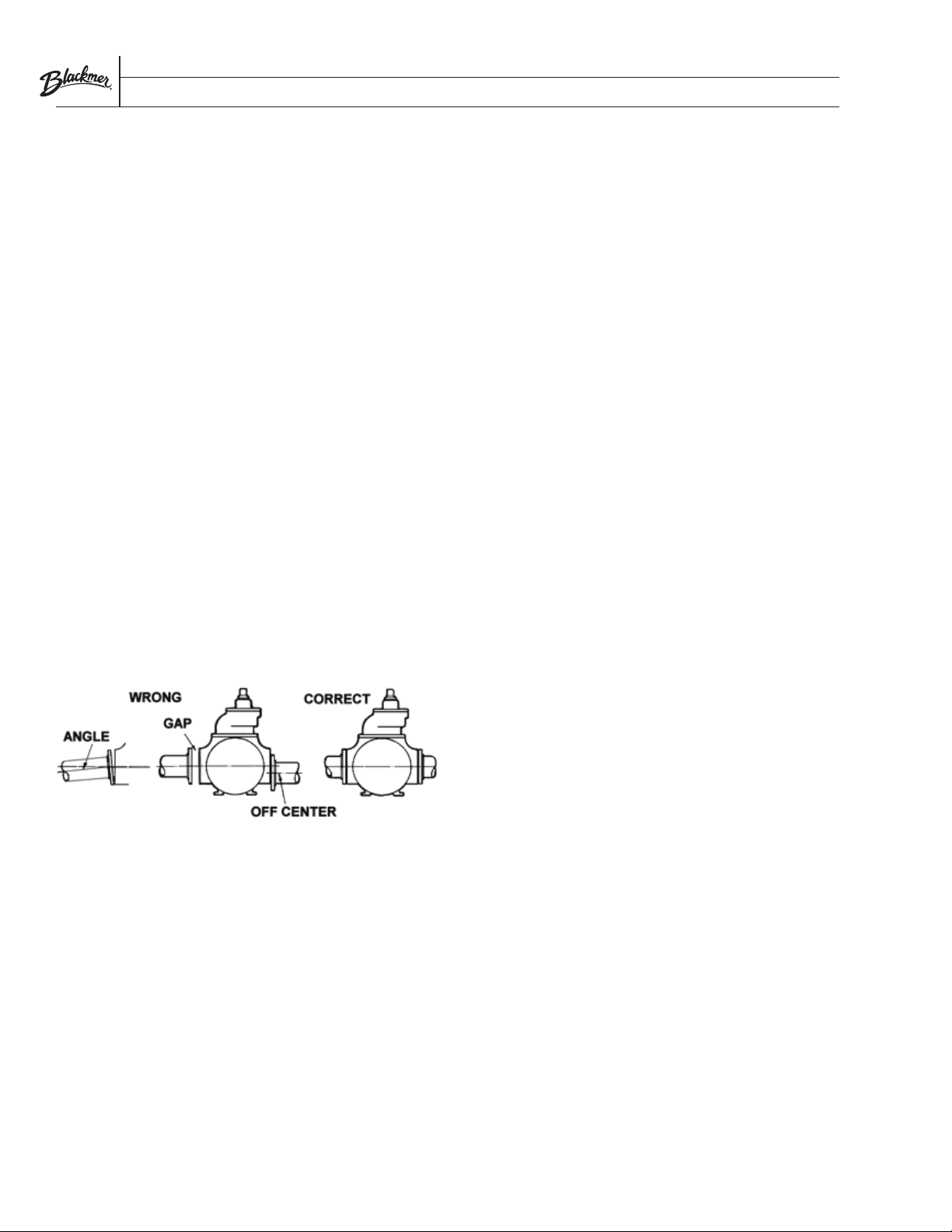
The piping anges must be properly aligned with the pump
anges. To check alignment, insert ange bolts through the pipe
and pump ange. If the bolts are easily moved within the bolt
holes and if the ange faces are parallel with each other, the
piping is properly aligned.
All the valves and lters on the suction pipes and discharge
pipes shall be supported independently and secured to avoid
transmitting the stress to the pump body. The ange of the pipes
shall be straightly facing the anges on the pump. Check the
alignment between the pipes and ports by looking at the through
holes on the pipe anges and port anges. If the bolts can move
freely through the holes and the anges are parallel to each other,
then it is deemed that the pipes are aligned.
If the pump is required to operate with suction lift, the suction piping
system must be properly made in relation to the original design.
NOTE: NPSHa of suction piping must be larger than pump’s NPSHr.
The pump cannot be expected to overcome deciencies in the
suction piping system, such as narrow/thin runs of suction piping,
numerous elbows, valves and excessively high points above pipe
suction, etc. In such cases, cavitation will invariably occur and the
pump may not operate at normal capacity.
Pump and pump accessories should be kept apart by valves to avoid
any force while pressure testing or washing the piping system.
PIPING SYSTEM ACCESSORIES
SUCTION STRAINERS
Blackmer suggests that suction strainers be installed on the
suction side of the pump at least temporarily until the new system
is deemed clean of solid residue. The screen area of the strainer
should be as large as possible. Generally, the strainer screen should
be constructed of 40 meshes, and 10 or 20 meshes for high-viscosity
applications. The net screen area should be approximately ve (5)
to eight (8) times the ow cross-sectional area of the suction pipe.
However, if the viscosity of the media is in excess of 200 mm2/s,
then approximately 10 to 20 times the pipe cross-sectional area
is suggested for the net screen area. The maximum dierential
pressure is 0.1 bar (1.5 psig). Install pressure gauges on either side
of the strainer to indicate when the strainer should be cleaned. The
installed strainer should be easy to maintain and clean.
Generally, strainers can be used on all liquids except for those of
an extremely high viscosity. In these cases, the strainer cannot be
installed; therefore, piping and accessory cleaning is mandatory.
CHECK VALVE
If the discharge piping system is subject to a high static head and if
the uid handled ows back into the pump cavity when stopping
the pump, a check valve should be installed. This valve will prevent
hydraulic shock acting upon the pump, and, most importantly, it
allows for separately starting the pump in a parallel connection
system.
PRESSURE RELIEF VALVE
An external pressure relief valve must be installed between the
pump discharge flange and the gate valve (on the discharge pipe
after the discharge port) to protect the pump and the piping
system. The pressure and flow rating should match the working
pressure and flow of the pump, and media through the valve must
return to the suction source.
NOTICE: The pump internal pressure-limiting valve is designed
to protect the pump from excessive pressure and must not be
used as a system pressure control valve.
GAUGES
Proper gauges must be installed to monitor and control the pump
while in operation. A pressure gauge and a vacuum gauge can be
separately installed on the inlet and outlet piping near the pump.