DPR SCR22 User manual

USER MANUAL
SCR22 / SCR22PL / SCR35 / SCR35PL
this product is certified:
WITH GRAPHTEC CE7000-40
REV. 02


IMPORTANT: Please keep the original packaging in
case you need to return the material. If we receive the
system in non-original packaging, the warranty will be
void.
IMPORTANT: The latest version of the Scorpio Series
software is available on our websites
or ,section “Download”.


I N D E X
2
.....................................................................................page 3
...............................................................................page 3
.................................................................................page 3
......................................................................page 4
.........................................................................page 6
....................................page 7
...................................................................page 8
.................................................................................page 9
...............................................................................page 9
......................................................................page 9
...........................................................page 10
..........................................................page 12
................................................page 13
.................page 13
.............................................................page 15
.................................................................................page 15
...........................................................................................page 16
...................................................................................page 16
.............................................................................page 17
........................page 17
.................................................................page 18
................................................................................page 18
...............................................................................page 19
.....................................................................page 19
....................................page 21
...................................................................................................page 22
........................................................................page 22
.......................page 23
........................................................................page 24
................................................page 24
..................................................page 24
................................................................................page 25
..............................................................................page 27
...................................................................page 27
....................................................................page 28
...........................................................................................page 29
System requirements
How to install outer discs
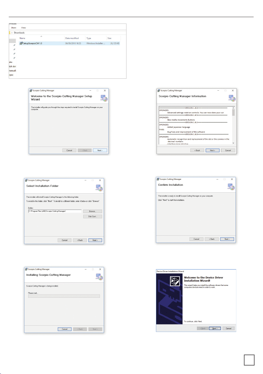
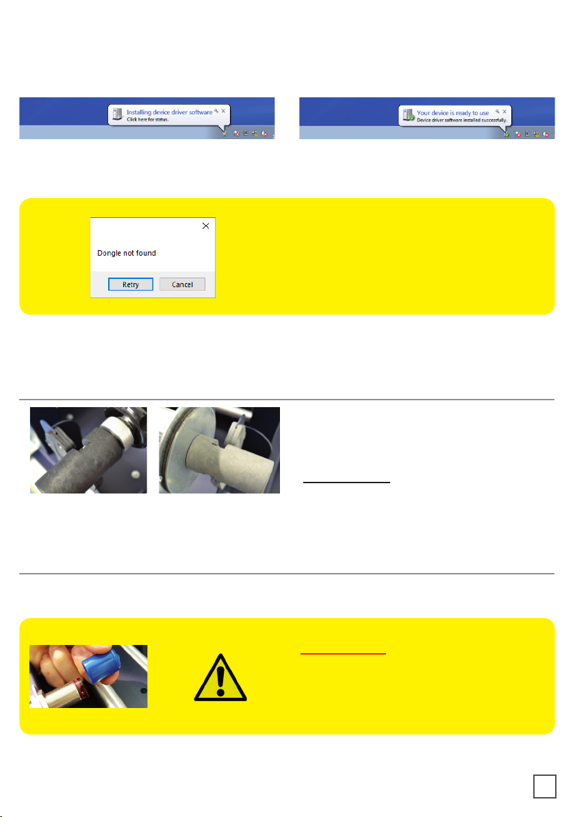
How to install the plotter
How to install the cutting plotter
How to install the core holder
How to load and operate with the lamination module
How to set the lamination sensor
How to adjust the clutch
When to adjust the clutch
Load the media into the plotter
How to run the cut test and start a job
How load the matrix remover & slitter
How to load the matrix remover core holder
How to load the rewinder core holder and set the slitter module
How to add or remove blade holder
Metal guide alignment
Error Messages
Black-mark detection
Black-mark position in the media
How to cut blank labels
How to update software
How to restore plotter settings
How and when to reduce the plotter feeding speed
Media path
Ultrasonic sensor calibration
Lamination / matrix remover&slitter modules speed rotation
How to install pressing roller
Adaptor for the Scorpio SCR35 / SCR35PL
How to used the o-ring on the matrix roller
Graphtech mantenaice
How to replace the knife
How to replace the slitter blade
How to replace the cutting mat
Troubleshooting

The cutting manager works on windows
OS from vista. We do not guarantee its
functionality on windows XP.
Corel Draw (PDF).
panel.
3
Using a screwdriver, install the outer disc on
the Core Holder for printed rolls.
SYSTEM REQUIREMENTS
HOW TO INSTALL OUTER DISC
HOW TO INSTALL THE PLOTTER
A. Pull the plotter from the packaging and place it on the plate, make sure to push the
rubber feet into the holes.
B. Plug the machine and switch on.
A B

1. Click on “SetupScorpioCM...” and follow
the step by step instructions to complete
the installation.
Please DO NOT connect the scorpio
USB to your pc before the installation is
complete
2. Click NEXT
4. Click NEXT 5. Click YES
6. In process
HOW TO INSTALL THE CUTTING PLOTTER
7. Click NEXT
4
3. Click NEXT

9. Click OK
10. Click NEXT (Remove the scorpio USB
from your pc, and turn o the scorpio)
11. Click NEXT
12. Choose the right model name of your
Graphtec (CE7000-40).
Click NEXT
13. Wait until the sign “Update for
the Graphtec CE7000-40 driver was
completed” shows up. You may need to
restart the computer.
Click OK
The installation is completed. A ScorpioCM shortcut is displayed on your desktop
5
8. Click FINISH

Plug in the USB camera and the USB dongle, they will auto-install.
If your computer already has a camera installed, we recommend disabling it. If you
do not, your pc will ignore the camera on the plotter.
CM Software will generate a folder in the Windows start menu.
If the USB dongle is not installed correctly
or is unplugged, the following error will
appear.
The grey handle must match with the
grey holder and the black handle with
the black holder.
IMPORTANT: screws must be face
down.
HOW TO INSTALL THE CORE HOLDER
HOW TO LOAD AND OPERATE THE LAMINATION MODULE
IMPORTANT:
If you don’t use the lamination roll
please cover the sensor with the blue
cap.
Just for SCR22PL and SCR35PL models
6

Load the printed roll and move it against
the roll guide. Tighten the core holder.
Load the lamination roll, move it along
the supply shaft and make sure the
lamination is aligned with the media roll.
IMPORTANT: the lamination roll always
needs to be narrower than the web width.
Example: if the web width is 7” then the lamination roll
needs to be lesser than 7” (let’s say ¼ inch on each end).
At this point you can tighten the core
holder.
When the LEDs on the control board
feeding.
Move the media through the rollers and
press the FORWARD button. The media
will be loaded through the rollers whereas
if you push the BACKWARD button, the
rollers will roll the media backwards.
Load an empty cardboard core onto
the shaft intended for laminate liner
rewinding. Tighten the core holder.
Core Holder No. 1 intended for laminate
use
Core Holder No. 2 intended for laminate
liner use
Core Holder No. 3 intended for printed roll
use
1 2
3
7

!PLEASE LOOK AT THE LAMINATION PATH! (PAGE 21)
Using the two black knobs located at the
top of the roller assemble to adjust the
pressure of the rollers. This will apply
to the media avoiding any possible air
bubbles.
When the green LED is on, the automatic feeding is activated and operated by the
ultrasonic sensor. When both yellow and green LEDs are on, it indicates the system is in
error mode. The cause is due to the media or laminate roll is not detected or it is run out.
If this is not the cause, please reset the sensor.
Turn the screw on the sensor clockwise
or anticlockwise. This operation has to
be done without lamination in place.
If there is no lamination in place, the
LED will light on.
If there is lamination in place, the LED
HOW TO SET THE LAMINATION SENSOR
8

Both core holders are clutched
(unpowered), they are the same and
they work indipendently.
It is possible to adjust the clutch by
screwing or loosing the aluminium
handle.
adjusting. If the tension is too tight the roller system will get damaged or if the tension is
too loose, the media will not be laminated properly.
Pull the laminated media underneath the tension arm, than pass it through the aluminium
rollers, the guide can be adjusted preventing the web from rolling.
Put the lever, located in the rear of the plotter, in the down position.
Pull the media through the plotter and keep the media edge aligned to the alignment
points.
Set both pinch rollers at the media edge.
HOW TO ADJUST THE CLUTCH
WHEN TO ADJUST THE CLUTCH
LOAD THE MEDIA INTO THE PLOTTER
9

While holding down the media in the aligned position, lift the lever back to its up position.
This will lock the media in place.
Press button 2 as requested on plotter’s display.
>> How to run the black-mark mode
User Interface at page 16 might be helpful.
1. Open Scorpio Cutting Manager.
2. Press “OPEN PDF” or “OPEN LAST JOB
3. Look at the camera preview, hold down “BACKWARD MEDIA” or “FORWARD MEDIA”
arrows to move the web until the black-mark goes in the center position of the blue
rectangle area.
4. Measure the distance in (MM) between the top of one black-mark to top of the next
black-mark, key in this value in the “DISTANCE BETWEEN BLACKMARKS” box section.
HOW TO RUN THE CUT TEST AND START A JOB
IMPORTANT:
Working with SCR22 or SCR35 models, please open “ADVANCED
BUTTON”, click on Settings and uncheck Media/Lamination Sensor
option, then save and close the pop up.
6. Press “CUT TEST” to check for cut depth. If the liner has been cut, decrease the cutter
pressure value in the cut force box. If label doesn’t detach, increase the cutter pressure
value in the cut force box.
7. Make sure label is aligned with the cut.
doesn’t match label.
10

+
+
8. Once the cut settings are properly set, select “COPY MODE” ON if you desire a preset
quantity of copies or OFF
9. Set the black-mark size” in “BLACK-MARK MODE” area.
10. Press “START”.
IMPORTANT:
Whenever you lower and rise the lever while you are in black-mark
mode, hold down the forward media arrow button to move again the
plotter’s head down.
>> How to run the blank mode
2. Set the copy mode ON, and set 2 as number of copies.
3. Click “START”.
4. Check the horizontal position and the gap between the cuts.
6. Once the cut is set properly, select copy mode: ON if you desire a preset quantity of
copies, or OFF to cut until the media roll is empty.
7. Working with SCR22 or SCR35 models, please open Advanced button, click on Settings
and uncheck Media/Lamination Sensor option, then save and close the pop up.
8. Click “START”.
IMPORTANT:
Working with SCR22 or SCR35 models, please open “ADVANCED
BUTTON”, click on Settings and uncheck Media/Lamination Sensor
option, then save and close the pop up.
11

After you CUT TEST is successful,
press “START” to cut a few labels until
you think you have enough media to
load onto the matrix remover.
Pull the media through the aluminium
in order to prevent the web from rolling)
then through the clutch system.
Close the loading system and the
media will be automatically loaded into
the clutch path.
The user can adjust the clutch force thanks to the position of the clutch system.
Maximum Cluth (rewinded roll more tight)
Minimum Cluth (rewinded roll less tight)
HOW LOAD THE MATRIX REMOVER & SLITTER
Pull the sides of the black knobs and lift up the clutch system, other black knobs will keep
it open.
Minimum clutch
Maximum clutch
12

1. Load empty cardboard core(s) and tighten the core holder, then place the motorized
core holder in position.
2. Peel back the matrix.
3. Pull the matrix and attach it to the matrix remover core holder.
1. Load empty cardboard core(s) and tighten the core holder, then place the motorized
core holder in position.
(Cardboard core(s) width should equal (or narrower) the width of the nished roll).
2. Pull the media through the aluminium rollers and attach the labels to the core using a
waste label.
WARNING: Before starting a job, always remove the waste
media from the matrix remover core.
Tape the matrix securely onto the cardboard core.
System operating issues may occur if the above
suggestions are not followed.
HOW TO LOAD THE MATRIX REMOVER CORE HOLDER
HOW TO LOAD THE REWINDER CORE HOLDER AND SET THE
SLITTER MODULE
13

Slitter module has 3 positions:
- Upper position (A), the blades are lifted to allow the media loading;
- Middle position (B), align the blades with the edges and the center of the labels, tighten
the thumb screw once the blade is in position;
- Lower position (C), the blade cut the media.
OPEN CLOSE
B
C
A
The black knobs lock the slitter
module in the requested position.
Screw the thumb knobs to move the
blades to the right or to the left.
A
B C
3. Turn ON the Matrix Remover
module to rewind and start to split
the media, than turn OFF.
14

5. Make sure the tension on all rolls is even and attach each label to the core using a
waste label;
6. Feed edges trim waste into the waste basket under the hole.
Remove the iron bar by unscrewing
the black thumb screw.
1
Slide in or out the blade holder.
Relocate the slide iron bar in its
position and rescrew the thumb screw.
2
Metal guides can be adjusted in order to prevent the web from rolling.
HOW TO ADD OR REMOVE A BLADE HOLDER
METAL GUIDE ALIGNMENT
15

If the plotter is not connected correctly to the computer, the following errors will be
displayed at the application launch:
Make sure the plotter is switched on and properly connected.
the button 2 on control panel and wait until the display will show
“READY” as status. Then press retry on the popup window.
Ensure the media is loaded properly. Raise the lever on the
plotter, then press the number 2 on control panel. wait until the
display will show “READY” as the status. Then press retry on the
popup window.
To prevent any issues, it is important that the camera is reading the black-mark properly.
Look at the camera preview, hold down “BACKWARD MEDIA” or “FORWARD MEDIA”
arrows to move the web until the black-mark goes in the center position of the blue
rectangle area.
16
ERROR MESSAGGES
BLACK-MARK DETECTION

The cutting shape must be 100% black (otherwise in case of dashed lines, it must be a
100% magenta normal line) and have a thickness of 1 pt.
The Scorpio Cutting Manager (SCORPIO CM) work with the VECTOR PDF FILE. You
can create this le with Adobe Illustrator or Corel Draw.
minimum distance from
left side of label graphics
4mm
black-mark
can overlap
label on
bottom
Black-mark size: 4x4mm or 2x2mm
4mm is the minimum distance betwen black-mark
and label graphics on bottom side.
Black-mark be the leftmost object.
for round or complex labels
black-mark can partially
overlap the left side of label.
17
BLACK-MARK POSITION INTO THE CUTTING FILE AND PRINTED ARTWORK
black mark having a size of 4x4mm or 2x2mm.
saved instead of hiding or disabling any extra content.
CUTTING FILE SPECIFICATIONS
This manual suits for next models
3
Table of contents
Other DPR Finisher manuals